EP2281968A2 - Procédé et dispositif de soudure ou de collage de joints de construction plats - Google Patents
Procédé et dispositif de soudure ou de collage de joints de construction plats Download PDFInfo
- Publication number
- EP2281968A2 EP2281968A2 EP20100006379 EP10006379A EP2281968A2 EP 2281968 A2 EP2281968 A2 EP 2281968A2 EP 20100006379 EP20100006379 EP 20100006379 EP 10006379 A EP10006379 A EP 10006379A EP 2281968 A2 EP2281968 A2 EP 2281968A2
- Authority
- EP
- European Patent Office
- Prior art keywords
- welded
- heated
- infrared radiator
- waterproofing
- roller
- Prior art date
- Legal status (The legal status is an assumption and is not a legal conclusion. Google has not performed a legal analysis and makes no representation as to the accuracy of the status listed.)
- Granted
Links
Images

Classifications
-
- E—FIXED CONSTRUCTIONS
- E04—BUILDING
- E04D—ROOF COVERINGS; SKY-LIGHTS; GUTTERS; ROOF-WORKING TOOLS
- E04D15/00—Apparatus or tools for roof working
- E04D15/04—Apparatus or tools for roof working for roof coverings comprising slabs, sheets or flexible material
-
- B—PERFORMING OPERATIONS; TRANSPORTING
- B29—WORKING OF PLASTICS; WORKING OF SUBSTANCES IN A PLASTIC STATE IN GENERAL
- B29C—SHAPING OR JOINING OF PLASTICS; SHAPING OF MATERIAL IN A PLASTIC STATE, NOT OTHERWISE PROVIDED FOR; AFTER-TREATMENT OF THE SHAPED PRODUCTS, e.g. REPAIRING
- B29C65/00—Joining or sealing of preformed parts, e.g. welding of plastics materials; Apparatus therefor
- B29C65/02—Joining or sealing of preformed parts, e.g. welding of plastics materials; Apparatus therefor by heating, with or without pressure
- B29C65/14—Joining or sealing of preformed parts, e.g. welding of plastics materials; Apparatus therefor by heating, with or without pressure using wave energy, i.e. electromagnetic radiation, or particle radiation
- B29C65/1403—Joining or sealing of preformed parts, e.g. welding of plastics materials; Apparatus therefor by heating, with or without pressure using wave energy, i.e. electromagnetic radiation, or particle radiation characterised by the type of electromagnetic or particle radiation
- B29C65/1412—Infrared [IR] radiation
-
- B—PERFORMING OPERATIONS; TRANSPORTING
- B29—WORKING OF PLASTICS; WORKING OF SUBSTANCES IN A PLASTIC STATE IN GENERAL
- B29C—SHAPING OR JOINING OF PLASTICS; SHAPING OF MATERIAL IN A PLASTIC STATE, NOT OTHERWISE PROVIDED FOR; AFTER-TREATMENT OF THE SHAPED PRODUCTS, e.g. REPAIRING
- B29C65/00—Joining or sealing of preformed parts, e.g. welding of plastics materials; Apparatus therefor
- B29C65/02—Joining or sealing of preformed parts, e.g. welding of plastics materials; Apparatus therefor by heating, with or without pressure
- B29C65/14—Joining or sealing of preformed parts, e.g. welding of plastics materials; Apparatus therefor by heating, with or without pressure using wave energy, i.e. electromagnetic radiation, or particle radiation
- B29C65/1429—Joining or sealing of preformed parts, e.g. welding of plastics materials; Apparatus therefor by heating, with or without pressure using wave energy, i.e. electromagnetic radiation, or particle radiation characterised by the way of heating the interface
- B29C65/1432—Joining or sealing of preformed parts, e.g. welding of plastics materials; Apparatus therefor by heating, with or without pressure using wave energy, i.e. electromagnetic radiation, or particle radiation characterised by the way of heating the interface direct heating of the surfaces to be joined
-
- B—PERFORMING OPERATIONS; TRANSPORTING
- B29—WORKING OF PLASTICS; WORKING OF SUBSTANCES IN A PLASTIC STATE IN GENERAL
- B29C—SHAPING OR JOINING OF PLASTICS; SHAPING OF MATERIAL IN A PLASTIC STATE, NOT OTHERWISE PROVIDED FOR; AFTER-TREATMENT OF THE SHAPED PRODUCTS, e.g. REPAIRING
- B29C65/00—Joining or sealing of preformed parts, e.g. welding of plastics materials; Apparatus therefor
- B29C65/48—Joining or sealing of preformed parts, e.g. welding of plastics materials; Apparatus therefor using adhesives, i.e. using supplementary joining material; solvent bonding
-
- B—PERFORMING OPERATIONS; TRANSPORTING
- B29—WORKING OF PLASTICS; WORKING OF SUBSTANCES IN A PLASTIC STATE IN GENERAL
- B29C—SHAPING OR JOINING OF PLASTICS; SHAPING OF MATERIAL IN A PLASTIC STATE, NOT OTHERWISE PROVIDED FOR; AFTER-TREATMENT OF THE SHAPED PRODUCTS, e.g. REPAIRING
- B29C66/00—General aspects of processes or apparatus for joining preformed parts
- B29C66/01—General aspects dealing with the joint area or with the area to be joined
- B29C66/02—Preparation of the material, in the area to be joined, prior to joining or welding
- B29C66/024—Thermal pre-treatments
- B29C66/0246—Cutting or perforating, e.g. burning away by using a laser or using hot air
-
- B—PERFORMING OPERATIONS; TRANSPORTING
- B29—WORKING OF PLASTICS; WORKING OF SUBSTANCES IN A PLASTIC STATE IN GENERAL
- B29C—SHAPING OR JOINING OF PLASTICS; SHAPING OF MATERIAL IN A PLASTIC STATE, NOT OTHERWISE PROVIDED FOR; AFTER-TREATMENT OF THE SHAPED PRODUCTS, e.g. REPAIRING
- B29C66/00—General aspects of processes or apparatus for joining preformed parts
- B29C66/01—General aspects dealing with the joint area or with the area to be joined
- B29C66/05—Particular design of joint configurations
- B29C66/10—Particular design of joint configurations particular design of the joint cross-sections
- B29C66/11—Joint cross-sections comprising a single joint-segment, i.e. one of the parts to be joined comprising a single joint-segment in the joint cross-section
- B29C66/112—Single lapped joints
- B29C66/1122—Single lap to lap joints, i.e. overlap joints
-
- B—PERFORMING OPERATIONS; TRANSPORTING
- B29—WORKING OF PLASTICS; WORKING OF SUBSTANCES IN A PLASTIC STATE IN GENERAL
- B29C—SHAPING OR JOINING OF PLASTICS; SHAPING OF MATERIAL IN A PLASTIC STATE, NOT OTHERWISE PROVIDED FOR; AFTER-TREATMENT OF THE SHAPED PRODUCTS, e.g. REPAIRING
- B29C66/00—General aspects of processes or apparatus for joining preformed parts
- B29C66/40—General aspects of joining substantially flat articles, e.g. plates, sheets or web-like materials; Making flat seams in tubular or hollow articles; Joining single elements to substantially flat surfaces
- B29C66/41—Joining substantially flat articles ; Making flat seams in tubular or hollow articles
- B29C66/43—Joining a relatively small portion of the surface of said articles
- B29C66/435—Making large sheets by joining smaller ones or strips together
-
- B—PERFORMING OPERATIONS; TRANSPORTING
- B29—WORKING OF PLASTICS; WORKING OF SUBSTANCES IN A PLASTIC STATE IN GENERAL
- B29C—SHAPING OR JOINING OF PLASTICS; SHAPING OF MATERIAL IN A PLASTIC STATE, NOT OTHERWISE PROVIDED FOR; AFTER-TREATMENT OF THE SHAPED PRODUCTS, e.g. REPAIRING
- B29C66/00—General aspects of processes or apparatus for joining preformed parts
- B29C66/80—General aspects of machine operations or constructions and parts thereof
- B29C66/83—General aspects of machine operations or constructions and parts thereof characterised by the movement of the joining or pressing tools
- B29C66/836—Moving relative to and tangentially to the parts to be joined, e.g. transversely to the displacement of the parts to be joined, e.g. using a X-Y table
- B29C66/8362—Rollers, cylinders or drums moving relative to and tangentially to the parts to be joined
-
- B—PERFORMING OPERATIONS; TRANSPORTING
- B29—WORKING OF PLASTICS; WORKING OF SUBSTANCES IN A PLASTIC STATE IN GENERAL
- B29C—SHAPING OR JOINING OF PLASTICS; SHAPING OF MATERIAL IN A PLASTIC STATE, NOT OTHERWISE PROVIDED FOR; AFTER-TREATMENT OF THE SHAPED PRODUCTS, e.g. REPAIRING
- B29C66/00—General aspects of processes or apparatus for joining preformed parts
- B29C66/80—General aspects of machine operations or constructions and parts thereof
- B29C66/84—Specific machine types or machines suitable for specific applications
- B29C66/865—Independently movable welding apparatus, e.g. on wheels
- B29C66/8652—Independently movable welding apparatus, e.g. on wheels being pushed by hand or being self-propelling
-
- B—PERFORMING OPERATIONS; TRANSPORTING
- B29—WORKING OF PLASTICS; WORKING OF SUBSTANCES IN A PLASTIC STATE IN GENERAL
- B29C—SHAPING OR JOINING OF PLASTICS; SHAPING OF MATERIAL IN A PLASTIC STATE, NOT OTHERWISE PROVIDED FOR; AFTER-TREATMENT OF THE SHAPED PRODUCTS, e.g. REPAIRING
- B29C66/00—General aspects of processes or apparatus for joining preformed parts
- B29C66/90—Measuring or controlling the joining process
- B29C66/91—Measuring or controlling the joining process by measuring or controlling the temperature, the heat or the thermal flux
- B29C66/912—Measuring or controlling the joining process by measuring or controlling the temperature, the heat or the thermal flux by measuring the temperature, the heat or the thermal flux
- B29C66/9121—Measuring or controlling the joining process by measuring or controlling the temperature, the heat or the thermal flux by measuring the temperature, the heat or the thermal flux by measuring the temperature
- B29C66/91221—Measuring or controlling the joining process by measuring or controlling the temperature, the heat or the thermal flux by measuring the temperature, the heat or the thermal flux by measuring the temperature of the parts to be joined
-
- B—PERFORMING OPERATIONS; TRANSPORTING
- B29—WORKING OF PLASTICS; WORKING OF SUBSTANCES IN A PLASTIC STATE IN GENERAL
- B29C—SHAPING OR JOINING OF PLASTICS; SHAPING OF MATERIAL IN A PLASTIC STATE, NOT OTHERWISE PROVIDED FOR; AFTER-TREATMENT OF THE SHAPED PRODUCTS, e.g. REPAIRING
- B29C66/00—General aspects of processes or apparatus for joining preformed parts
- B29C66/90—Measuring or controlling the joining process
- B29C66/91—Measuring or controlling the joining process by measuring or controlling the temperature, the heat or the thermal flux
- B29C66/914—Measuring or controlling the joining process by measuring or controlling the temperature, the heat or the thermal flux by controlling or regulating the temperature, the heat or the thermal flux
- B29C66/9141—Measuring or controlling the joining process by measuring or controlling the temperature, the heat or the thermal flux by controlling or regulating the temperature, the heat or the thermal flux by controlling or regulating the temperature
- B29C66/91411—Measuring or controlling the joining process by measuring or controlling the temperature, the heat or the thermal flux by controlling or regulating the temperature, the heat or the thermal flux by controlling or regulating the temperature of the parts to be joined, e.g. the joining process taking the temperature of the parts to be joined into account
-
- B—PERFORMING OPERATIONS; TRANSPORTING
- B29—WORKING OF PLASTICS; WORKING OF SUBSTANCES IN A PLASTIC STATE IN GENERAL
- B29C—SHAPING OR JOINING OF PLASTICS; SHAPING OF MATERIAL IN A PLASTIC STATE, NOT OTHERWISE PROVIDED FOR; AFTER-TREATMENT OF THE SHAPED PRODUCTS, e.g. REPAIRING
- B29C66/00—General aspects of processes or apparatus for joining preformed parts
- B29C66/90—Measuring or controlling the joining process
- B29C66/91—Measuring or controlling the joining process by measuring or controlling the temperature, the heat or the thermal flux
- B29C66/914—Measuring or controlling the joining process by measuring or controlling the temperature, the heat or the thermal flux by controlling or regulating the temperature, the heat or the thermal flux
- B29C66/9141—Measuring or controlling the joining process by measuring or controlling the temperature, the heat or the thermal flux by controlling or regulating the temperature, the heat or the thermal flux by controlling or regulating the temperature
- B29C66/91431—Measuring or controlling the joining process by measuring or controlling the temperature, the heat or the thermal flux by controlling or regulating the temperature, the heat or the thermal flux by controlling or regulating the temperature the temperature being kept constant over time
-
- B—PERFORMING OPERATIONS; TRANSPORTING
- B29—WORKING OF PLASTICS; WORKING OF SUBSTANCES IN A PLASTIC STATE IN GENERAL
- B29C—SHAPING OR JOINING OF PLASTICS; SHAPING OF MATERIAL IN A PLASTIC STATE, NOT OTHERWISE PROVIDED FOR; AFTER-TREATMENT OF THE SHAPED PRODUCTS, e.g. REPAIRING
- B29C66/00—General aspects of processes or apparatus for joining preformed parts
- B29C66/90—Measuring or controlling the joining process
- B29C66/91—Measuring or controlling the joining process by measuring or controlling the temperature, the heat or the thermal flux
- B29C66/914—Measuring or controlling the joining process by measuring or controlling the temperature, the heat or the thermal flux by controlling or regulating the temperature, the heat or the thermal flux
- B29C66/9161—Measuring or controlling the joining process by measuring or controlling the temperature, the heat or the thermal flux by controlling or regulating the temperature, the heat or the thermal flux by controlling or regulating the heat or the thermal flux, i.e. the heat flux
- B29C66/91651—Measuring or controlling the joining process by measuring or controlling the temperature, the heat or the thermal flux by controlling or regulating the temperature, the heat or the thermal flux by controlling or regulating the heat or the thermal flux, i.e. the heat flux by controlling or regulating the heat generated by Joule heating or induction heating
- B29C66/91655—Measuring or controlling the joining process by measuring or controlling the temperature, the heat or the thermal flux by controlling or regulating the temperature, the heat or the thermal flux by controlling or regulating the heat or the thermal flux, i.e. the heat flux by controlling or regulating the heat generated by Joule heating or induction heating by controlling or regulating the current intensity
-
- B—PERFORMING OPERATIONS; TRANSPORTING
- B29—WORKING OF PLASTICS; WORKING OF SUBSTANCES IN A PLASTIC STATE IN GENERAL
- B29C—SHAPING OR JOINING OF PLASTICS; SHAPING OF MATERIAL IN A PLASTIC STATE, NOT OTHERWISE PROVIDED FOR; AFTER-TREATMENT OF THE SHAPED PRODUCTS, e.g. REPAIRING
- B29C66/00—General aspects of processes or apparatus for joining preformed parts
- B29C66/90—Measuring or controlling the joining process
- B29C66/93—Measuring or controlling the joining process by measuring or controlling the speed
- B29C66/934—Measuring or controlling the joining process by measuring or controlling the speed by controlling or regulating the speed
-
- E—FIXED CONSTRUCTIONS
- E04—BUILDING
- E04D—ROOF COVERINGS; SKY-LIGHTS; GUTTERS; ROOF-WORKING TOOLS
- E04D15/00—Apparatus or tools for roof working
- E04D15/06—Apparatus or tools for roof working for handling roofing or sealing material in roll form
-
- B—PERFORMING OPERATIONS; TRANSPORTING
- B29—WORKING OF PLASTICS; WORKING OF SUBSTANCES IN A PLASTIC STATE IN GENERAL
- B29C—SHAPING OR JOINING OF PLASTICS; SHAPING OF MATERIAL IN A PLASTIC STATE, NOT OTHERWISE PROVIDED FOR; AFTER-TREATMENT OF THE SHAPED PRODUCTS, e.g. REPAIRING
- B29C65/00—Joining or sealing of preformed parts, e.g. welding of plastics materials; Apparatus therefor
- B29C65/02—Joining or sealing of preformed parts, e.g. welding of plastics materials; Apparatus therefor by heating, with or without pressure
- B29C65/14—Joining or sealing of preformed parts, e.g. welding of plastics materials; Apparatus therefor by heating, with or without pressure using wave energy, i.e. electromagnetic radiation, or particle radiation
- B29C65/1403—Joining or sealing of preformed parts, e.g. welding of plastics materials; Apparatus therefor by heating, with or without pressure using wave energy, i.e. electromagnetic radiation, or particle radiation characterised by the type of electromagnetic or particle radiation
- B29C65/1412—Infrared [IR] radiation
- B29C65/1416—Near-infrared radiation [NIR]
-
- B—PERFORMING OPERATIONS; TRANSPORTING
- B29—WORKING OF PLASTICS; WORKING OF SUBSTANCES IN A PLASTIC STATE IN GENERAL
- B29C—SHAPING OR JOINING OF PLASTICS; SHAPING OF MATERIAL IN A PLASTIC STATE, NOT OTHERWISE PROVIDED FOR; AFTER-TREATMENT OF THE SHAPED PRODUCTS, e.g. REPAIRING
- B29C65/00—Joining or sealing of preformed parts, e.g. welding of plastics materials; Apparatus therefor
- B29C65/48—Joining or sealing of preformed parts, e.g. welding of plastics materials; Apparatus therefor using adhesives, i.e. using supplementary joining material; solvent bonding
- B29C65/4805—Joining or sealing of preformed parts, e.g. welding of plastics materials; Apparatus therefor using adhesives, i.e. using supplementary joining material; solvent bonding characterised by the type of adhesives
- B29C65/481—Non-reactive adhesives, e.g. physically hardening adhesives
- B29C65/4825—Pressure sensitive adhesives
-
- B—PERFORMING OPERATIONS; TRANSPORTING
- B29—WORKING OF PLASTICS; WORKING OF SUBSTANCES IN A PLASTIC STATE IN GENERAL
- B29C—SHAPING OR JOINING OF PLASTICS; SHAPING OF MATERIAL IN A PLASTIC STATE, NOT OTHERWISE PROVIDED FOR; AFTER-TREATMENT OF THE SHAPED PRODUCTS, e.g. REPAIRING
- B29C66/00—General aspects of processes or apparatus for joining preformed parts
- B29C66/003—Protecting areas of the parts to be joined from overheating
-
- B—PERFORMING OPERATIONS; TRANSPORTING
- B29—WORKING OF PLASTICS; WORKING OF SUBSTANCES IN A PLASTIC STATE IN GENERAL
- B29C—SHAPING OR JOINING OF PLASTICS; SHAPING OF MATERIAL IN A PLASTIC STATE, NOT OTHERWISE PROVIDED FOR; AFTER-TREATMENT OF THE SHAPED PRODUCTS, e.g. REPAIRING
- B29C66/00—General aspects of processes or apparatus for joining preformed parts
- B29C66/80—General aspects of machine operations or constructions and parts thereof
- B29C66/87—Auxiliary operations or devices
- B29C66/874—Safety measures or devices
- B29C66/8742—Safety measures or devices for operators
-
- B—PERFORMING OPERATIONS; TRANSPORTING
- B29—WORKING OF PLASTICS; WORKING OF SUBSTANCES IN A PLASTIC STATE IN GENERAL
- B29C—SHAPING OR JOINING OF PLASTICS; SHAPING OF MATERIAL IN A PLASTIC STATE, NOT OTHERWISE PROVIDED FOR; AFTER-TREATMENT OF THE SHAPED PRODUCTS, e.g. REPAIRING
- B29C66/00—General aspects of processes or apparatus for joining preformed parts
- B29C66/90—Measuring or controlling the joining process
- B29C66/91—Measuring or controlling the joining process by measuring or controlling the temperature, the heat or the thermal flux
- B29C66/912—Measuring or controlling the joining process by measuring or controlling the temperature, the heat or the thermal flux by measuring the temperature, the heat or the thermal flux
- B29C66/9121—Measuring or controlling the joining process by measuring or controlling the temperature, the heat or the thermal flux by measuring the temperature, the heat or the thermal flux by measuring the temperature
- B29C66/91211—Measuring or controlling the joining process by measuring or controlling the temperature, the heat or the thermal flux by measuring the temperature, the heat or the thermal flux by measuring the temperature with special temperature measurement means or methods
- B29C66/91216—Measuring or controlling the joining process by measuring or controlling the temperature, the heat or the thermal flux by measuring the temperature, the heat or the thermal flux by measuring the temperature with special temperature measurement means or methods enabling contactless temperature measurements, e.g. using a pyrometer
-
- B—PERFORMING OPERATIONS; TRANSPORTING
- B29—WORKING OF PLASTICS; WORKING OF SUBSTANCES IN A PLASTIC STATE IN GENERAL
- B29C—SHAPING OR JOINING OF PLASTICS; SHAPING OF MATERIAL IN A PLASTIC STATE, NOT OTHERWISE PROVIDED FOR; AFTER-TREATMENT OF THE SHAPED PRODUCTS, e.g. REPAIRING
- B29C66/00—General aspects of processes or apparatus for joining preformed parts
- B29C66/90—Measuring or controlling the joining process
- B29C66/91—Measuring or controlling the joining process by measuring or controlling the temperature, the heat or the thermal flux
- B29C66/914—Measuring or controlling the joining process by measuring or controlling the temperature, the heat or the thermal flux by controlling or regulating the temperature, the heat or the thermal flux
- B29C66/9161—Measuring or controlling the joining process by measuring or controlling the temperature, the heat or the thermal flux by controlling or regulating the temperature, the heat or the thermal flux by controlling or regulating the heat or the thermal flux, i.e. the heat flux
- B29C66/91641—Measuring or controlling the joining process by measuring or controlling the temperature, the heat or the thermal flux by controlling or regulating the temperature, the heat or the thermal flux by controlling or regulating the heat or the thermal flux, i.e. the heat flux the heat or the thermal flux being non-constant over time
-
- B—PERFORMING OPERATIONS; TRANSPORTING
- B29—WORKING OF PLASTICS; WORKING OF SUBSTANCES IN A PLASTIC STATE IN GENERAL
- B29C—SHAPING OR JOINING OF PLASTICS; SHAPING OF MATERIAL IN A PLASTIC STATE, NOT OTHERWISE PROVIDED FOR; AFTER-TREATMENT OF THE SHAPED PRODUCTS, e.g. REPAIRING
- B29C66/00—General aspects of processes or apparatus for joining preformed parts
- B29C66/90—Measuring or controlling the joining process
- B29C66/96—Measuring or controlling the joining process characterised by the method for implementing the controlling of the joining process
- B29C66/961—Measuring or controlling the joining process characterised by the method for implementing the controlling of the joining process involving a feedback loop mechanism, e.g. comparison with a desired value
-
- B—PERFORMING OPERATIONS; TRANSPORTING
- B29—WORKING OF PLASTICS; WORKING OF SUBSTANCES IN A PLASTIC STATE IN GENERAL
- B29L—INDEXING SCHEME ASSOCIATED WITH SUBCLASS B29C, RELATING TO PARTICULAR ARTICLES
- B29L2031/00—Other particular articles
- B29L2031/10—Building elements, e.g. bricks, blocks, tiles, panels, posts, beams
- B29L2031/108—Roofs
Definitions
- the invention relates to a method for welding sheet-like structural waterproofing according to the preamble of claim 1 and for bonding sheet-like structural waterproofing according to the preamble of claim 7. Furthermore, the invention relates to a corresponding device according to the preamble of claim 10.
- Flat structural waterproofing is mainly used for roofs, floors, walls and bridges.
- rolled-up sealing sheets are usually used.
- adjacent sealing sheets are glued or welded to form a large-area seal.
- overlay sheets are glued or welded to underlay sheets.
- the structural waterproofing welded at least one of the surfaces to be welded construction waterproofing, especially the waterproofing membranes, softened or melted by heating. By subsequent compression of the surfaces to be welded, the welding takes place.
- bituminous structural waterproofing of preferably bituminous sealing membranes it is customary to heat and soften the surfaces to be welded with a burner having an open flame, preferably a gas burner.
- the open flame leads to an increased risk of fire.
- the flame also has an uncontrolled temperature development As a result, the surfaces to be welded are very difficult to heat evenly and no homogeneous welded joint is formed. Finally, the open flame may cause the bitumen to burn, creating dangerous fumes that endanger welding personnel and cause environmental damage.
- Plastic sealing strips are usually welded with hot air. This also leads to an uncontrolled temperature development, which does not allow a uniform heating of the surfaces to be welded and thus leads to inhomogeneous welds.
- the warming of the surfaces to be welded plastic sealing sheets with hot air has a strong smoke result, which endangers the persons entrusted with the welding and environmental pollution.
- the bonding of structural waterproofing is carried out by on the relevant side of the structural waterproofing, in particular waterproofing membrane, applied adhesive.
- These are preferably cold self-adhesive (KSK).
- KSK cold self-adhesive
- the adhesive can be arranged over the full surface as a continuous layer or even only partially, for example in strips or a grid of dots or the like, on the side of the respective sealing strip to be bonded.
- the gluing of the waterproofing membrane takes place only by compressing the sealing sheets to be bonded together.
- the adhesive which is active without heating, in particular cold self-adhesive must be covered by a protective film, which is usually a silicone film or a siliconized plastic film. Before the sealing strip is glued, the protective foil must be removed.
- the protective film is expensive, especially if it is a silicone film or a siliconized plastic film.
- the protective film peeled off from the adhesive side of the respective waterproofing membrane must be disposed of.
- the invention is an object of the invention to provide a method and an apparatus, which surface waterproofing reliable and even without risk to persons and are environmentally friendly welded or protective films to be bonded flat structural waterproofing are easily removable.
- a method for achieving this object comprises the measures of claim 1.
- the fact that the welding is done with infrared rays, can be an exact Realize temperature control.
- the surfaces to be welded are evenly heated and both the plastic of plastic seals and the bitumen of bituminous waterproofing even softenable or melted. This results in high quality, especially full-surface and homogeneous, welds.
- bituminous seals can be welded without an open flame by the invention.
- the surfaces to be welded can be welded without affecting people and without polluting emissions.
- a preferred embodiment of the method provides that shortwave infrared rays are used for welding. This ensures a particularly effective, uniform heating of the surfaces to be welded. Above all, emitters producing short-wave infrared rays can be positioned relatively densely and thus exactly in front of the surfaces to be heated and melted, as a result of which the short-wave infrared rays can be directed in a targeted manner onto the surfaces to be welded.
- the at least one of the surfaces to be welded is continuously heated or softened or melted.
- both surfaces to be welded are heated and softened or melted.
- the continuous heating of at least one of the surfaces to be welded results in that the surfaces to be welded are placed evenly during installation in an optimal state for welding and thus a homogeneous weld, in particular a continuous weld, arises.
- the waterproofing is a waterproofing sheet rolled up on a roll
- it is provided according to a development of the method to continuously heat the surface to be welded at least the sealing sheet located on a roll during the rolling of the roll and to heat or melt ,
- the at least one surface to be welded can be heated during unrolling of the sealing strip, without requiring an additional operation.
- the at least one surface to be welded is heated by at least one infrared radiator, in particular a short-wave infrared radiator, wherein this at least one infrared radiator when rolling the Sealing membrane is guided along preferably with a constant distance in front of the roller.
- at least the surface to be welded of the roll of unrolled sealing sheet can be heated during the rolling of the sealing strip immediately prior to welding.
- the heating and welding of the waterproofing membrane is done so quasi in one operation when rolling the waterproofing membrane from the roll.
- the method it is provided to monitor the maximum setpoint temperature, to which the surfaces to be welded are heated, preferably continuously during the heating. This ensures that the surfaces to be welded are heated to the intended target temperature, but this is not exceeded. Rather, the target temperature or a setpoint temperature range is always complied with, which is favored by the use of infrared heaters which can be controlled simply and accurately in the heating power.
- a further preferred embodiment of the method provides, during the heating of the surfaces to be welded, to determine the surface temperature of at least one of the surfaces to be heated in particular continuously. This can be done, for example, with a radiation pyrometer. By comparing the measured, instantaneous temperature of the surface of at least one of the surfaces to be welded with the maximum setpoint temperature, a reliable temperature control can take place. This ensures that the surfaces to be welded are only heated as much as necessary. A leading to burns heating is thus reliably avoided.
- Another method for solving the above-mentioned problem comprises the measures of claim 7. Accordingly, it is provided to thermally remove the adhesive, in particular cold adhesive, for rolling up the web-like building waterproofing covering protective film by infrared rays. As a result, the protective film does not need to be removed from the adhesive areas or the adhesive layer before disposal of the building waterproofing and disposed of. Due to the infrared rays, the protective film is melted, in particular melted away, thereby releasing the adhesive surfaces. What remains is only a small remnant of the fused plastic of the protective film, which can be easily disposed of.
- the inventive method can be used as a protective film, an inexpensive thin plastic film of a simple plastic that does not need to be siliconized.
- a protective film for example, it may be a polyethylene or polypropylene film having a thickness of less than 20 microns, preferably 5 microns to 10 microns act.
- Such a thin film can be melted up or away with little energy and thus removed from the adhesive thermally.
- Another advantage of the method according to the invention is that is warmed or heated by the taking place by infrared rays melting the protective film of the adhesive, in particular cold self-adhesive. This improves the effectiveness of the adhesive. Above all, the method according to the invention makes it possible to bond building waterproofing in particular with cold self-adhesive at lower temperatures than has hitherto been the case.
- a further preferred embodiment of the method relates to a structural seal in the form of a rolled-up on a roll waterproofing membrane.
- the protective film of the rolled-up waterproofing membrane is thermally removed by the at least one infrared radiator during unrolling of the waterproofing membrane.
- the waterproofing membrane is unrolled continuously during laying, whereby the protective film is successively removed thermally by the at least one infrared radiator during unrolling of the waterproofing membrane. This happens according to the inventive method quasi simultaneously with the rolling when laying the waterproofing membrane, and that immediately prior to bonding the same.
- the protective film is removed from the at least one infrared radiator by melting.
- the infrared radiator is in particular a short-wave infrared radiator.
- the very thin Protective plastic film can be easily melted off by at least one infrared emitter.
- the thin protective film contracts, thereby releasing the adhesive layer or adhesive areas.
- the protective film contracts by melting by means of the at least one short-wave infrared radiator to the extent that apart from a small, compact plastic particles practically nothing remains of it.
- a heating device which has at least one infrared radiator.
- the welded surfaces can be heated in a targeted manner, especially evenly over their entire width, in the case of structural waterproofing to be welded.
- the heat energy of infrared radiators is precisely adjustable, especially in the short-wave range, so that the surfaces to be welded can be heated by the at least one infrared radiator a precise temperature, this temperature is evenly over the entire surface to be welded achieved. This results in an optimal heating of the surfaces to be welded together, creating ideal conditions for a uniform welding of the surfaces to be joined by structural waterproofing, especially waterproofing membranes created.
- the at least one infrared radiator is used to thermally remove the protective film from the adhesive areas or the adhesive layer by melting. This eliminates the need to manually peel off the protective film from the adhesive and dispose of the peeled protective film.
- the adhesive is heated, thereby activating it and resulting in better bonding, in particular at lower temperatures.
- the at least one infrared radiator for removing the protective film does not need to generate as much heat energy as is the case with infrared radiators for welding structural waterproofing.
- the device has a unwinding device for unrolling at least one rolled up on a roll sealing strip, wherein the at least one infrared radiator is associated with this unwinding device.
- a unwinding device for unrolling at least one rolled up on a roll sealing strip, wherein the at least one infrared radiator is associated with this unwinding device.
- the unwinding device is provided to couple the unwinding device with the roll of the sealing strip, with a rolling axis formed by the longitudinal central axis of the roll thereof.
- the coupling of the roller with the unwinding device thus allows a simple unrolling of the sealing strip from the roll.
- the spacer ensures that the at least one infrared radiator on the unwinding device always has approximately the same distance from the roller and thus to the surface to be welded or the protective film of the rolled-up sealing strip to be fused, even if the diameter of the roller is steadily reduced during unwinding of the sealing strip. It may be the same or an additional spacer provided to keep the distance of the at least one infrared radiator to the surface to be heated constant. This is especially true when the same infrared rays heat or melt the surfaces to be welded or the protective films of both to be connected waterproofing membranes.
- a further preferred embodiment of the device provides that the unwinding device is designed as a roll-off carriage, which can be moved along on a base, with which the sealing strip to be unrolled can be moved.
- the Abrollwagen allows a continuous unrolling of the waterproofing membrane, which is continuously softened or melted away by attaching the at least one infrared radiator on Abrollwagen the surface to be welded or the protective film of the unrolling Abdichtbahn and the at least one infrared radiator with always the same distance to the base, whereupon the unrolling Is applied waterproofing membrane, is guided. If the at least one infrared radiator also heats or melts away the second surface or protective foil, the rolling carriage also ensures an always constant distance of the at least one infrared radiator to this second surface.
- the Abrollwagen is preferably designed so that it is hand-held. Incidentally, the Abrollwagen is designed so that it can be pushed by the operator or is self-propelled by a drive.
- the at least one infrared radiator seen in the unwinding direction of the waterproofing sheet to be unrolled at the front of the unrolling cart.
- the at least one infrared radiator can thereby directly heat up the respective surface to be welded or the respective protective film of at least the waterproofing membrane to be unrolled on the underside.
- the unwinding carriage has at least one temperature measuring device, preferably a radiation pyrometer, which determines the surface temperature of at least one of the surfaces to be welded.
- the surface temperature of at least one surface to be heated when unrolling the sealing strip can preferably be measured continuously.
- the heating power of the at least one infrared radiator and / or the unwinding speed of the unrolling waterproofing membrane or the speed at which the Abrollwagen from the drive is selected, in particular regulated, that one or both surfaces to be welded on the intended, optimal temperature to be heated.
- a controlled and uniform heating of the surfaces to be welded is brought about and also reliably prevents excessive heating.
- the at least one infrared radiator thermally removed by melting the protective film of at least one of the two sealing sheets to be joined.
- the figures show the invention in connection with a roof seal.
- the invention is, however, not limited thereto. It is suitable for any structural waterproofing, for example, for bridge waterproofing, floor or wall seals and connections.
- roof seal is formed in two layers.
- a backing layer 10 is on an insulation, not shown, and thereupon an overlay layer 11 applied.
- Both the backing layer 10 and the top layer 11 are formed of adjacent roof sealing sheets, namely underlay sheets 12 and overlay sheets 13.
- the underlay webs 12 and the overlay webs 13 can be arranged in different directions one above the other.
- the overlay webs 13 are arranged above the underlaid webs 12 such that the longitudinal edges 14 of the underlaid webs 12 and the longitudinal edges 15 of the overlay webs 13 intersect at an angle which is for example about 45 °.
- Both the underlay webs 12 and the overlay webs 13 are laid with a small lateral overlap and welded together in the region of the overlaps by lap seams 16 and 17, respectively.
- the overlay webs 13 are welded on the underlay webs 12 over the entire surface, so that a full-surface weld joint of the top layer 11 with the backing layer 10 is formed.
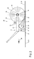
- the Fig. 2 schematically shows a device for welding the underlays 12 and the overlay webs 13 by means of an infrared radiator 18 for heating both surfaces to be welded.
- an overlay web 13 is welded over its entire area to the previously laid underlay webs 12 of the underlay layer 10, and at the same time the overlapping seam 17 is made for joining adjacent overlay webs 13.
- the overlay web 13 to be welded is unwound from a roll 18.
- the roller 18 is rotated about its longitudinal central axis 19.
- the longitudinal central axis 19 of the roller 18 simultaneously forms an unwinding axis.
- the device has a take-off device designed as a take-off carriage 20 in the exemplary embodiment shown.
- the Abrollwagen 20 has a frame 21 with free rotatable wheels 22 on which the Abrollwagen 20 hand-operated and hand-driven along a substrate along, in particular slidably, is.
- the Abrollwagen 20 may also have a drive. Then the Abrollwagen 20 is self-propelled, where he only needs to be guided by hand.
- the Abrollwagen 20 with the wheels 22 in the longitudinal direction of the base layer 10 to be laid on the overlay web 13 is movable.
- the Abrollwagen 20 has at opposite ends of the frame 21 each have an arm 23. At the free end of each arm 23, a transverse mandrel 24 is arranged. The mandrels 24 engage from opposite sides in a hollow axis 25 of each roller 18 of the overlay web 13 a.
- the hollow axle 25, which may optionally be formed by a tube on which the overlay web 13 is wound, lies on the longitudinal central axis 19 of the roller 18, which thus forms an axis of rotation of the roll axis, around which the roller 18 on the also on the longitudinal central axis 19 lying thorns 24 is freely rotatable.
- the roller 18 can be unwound from the roller 18 by moving the unrolling carriage 20 along the laying direction 28 extending in the longitudinal direction of the overlay web 13.
- the Abrollwagen 20 shown here preferably has a plurality of attached to the frame 21 spacers 26. These are based on the outside of the roller 18, preferably with a freely rotatable wheel or a roller.
- the spacers 26 may serve to shorten the optionally telescopically formed arms 23, if the outer diameter thereof is reduced by further unrolling of the overlay web 13 from the roller 18. In this way, the roller 18 is always when the diameter changes, always on the spacers 26 at.
- At Abrollwagen 20 also at least one elongated infrared radiator 27 is arranged. This may be a single over the entire width of the roller 18 with the overlay web 13 extending infrared radiator 27 act. But it is also conceivable to provide a plurality of on a common transverse to the laying direction 28 axis successive, ie arranged in series, shorter infrared radiator 27. In addition, a plurality of infrared radiators 27 may be arranged in parallel, that is to say one above the other and / or one behind the other, where a plurality of infrared radiators 27 may then also be arranged next to each other.
- a plurality of infrared radiators 27 are arranged both in series and in parallel to a grid of multiple infrared radiators 27. At least the outer infrared radiator 27 then have a width corresponding to the width of the overlap seam 16 or 17, so that with the same device not only a full-surface bonding of the overlay sheet 13 the underlay 12 can take place, but also a welding of adjacent underlay webs 12 or overlay webs 13 in the region of the respective overlapping seam 16 and 17, to which then only an outer infrared radiator 27 is operated.
- the infrared radiator 27 has a reflector 29 whose cross-section is formed so that the reflector 29 focuses or focuses infrared rays and directs them to both surfaces to be welded, namely in the illustrated embodiment, the top of the backing layer 10 and réellesch healthenden on this underside of the overlay web 13th
- the reflector 29 is approximately semi-cylindrical in the illustrated embodiment.
- the inner surface of the reflector 29 is formed so as to favor the reflection of the infrared rays.
- the inside of the reflector 28 is provided with a gold or silver-colored coating.
- an elongated heating coil 30 of the infrared radiator 27 is arranged, which extends continuously over the entire length of the infrared radiator 27. It is also conceivable that in the vicinity of the center of the reflector 29 a plurality of parallel and closely spaced heating coils 30 are located.
- the heating coils 30 are electrically operated by annealing in the manner of resistance heating from the current flowing through the heating coils 30 and thereby generate infrared rays, which are directed by the reflector 29 on the surfaces to be welded.
- On Abrollwagen 20 can still at least one in the Fig. 2 not shown temperature sensor be arranged, the surface temperature of at least one of the heated by the infrared radiator 27 to be welded surfaces, namely the welding surfaces 31 and 32 in the Fig. 2 , determined.
- This may be, for example, a radiation pyrometer.
- the Abrollwagen 20 only a very short or narrow infrared radiator 27, which extends only over the region of the relatively narrow overlap seam 16 or 17.
- the Abrollwagen 20 have two short infrared radiator 27 at the opposite ends thereof, whereby overlapping seams 16 and 17 at any ends of the roller 18 of the overlay sheet 13 or other sealing sheet can be produced.
- a small device for the preparation of connections a small device is conceivable, which is not designed as Abrollwagen 20. It is a hand-held device with only at least one relatively short infrared radiator. A frame 21 with spikes 24 for holding the unwinding role 18 is missing in this handset.
- the hand-held device need not have a frame 21 for unwinding a roll 18, because usually only narrow sealing strips are used to form connections.
- This handset also has no wheels 22, because it is quite light because of the very short infrared radiator and it is therefore easy to guide by hand.
- the full-surface bonding of a top layer 11 from side by side with overlap of the longitudinal edges 15 unrolled overlay webs 13 is shown with a backing layer 10 of adjacent backing sheets 12.
- the upper side of the underlay layer 10 is welded over its entire area to the underside of the overlay layers 13 forming the overlay layer 11.
- the surfaces to be welded namely the welding surfaces 31 of the backing sheet 12 and the welding surfaces 32 of the overlay sheet 13, according to the invention by at least one infrared radiator 27 over the entire surface, namely continuously over the entire width of the overlay sheet 13, heated and thereby softened or melted and then the melted welding surfaces 31 and 32 welded together.
- welding surfaces 31 and 32 The heating of the welding surfaces 31 and 32 by the at least one infrared radiator 27 and the joining of the welded in this way welding surfaces 31 and 32 is carried out continuously during the unwinding of the roller 18 rolled on the top sheet 13 on the backing sheet 12 formed from the backing layer 10th
- the at least one electrically operated infrared radiator 27 generates short-wave infrared rays, which are focused by the reflector 29 and focused on the welding surfaces 31 and 32, and shortly before depositing the underside of the unrolling top layer 13 on top of the backing layer 10.
- the top layer web 13 In the full-surface Bonding of the top layer 11 with the backing layer 10 is the top layer web 13 over the entire width of the at least one of the Whole width of the overlay web 13 extending, elongated heating coil 30 generated infrared rays heated and thereby softened or melted.
- the at least one infrared radiator 27 is precisely aligned so that it selectively heats the welding surfaces 31 and 32 by infrared rays.
- the roller 18 is unwound with the locomotion of the Abrollwagens 20 in the laying direction 28 and thereby laid the overlay sheet 13 on the backing layer 10.
- the welding surfaces 31 and 32 of the top layer web 13 of the underlay layer 10 which are heated and softened by the infrared rays, come into contact with each other over their entire area, whereby uninterrupted, full-surface and homogeneous welding of the top layer web 13 to the underlay layer 10 takes place.
- the spacers 26 and Abrollwagen 20 ensure that the distance of the roller 18 from at least one infrared radiator 27 always remains the same. However, because the diameter of the roller 18 is reduced during the rolling of the overlay web 13, in a preferred embodiment of the method, the distance can be kept the same by the mandrels 24 supporting arms 23 of the Abrollwagens 20 are always shortened so far that the roller 18 at the spacers 26 abuts.
- the Abrollwagen 20 with the attached roller 18 of the overlay sheet 13 is moved by hand in the laying direction 28. For this purpose, the Abrollwagen 20 along with the wheels 22 on the backing layer 10 along.
- the Abrollwagen 20 may also have guides that serve to unroll the overlay web 13 always parallel to the already laid overlay webs 13, so that the width of the overlap seam 17 between overlapping next to each other laid overlay webs 13 always has the same width.
- the adjacent overlay webs 13 are also welded. This welding takes place at the same time during full-surface welding of the overlay webs 13 with the backing layer 10th
- the temperature sensor measures the surface temperature of at least one of the welding surfaces 31 and 32. This can be done for example by a radiation pyrometer. The measured surface temperature is either manually provided by the operator of the uncoiler 20 or automatically by an electronic control with the one to be welded Target temperature compared. Depending on whether the setpoint temperature is exceeded or not reached, either an adjustment of the heating power of the at least one infrared radiator 27 and / or a change in speed, whereby the Abrollwagen 20 is further moved with the roller 18 of the overlay webs 13 in laying direction 28.
- the maintenance of the setpoint temperature for welding the overlay web 13 with the backing layer 10 is kept constant by a controller or controller, it makes sense to provide the roll-off carriage 20 with a drive, so that the controller controls the speed of the self-propelled roll-off carriage 20 can.
- the welding surfaces for forming the overlapping seams 16 and 17 between adjacent underlay webs 12 and overlay webs 13 for welding the two-ply underlay web 12 or top coat web 13 in the region of the respective overlap seam 16 and 17 are heated and thereby melted with infrared rays.
- the Abrollwagen 20 but only needs to have a narrow infrared radiator, which extends only across the width of the overlap seam 16 or 17.
- connections preferably building or roof connections
- connections takes place entirely manually.
- the welding surfaces of the sealing strips to be joined are also heated by infrared rays of at least one infrared radiator and thereby softened or melted before welding.
- the method according to the invention is not only suitable for welding overlay webs 13 to underlay webs 12.
- the method can also be used, for example, in structural waterproofing, in particular bridge waterproofing, to lay sealing webs on a suitably prepared weldable substrate and to weld them at least in the area of overlapping seams.
- the invention is suitable for heating the surfaces to be welded by sealing webs of different materials, both bituminous sealing webs and plastic sealing webs.
- the invention also relates to the bonding, in particular cold bonding, of structural waterproofing such as preferably rollable waterproofing membranes.
- structural waterproofing such as preferably rollable waterproofing membranes.
- overlay webs 13 and underlays 12 after in the Fig. 1 be shown kind connected by particular cold gluing.
- both the tops of the underlays 12 and the undersides of the overlay webs 13 may be provided with adhesive, in particular cold end adhesive.
- both the upper sides of the underlay webs 12 and the undersides of the overlay webs 13 can be provided with a full-surface adhesive layer, in particular cold self-adhesive layer.
- tops of the underlays 12 and / or the undersides of the Oberlagsbahnen 13 no full-surface adhesive layers, in particular cold self-adhesive layers have, but are only partially provided with adhesive.
- the tops of the underlay webs 12 and / or the undersides of the overlay webs 13 can only be provided in regions, for example by strips or dots of arbitrary surfaces with adhesive, in particular cold self-adhesive. The dimensions of the strips or patterns can be arbitrary.
- both the upper sides of the underlays 12 and the undersides of the overlay webs 13 are provided over the entire surface with a cold self-adhesive layer.
- the overlay webs 13 and the underlays 12 are then glued together cold on both surfaces facing each other.
- the cold self-adhesive layers are covered over the whole area by protective films, not shown in the figures.
- the protective films are plastic films, preferably polyethylene or polypropylene films.
- the protective films have only a relatively small thickness of less than 20 microns, in particular 5 microns to 10 microns.
- the thickness of the protective films is preferably only 7 ⁇ m to 8 ⁇ m.
- the non-siliconized protective films according to the invention are preferably continuously thermally removed by at least one infrared radiator prior to the gluing together of the overlay webs 13 with the underlays 12.
- the protective films are heated by the infrared heater so far that they melt away, thereby exposing the cold self-adhesive layers at least for the most part. Since the infrared radiators only have to melt away the very thin protective films, they can have a lower heating power than the infrared radiator 27 for welding the overlay webs 13 with the Underlays 12.
- infrared radiators for melting the protective films are preferably also short-wave infrared radiators into consideration.
- the heat generated by the infrared radiators to melt away the protective film also leads to heating of at least external portions of the cold self-adhesive layers under the overlay webs 13 and on the underlays 12. This leads to activation of the cold self-adhesive layers and a resulting more effective cold bonding of the overlay webs 13 on the underlays 12th This is especially true for low temperatures.
- the overlay webs 13 can be glued to the underlays 12 at lower temperatures with cold self-adhesive than is possible with conventional cold bonding of overlay webs 13 with underlays 12.
- the removal of the protective films by at least one infrared radiator from the adhesive surfaces of the cold self-adhesive layers for example, in the Fig. 2 shown device.
- This has one or more infrared emitters 27, which are arranged on the frame 21 of the Abrollwagens 20.
- the Abrollwagen 20 takes on a role of the overlay web 13. This is unrolled with the hand-held and pushed or self-propelled Abrollwagen 20 on the already laid underlay web 12, and preferably as it is in the Fig. 1 is shown and described in connection with this figure.
- the protective films are heated by the infrared radiator 27.
- a heating cone of the infrared radiator 27 is directed to a resulting during rolling of the overlay sheet 13 on the backing sheet 12 gap between the two.
- the infrared radiator 27 simultaneously heats both protective films on the underside of the overlay web 13 and the top of the backing sheet 12.
- the protective films are heated by the infrared radiator 27 so much that they are melted. In this case, the protective films are thermally removed from the cold self-adhesive surfaces to be joined on the upper side of the underlayment web 12 and the underside of the overlay web 13.
- the at least one infrared radiator 27 has a heating energy sufficient to melt the protective films from the backing sheet 12 and the overlay sheet 13 up and away, wherein inevitably the cold self-adhesive layers are warmed or heated at least on the outside.
- the sides of the backing sheet 12 and the overlay sheet 13 to be bonded are only partially provided with cold self-adhesive, namely having cold self-adhesive strips or cold self-adhesive dots.
- the protective films can then run continuously over the entire available surfaces of the backing sheet 12 and the overlay sheet 13, but also only in the areas of the cold self-adhesive. If protective foils are only present in these areas of cold-adhesive adhesives, these are also melted away by the infrared radiators 27 and the exposed areas of the upper side of the underlaid webs 12 and the underside of the overlay webs 13 are warmed by the at least one infrared radiator 27 outside the zone-wise protective foils.
- the invention is also suitable for the case that only one of the roofing membranes to be joined is wholly or partially provided with cold self-adhesive.
- a protective film which is covered by a protective film.
- this protective film from the at least one infrared radiator 27 needs to be removed thermally.
- the at least one infrared radiator 27 melts away not only the protective film on the underside of the overlay sheet 13, but also the top of the backing sheet 12 is warmed without a protective film and cold self-adhesive.
- the method described above for laying in particular cold self-adhesive waterproofing membranes, especially overlay webs 13 and underlays 12, is also suitable for the production of building and roof connections.
- a small device in particular a hand-held device used.
- This handset preferably has only a single, small infrared emitter.
- the protective films are also thermally removed from the underside of the overlay webs 13 and / or the top of the underlay webs 12. This is done by melting or melting away the protective film as a result of the thermal energy exerted by the infrared radiator on the same.
- the infrared radiator of the handset can serve to heat the cold self-adhesive at least on the outside and thereby activate, whereby the bonding is improved, especially at lower temperatures.
Landscapes
- Engineering & Computer Science (AREA)
- Mechanical Engineering (AREA)
- Physics & Mathematics (AREA)
- Thermal Sciences (AREA)
- Electromagnetism (AREA)
- Architecture (AREA)
- Civil Engineering (AREA)
- Structural Engineering (AREA)
- Health & Medical Sciences (AREA)
- Toxicology (AREA)
- Lining Or Joining Of Plastics Or The Like (AREA)
Applications Claiming Priority (2)
| Application Number | Priority Date | Filing Date | Title |
|---|---|---|---|
| DE102009031856 | 2009-07-03 | ||
| DE102010019688A DE102010019688A1 (de) | 2009-07-03 | 2010-05-07 | Verfahren und Vorrichtung zum Verschweißen oder Verkleben flächiger Bauwerksabdichtungen |
Publications (3)
| Publication Number | Publication Date |
|---|---|
| EP2281968A2 true EP2281968A2 (fr) | 2011-02-09 |
| EP2281968A3 EP2281968A3 (fr) | 2013-06-12 |
| EP2281968B1 EP2281968B1 (fr) | 2016-11-02 |
Family
ID=43299232
Family Applications (1)
| Application Number | Title | Priority Date | Filing Date |
|---|---|---|---|
| EP10006379.1A Not-in-force EP2281968B1 (fr) | 2009-07-03 | 2010-06-19 | Procédé de soudure ou de collage de joints de construction plats |
Country Status (3)
| Country | Link |
|---|---|
| US (1) | US20110000611A1 (fr) |
| EP (1) | EP2281968B1 (fr) |
| DE (1) | DE102010019688A1 (fr) |
Cited By (1)
| Publication number | Priority date | Publication date | Assignee | Title |
|---|---|---|---|---|
| EP3406819A1 (fr) * | 2017-05-23 | 2018-11-28 | Taieb Marzouki | Procédé et appareil de raccordement thermique de feuilles et de bandes d'étanchéité thermiques |
Families Citing this family (4)
| Publication number | Priority date | Publication date | Assignee | Title |
|---|---|---|---|---|
| US9376818B1 (en) * | 2013-02-21 | 2016-06-28 | Matthew M Kelly | Apparatus for applying a sheet of fabric across a surface of a roof deck during coating and method of using the same |
| CN110158875A (zh) * | 2019-06-21 | 2019-08-23 | 平顶山环宇星防水科技有限公司 | 防水卷材自动喷胶、铺设一体机 |
| CN112627445B (zh) * | 2021-01-29 | 2022-04-15 | 中冶建工集团有限公司 | 一种用于支撑防水卷材的轴杆 |
| FI131392B1 (fi) * | 2021-12-10 | 2025-03-24 | Vf Yhtioet Oy | Laite rakennusmateriaalin kiinnittämiseksi alustaan |
Family Cites Families (5)
| Publication number | Priority date | Publication date | Assignee | Title |
|---|---|---|---|---|
| DE6941382U (de) * | 1969-10-23 | 1970-02-12 | Infrastrab Bau Propan Kolb Kg | Vorrichtung zum verlegen von bitumenschweissbahnen od. dgl. |
| DE3717608A1 (de) * | 1987-05-25 | 1988-12-15 | Spiess Kunststoff Recycling | Verfahren zum herstellen von schalen, platten etc. aus stark verunreinigten kunststoff-recycling-materialien |
| US4806194A (en) * | 1988-03-07 | 1989-02-21 | Wald Richard D | Roofing paper applicator |
| JP4254647B2 (ja) * | 2004-07-30 | 2009-04-15 | アオイテクノサービス株式会社 | 防水シートの現場貼り付け機械 |
| US8262833B2 (en) * | 2007-07-12 | 2012-09-11 | Building Materials Investment Corporation | Use of infrared technology to install and/or repair construction membranes |
-
2010
- 2010-05-07 DE DE102010019688A patent/DE102010019688A1/de not_active Withdrawn
- 2010-06-19 EP EP10006379.1A patent/EP2281968B1/fr not_active Not-in-force
- 2010-07-01 US US12/828,678 patent/US20110000611A1/en not_active Abandoned
Non-Patent Citations (1)
| Title |
|---|
| None |
Cited By (1)
| Publication number | Priority date | Publication date | Assignee | Title |
|---|---|---|---|---|
| EP3406819A1 (fr) * | 2017-05-23 | 2018-11-28 | Taieb Marzouki | Procédé et appareil de raccordement thermique de feuilles et de bandes d'étanchéité thermiques |
Also Published As
| Publication number | Publication date |
|---|---|
| EP2281968B1 (fr) | 2016-11-02 |
| US20110000611A1 (en) | 2011-01-06 |
| DE102010019688A1 (de) | 2011-01-05 |
| EP2281968A3 (fr) | 2013-06-12 |
Similar Documents
| Publication | Publication Date | Title |
|---|---|---|
| EP2281968B1 (fr) | Procédé de soudure ou de collage de joints de construction plats | |
| EP1063083A2 (fr) | Couverture de toit bitumineuse | |
| EP3269534B1 (fr) | Procede de liaison par soudage ou collage de couches de materiau se chevauchant au moins partiellement et automate de liaison destine a executer le procede | |
| WO2013160170A1 (fr) | Procédé et dispositif pour assembler une première bande de film et une seconde bande de film | |
| EP3015598B1 (fr) | Utilisation d'une membrane de sous-toiture dans des toits inclines ayant des surfaces de toit adjacentes | |
| DE69004262T2 (de) | Bituminöses beschichtungsmaterial und verfahren zur herstellung einer bituminösen beschichtung auf einem substrat. | |
| EP1464471B1 (fr) | Procédé et dispositif pour le soudage par recouvrement de matériaux plastiques plats | |
| EP1963750A1 (fr) | Matelas de chauffage réversible | |
| EP3406819A1 (fr) | Procédé et appareil de raccordement thermique de feuilles et de bandes d'étanchéité thermiques | |
| EP0313735B1 (fr) | Procédé de fabrication d'une bande de bitume imperméable à plusieurs couches | |
| WO2023006518A1 (fr) | Dispositif de soudage au coin chauffant destiné à la liaison plane de bandes d'étanchéité à un support et/ou un subjectile | |
| DE4416452A1 (de) | Vorrichtung zum vollflächigen Verschweißen einer Folie | |
| DE202015004236U1 (de) | Bituminöse Dachabdichtungsbahn | |
| EP1066549A1 (fr) | Procede et vehicule permettant de relier des feutres surfaces poses avec chevauchement des bords | |
| DE4447022C2 (de) | Thermoaktive Selbstklebebahn | |
| EP4534275A1 (fr) | Dispositif de pose d'une bande de matériau et procédé de pose d'une bande de matériau | |
| DE19803045A1 (de) | Anordnung sowie Verfahren zur Befestigung von Abdeck- und/oder Abdichtungsbahnen | |
| WO2001042576A1 (fr) | Procede, dispositif et adhesif thermofusible pour l'etancheification de joints ou de surfaces de batiments | |
| DE10008689A1 (de) | Verfahren zum Verlegen bituminöser Dichtungsbahnen und dafür geeignete Dichtungsbahnen und daraus hergestellte Dachabdichtung | |
| DE3611133C2 (fr) | ||
| DE3615869A1 (de) | Verfahren und vorrichtung zum anschmelzen von bitumenbahnen mit waermedaemm-material | |
| CH694088A5 (de) | Verfahren und Vorrichtung zum vollflächigen Aufschweissen einer Thermoplastbahn auf eine Unterlage. | |
| EP1514975B1 (fr) | Bandes d'étanchéité ou bandes isolantes en bitume | |
| DE102009022918A1 (de) | Schweißvorrichtung und Schweißverfahren | |
| CH661474A5 (de) | Verfahren und vorrichtung zum verbinden der raender von kunststoffbahnen. |
Legal Events
| Date | Code | Title | Description |
|---|---|---|---|
| PUAI | Public reference made under article 153(3) epc to a published international application that has entered the european phase |
Free format text: ORIGINAL CODE: 0009012 |
|
| AK | Designated contracting states |
Kind code of ref document: A2 Designated state(s): AL AT BE BG CH CY CZ DE DK EE ES FI FR GB GR HR HU IE IS IT LI LT LU LV MC MK MT NL NO PL PT RO SE SI SK SM TR |
|
| AX | Request for extension of the european patent |
Extension state: BA ME RS |
|
| RAP3 | Party data changed (applicant data changed or rights of an application transferred) |
Owner name: MARZOUKI, TAIEB |
|
| RIN1 | Information on inventor provided before grant (corrected) |
Inventor name: MARZOUKI, TAIEB |
|
| PUAL | Search report despatched |
Free format text: ORIGINAL CODE: 0009013 |
|
| AK | Designated contracting states |
Kind code of ref document: A3 Designated state(s): AL AT BE BG CH CY CZ DE DK EE ES FI FR GB GR HR HU IE IS IT LI LT LU LV MC MK MT NL NO PL PT RO SE SI SK SM TR |
|
| AX | Request for extension of the european patent |
Extension state: BA ME RS |
|
| RIC1 | Information provided on ipc code assigned before grant |
Ipc: E04D 15/04 20060101AFI20130508BHEP |
|
| 17P | Request for examination filed |
Effective date: 20131122 |
|
| RBV | Designated contracting states (corrected) |
Designated state(s): AL AT BE BG CH CY CZ DE DK EE ES FI FR GB GR HR HU IE IS IT LI LT LU LV MC MK MT NL NO PL PT RO SE SI SK SM TR |
|
| 17Q | First examination report despatched |
Effective date: 20140530 |
|
| RIC1 | Information provided on ipc code assigned before grant |
Ipc: B29C 65/48 20060101ALI20150413BHEP Ipc: B29C 65/00 20060101ALI20150413BHEP Ipc: E04D 15/04 20060101AFI20150413BHEP Ipc: E04D 15/06 20060101ALI20150413BHEP Ipc: B29L 31/10 20060101ALI20150413BHEP Ipc: B29C 65/14 20060101ALI20150413BHEP |
|
| GRAP | Despatch of communication of intention to grant a patent |
Free format text: ORIGINAL CODE: EPIDOSNIGR1 |
|
| INTG | Intention to grant announced |
Effective date: 20160519 |
|
| GRAS | Grant fee paid |
Free format text: ORIGINAL CODE: EPIDOSNIGR3 |
|
| GRAA | (expected) grant |
Free format text: ORIGINAL CODE: 0009210 |
|
| AK | Designated contracting states |
Kind code of ref document: B1 Designated state(s): AL AT BE BG CH CY CZ DE DK EE ES FI FR GB GR HR HU IE IS IT LI LT LU LV MC MK MT NL NO PL PT RO SE SI SK SM TR |
|
| REG | Reference to a national code |
Ref country code: GB Ref legal event code: FG4D Free format text: NOT ENGLISH |
|
| REG | Reference to a national code |
Ref country code: AT Ref legal event code: REF Ref document number: 842019 Country of ref document: AT Kind code of ref document: T Effective date: 20161115 Ref country code: CH Ref legal event code: EP |
|
| REG | Reference to a national code |
Ref country code: IE Ref legal event code: FG4D Free format text: LANGUAGE OF EP DOCUMENT: GERMAN |
|
| REG | Reference to a national code |
Ref country code: DE Ref legal event code: R096 Ref document number: 502010012639 Country of ref document: DE |
|
| REG | Reference to a national code |
Ref country code: NL Ref legal event code: FP |
|
| PG25 | Lapsed in a contracting state [announced via postgrant information from national office to epo] |
Ref country code: LV Free format text: LAPSE BECAUSE OF FAILURE TO SUBMIT A TRANSLATION OF THE DESCRIPTION OR TO PAY THE FEE WITHIN THE PRESCRIBED TIME-LIMIT Effective date: 20161102 |
|
| REG | Reference to a national code |
Ref country code: LT Ref legal event code: MG4D |
|
| PG25 | Lapsed in a contracting state [announced via postgrant information from national office to epo] |
Ref country code: GR Free format text: LAPSE BECAUSE OF FAILURE TO SUBMIT A TRANSLATION OF THE DESCRIPTION OR TO PAY THE FEE WITHIN THE PRESCRIBED TIME-LIMIT Effective date: 20170203 Ref country code: NO Free format text: LAPSE BECAUSE OF FAILURE TO SUBMIT A TRANSLATION OF THE DESCRIPTION OR TO PAY THE FEE WITHIN THE PRESCRIBED TIME-LIMIT Effective date: 20170202 Ref country code: SE Free format text: LAPSE BECAUSE OF FAILURE TO SUBMIT A TRANSLATION OF THE DESCRIPTION OR TO PAY THE FEE WITHIN THE PRESCRIBED TIME-LIMIT Effective date: 20161102 Ref country code: LT Free format text: LAPSE BECAUSE OF FAILURE TO SUBMIT A TRANSLATION OF THE DESCRIPTION OR TO PAY THE FEE WITHIN THE PRESCRIBED TIME-LIMIT Effective date: 20161102 |
|
| REG | Reference to a national code |
Ref country code: FR Ref legal event code: PLFP Year of fee payment: 8 |
|
| PG25 | Lapsed in a contracting state [announced via postgrant information from national office to epo] |
Ref country code: ES Free format text: LAPSE BECAUSE OF FAILURE TO SUBMIT A TRANSLATION OF THE DESCRIPTION OR TO PAY THE FEE WITHIN THE PRESCRIBED TIME-LIMIT Effective date: 20161102 Ref country code: PT Free format text: LAPSE BECAUSE OF FAILURE TO SUBMIT A TRANSLATION OF THE DESCRIPTION OR TO PAY THE FEE WITHIN THE PRESCRIBED TIME-LIMIT Effective date: 20170302 Ref country code: HR Free format text: LAPSE BECAUSE OF FAILURE TO SUBMIT A TRANSLATION OF THE DESCRIPTION OR TO PAY THE FEE WITHIN THE PRESCRIBED TIME-LIMIT Effective date: 20161102 Ref country code: FI Free format text: LAPSE BECAUSE OF FAILURE TO SUBMIT A TRANSLATION OF THE DESCRIPTION OR TO PAY THE FEE WITHIN THE PRESCRIBED TIME-LIMIT Effective date: 20161102 Ref country code: IS Free format text: LAPSE BECAUSE OF FAILURE TO SUBMIT A TRANSLATION OF THE DESCRIPTION OR TO PAY THE FEE WITHIN THE PRESCRIBED TIME-LIMIT Effective date: 20170302 Ref country code: PL Free format text: LAPSE BECAUSE OF FAILURE TO SUBMIT A TRANSLATION OF THE DESCRIPTION OR TO PAY THE FEE WITHIN THE PRESCRIBED TIME-LIMIT Effective date: 20161102 |
|
| PG25 | Lapsed in a contracting state [announced via postgrant information from national office to epo] |
Ref country code: EE Free format text: LAPSE BECAUSE OF FAILURE TO SUBMIT A TRANSLATION OF THE DESCRIPTION OR TO PAY THE FEE WITHIN THE PRESCRIBED TIME-LIMIT Effective date: 20161102 Ref country code: RO Free format text: LAPSE BECAUSE OF FAILURE TO SUBMIT A TRANSLATION OF THE DESCRIPTION OR TO PAY THE FEE WITHIN THE PRESCRIBED TIME-LIMIT Effective date: 20161102 Ref country code: DK Free format text: LAPSE BECAUSE OF FAILURE TO SUBMIT A TRANSLATION OF THE DESCRIPTION OR TO PAY THE FEE WITHIN THE PRESCRIBED TIME-LIMIT Effective date: 20161102 Ref country code: CZ Free format text: LAPSE BECAUSE OF FAILURE TO SUBMIT A TRANSLATION OF THE DESCRIPTION OR TO PAY THE FEE WITHIN THE PRESCRIBED TIME-LIMIT Effective date: 20161102 Ref country code: SK Free format text: LAPSE BECAUSE OF FAILURE TO SUBMIT A TRANSLATION OF THE DESCRIPTION OR TO PAY THE FEE WITHIN THE PRESCRIBED TIME-LIMIT Effective date: 20161102 |
|
| REG | Reference to a national code |
Ref country code: DE Ref legal event code: R097 Ref document number: 502010012639 Country of ref document: DE |
|
| PG25 | Lapsed in a contracting state [announced via postgrant information from national office to epo] |
Ref country code: BG Free format text: LAPSE BECAUSE OF FAILURE TO SUBMIT A TRANSLATION OF THE DESCRIPTION OR TO PAY THE FEE WITHIN THE PRESCRIBED TIME-LIMIT Effective date: 20170202 Ref country code: SM Free format text: LAPSE BECAUSE OF FAILURE TO SUBMIT A TRANSLATION OF THE DESCRIPTION OR TO PAY THE FEE WITHIN THE PRESCRIBED TIME-LIMIT Effective date: 20161102 Ref country code: IT Free format text: LAPSE BECAUSE OF FAILURE TO SUBMIT A TRANSLATION OF THE DESCRIPTION OR TO PAY THE FEE WITHIN THE PRESCRIBED TIME-LIMIT Effective date: 20161102 |
|
| PLBE | No opposition filed within time limit |
Free format text: ORIGINAL CODE: 0009261 |
|
| STAA | Information on the status of an ep patent application or granted ep patent |
Free format text: STATUS: NO OPPOSITION FILED WITHIN TIME LIMIT |
|
| 26N | No opposition filed |
Effective date: 20170803 |
|
| PG25 | Lapsed in a contracting state [announced via postgrant information from national office to epo] |
Ref country code: SI Free format text: LAPSE BECAUSE OF FAILURE TO SUBMIT A TRANSLATION OF THE DESCRIPTION OR TO PAY THE FEE WITHIN THE PRESCRIBED TIME-LIMIT Effective date: 20161102 |
|
| PG25 | Lapsed in a contracting state [announced via postgrant information from national office to epo] |
Ref country code: MC Free format text: LAPSE BECAUSE OF FAILURE TO SUBMIT A TRANSLATION OF THE DESCRIPTION OR TO PAY THE FEE WITHIN THE PRESCRIBED TIME-LIMIT Effective date: 20161102 |
|
| REG | Reference to a national code |
Ref country code: CH Ref legal event code: PL |
|
| REG | Reference to a national code |
Ref country code: IE Ref legal event code: MM4A |
|
| PG25 | Lapsed in a contracting state [announced via postgrant information from national office to epo] |
Ref country code: LU Free format text: LAPSE BECAUSE OF NON-PAYMENT OF DUE FEES Effective date: 20170619 Ref country code: CH Free format text: LAPSE BECAUSE OF NON-PAYMENT OF DUE FEES Effective date: 20170630 Ref country code: LI Free format text: LAPSE BECAUSE OF NON-PAYMENT OF DUE FEES Effective date: 20170630 Ref country code: IE Free format text: LAPSE BECAUSE OF NON-PAYMENT OF DUE FEES Effective date: 20170619 |
|
| REG | Reference to a national code |
Ref country code: FR Ref legal event code: PLFP Year of fee payment: 9 |
|
| PGFP | Annual fee paid to national office [announced via postgrant information from national office to epo] |
Ref country code: DE Payment date: 20180426 Year of fee payment: 9 Ref country code: NL Payment date: 20180613 Year of fee payment: 9 |
|
| PGFP | Annual fee paid to national office [announced via postgrant information from national office to epo] |
Ref country code: FR Payment date: 20180529 Year of fee payment: 9 Ref country code: BE Payment date: 20180524 Year of fee payment: 9 Ref country code: AT Payment date: 20180525 Year of fee payment: 9 |
|
| PG25 | Lapsed in a contracting state [announced via postgrant information from national office to epo] |
Ref country code: MT Free format text: LAPSE BECAUSE OF FAILURE TO SUBMIT A TRANSLATION OF THE DESCRIPTION OR TO PAY THE FEE WITHIN THE PRESCRIBED TIME-LIMIT Effective date: 20161102 |
|
| PGFP | Annual fee paid to national office [announced via postgrant information from national office to epo] |
Ref country code: GB Payment date: 20180613 Year of fee payment: 9 |
|
| PG25 | Lapsed in a contracting state [announced via postgrant information from national office to epo] |
Ref country code: HU Free format text: LAPSE BECAUSE OF FAILURE TO SUBMIT A TRANSLATION OF THE DESCRIPTION OR TO PAY THE FEE WITHIN THE PRESCRIBED TIME-LIMIT; INVALID AB INITIO Effective date: 20100619 |
|
| PG25 | Lapsed in a contracting state [announced via postgrant information from national office to epo] |
Ref country code: CY Free format text: LAPSE BECAUSE OF NON-PAYMENT OF DUE FEES Effective date: 20161102 |
|
| PG25 | Lapsed in a contracting state [announced via postgrant information from national office to epo] |
Ref country code: MK Free format text: LAPSE BECAUSE OF FAILURE TO SUBMIT A TRANSLATION OF THE DESCRIPTION OR TO PAY THE FEE WITHIN THE PRESCRIBED TIME-LIMIT Effective date: 20161102 |
|
| REG | Reference to a national code |
Ref country code: DE Ref legal event code: R119 Ref document number: 502010012639 Country of ref document: DE |
|
| REG | Reference to a national code |
Ref country code: NL Ref legal event code: MM Effective date: 20190701 |
|
| REG | Reference to a national code |
Ref country code: AT Ref legal event code: MM01 Ref document number: 842019 Country of ref document: AT Kind code of ref document: T Effective date: 20190619 |
|
| GBPC | Gb: european patent ceased through non-payment of renewal fee |
Effective date: 20190619 |
|
| REG | Reference to a national code |
Ref country code: BE Ref legal event code: MM Effective date: 20190630 |
|
| PG25 | Lapsed in a contracting state [announced via postgrant information from national office to epo] |
Ref country code: TR Free format text: LAPSE BECAUSE OF FAILURE TO SUBMIT A TRANSLATION OF THE DESCRIPTION OR TO PAY THE FEE WITHIN THE PRESCRIBED TIME-LIMIT Effective date: 20161102 |
|
| PG25 | Lapsed in a contracting state [announced via postgrant information from national office to epo] |
Ref country code: GB Free format text: LAPSE BECAUSE OF NON-PAYMENT OF DUE FEES Effective date: 20190619 Ref country code: NL Free format text: LAPSE BECAUSE OF NON-PAYMENT OF DUE FEES Effective date: 20190701 Ref country code: DE Free format text: LAPSE BECAUSE OF NON-PAYMENT OF DUE FEES Effective date: 20200101 Ref country code: AT Free format text: LAPSE BECAUSE OF NON-PAYMENT OF DUE FEES Effective date: 20190619 |
|
| PG25 | Lapsed in a contracting state [announced via postgrant information from national office to epo] |
Ref country code: BE Free format text: LAPSE BECAUSE OF NON-PAYMENT OF DUE FEES Effective date: 20190630 |
|
| PG25 | Lapsed in a contracting state [announced via postgrant information from national office to epo] |
Ref country code: FR Free format text: LAPSE BECAUSE OF NON-PAYMENT OF DUE FEES Effective date: 20190630 |
|
| PG25 | Lapsed in a contracting state [announced via postgrant information from national office to epo] |
Ref country code: AL Free format text: LAPSE BECAUSE OF FAILURE TO SUBMIT A TRANSLATION OF THE DESCRIPTION OR TO PAY THE FEE WITHIN THE PRESCRIBED TIME-LIMIT Effective date: 20161102 |