EP2282011A2 - Cross-sectional profile of the supports or of the cover of the supports with supply lines of a Turbofan - Google Patents
Cross-sectional profile of the supports or of the cover of the supports with supply lines of a Turbofan Download PDFInfo
- Publication number
- EP2282011A2 EP2282011A2 EP10007454A EP10007454A EP2282011A2 EP 2282011 A2 EP2282011 A2 EP 2282011A2 EP 10007454 A EP10007454 A EP 10007454A EP 10007454 A EP10007454 A EP 10007454A EP 2282011 A2 EP2282011 A2 EP 2282011A2
- Authority
- EP
- European Patent Office
- Prior art keywords
- thickness
- trailing edge
- cross
- sectional profile
- maximum thickness
- Prior art date
- Legal status (The legal status is an assumption and is not a legal conclusion. Google has not performed a legal analysis and makes no representation as to the accuracy of the status listed.)
- Granted
Links
- 230000003247 decreasing effect Effects 0.000 claims description 2
- 238000000926 separation method Methods 0.000 claims description 2
- 238000005253 cladding Methods 0.000 abstract description 11
- 238000002485 combustion reaction Methods 0.000 description 2
- 230000007423 decrease Effects 0.000 description 2
- 239000000446 fuel Substances 0.000 description 2
- 238000011144 upstream manufacturing Methods 0.000 description 2
- UJCHIZDEQZMODR-BYPYZUCNSA-N (2r)-2-acetamido-3-sulfanylpropanamide Chemical compound CC(=O)N[C@@H](CS)C(N)=O UJCHIZDEQZMODR-BYPYZUCNSA-N 0.000 description 1
- 241001669680 Dormitator maculatus Species 0.000 description 1
- 230000001419 dependent effect Effects 0.000 description 1
- 238000011161 development Methods 0.000 description 1
- 230000018109 developmental process Effects 0.000 description 1
- 230000000694 effects Effects 0.000 description 1
- 239000007787 solid Substances 0.000 description 1
- 210000002435 tendon Anatomy 0.000 description 1
Images

Classifications
-
- F—MECHANICAL ENGINEERING; LIGHTING; HEATING; WEAPONS; BLASTING
- F01—MACHINES OR ENGINES IN GENERAL; ENGINE PLANTS IN GENERAL; STEAM ENGINES
- F01D—NON-POSITIVE DISPLACEMENT MACHINES OR ENGINES, e.g. STEAM TURBINES
- F01D25/00—Component parts, details, or accessories, not provided for in, or of interest apart from, other groups
- F01D25/16—Arrangement of bearings; Supporting or mounting bearings in casings
- F01D25/162—Bearing supports
-
- F—MECHANICAL ENGINEERING; LIGHTING; HEATING; WEAPONS; BLASTING
- F01—MACHINES OR ENGINES IN GENERAL; ENGINE PLANTS IN GENERAL; STEAM ENGINES
- F01D—NON-POSITIVE DISPLACEMENT MACHINES OR ENGINES, e.g. STEAM TURBINES
- F01D9/00—Stators
-
- F—MECHANICAL ENGINEERING; LIGHTING; HEATING; WEAPONS; BLASTING
- F05—INDEXING SCHEMES RELATING TO ENGINES OR PUMPS IN VARIOUS SUBCLASSES OF CLASSES F01-F04
- F05D—INDEXING SCHEME FOR ASPECTS RELATING TO NON-POSITIVE-DISPLACEMENT MACHINES OR ENGINES, GAS-TURBINES OR JET-PROPULSION PLANTS
- F05D2240/00—Components
- F05D2240/20—Rotors
- F05D2240/30—Characteristics of rotor blades, i.e. of any element transforming dynamic fluid energy to or from rotational energy and being attached to a rotor
- F05D2240/301—Cross-sectional characteristics
-
- Y—GENERAL TAGGING OF NEW TECHNOLOGICAL DEVELOPMENTS; GENERAL TAGGING OF CROSS-SECTIONAL TECHNOLOGIES SPANNING OVER SEVERAL SECTIONS OF THE IPC; TECHNICAL SUBJECTS COVERED BY FORMER USPC CROSS-REFERENCE ART COLLECTIONS [XRACs] AND DIGESTS
- Y02—TECHNOLOGIES OR APPLICATIONS FOR MITIGATION OR ADAPTATION AGAINST CLIMATE CHANGE
- Y02T—CLIMATE CHANGE MITIGATION TECHNOLOGIES RELATED TO TRANSPORTATION
- Y02T50/00—Aeronautics or air transport
- Y02T50/60—Efficient propulsion technologies, e.g. for aircraft
Definitions
- the invention relates to an aerodynamically shaped, symmetrical cross-sectional profile for the supports or the lining of columns and supply lines in the secondary and core flow channel of a turbofan engine.
- Turbofan engines have at the air inlet to a fan (or fan), behind which the air flow generated by this is divided into a core air flow and a secondary air flow.
- the core air stream flows in a core flow channel, which is surrounded by a bypass air channel leading to the secondary air flow.
- the outer wall of the bypass duct formed by the engine cowling is supported by radially extending support members on the side wall of the core flow passage which simultaneously forms the inner wall of the bypass duct.
- radially extending supply lines for the airframe and for the engine which are sheathed individually or in a group with aerodynamically shaped cladding elements.
- the support elements are also surrounded by an aerodynamically shaped cladding element or have an aerodynamically shaped cross-sectional profile. Also in the core flow channel of the engine supporting elements are arranged, which are aerodynamically clad or even have an aerodynamically shaped profile.
- the aerodynamic shape of the cladding or of the supports themselves is intended to reduce the pressure losses in the bypass duct and the core flow duct and to reduce vibrations and the associated mechanically and acoustically disadvantageous effects.
- the aerodynamic design of the support and cladding elements Almost or completely coincides with the shape of the so-called NACA profiles known to be used, which are defined as the local thickness profile along the chord of the cross-sectional profile.
- the invention has for its object to provide an aerodynamically shaped cross-sectional profile for the columns or the lining of columns and supply lines in the bypass channel and for the supports in the core flow channel of a turbofan engine, which causes a reduction in pressure losses, noise emission and vibration.
- the basic idea of the invention is that the course the local thickness between the position of the maximum thickness and a certain, lying at 95% of the chord length trailing edge position a first Turning point (WP1) and a subsequent second turning point (WP2) has. Because of the inflection points in the given region in the course of the local thickness, flow separations are prevented or minimized in such a way that the pressure losses and the resulting higher fuel consumption as well as the noise emission and vibrations can be reduced.
- WP1 Turning point
- WP2 second turning point
- the profile of the local thickness in the region of the inflection points is designed so that starting from the position of the maximum thickness of the first negative gradient of the course of the local thickness in the first inflection point is lower or zero or positive and corresponding to the previous gradient in second turning point is either increasingly negative or negative or decreasing positive.
- the trailing edge thickness in the trailing edge position has a value between 10% and 65% of the maximum thickness.
- the local thickness in the first inflection point is always smaller than the maximum thickness and in the second inflection point always greater than the trailing edge thickness in the trailing edge position
- the course of the local thickness to the maximum thickness, the position of the maximum thickness, the maximum thickness itself as well as the location of the arrangement of the inflection points between the position of the maximum thickness and the trailing edge position can be designed as desired.
- FIG. 1 Turbofan engine shown comprises a limited by an engine cowling 1 and an inner side wall 2 bypass channel 3 and a core flow channel 4 with upstream in an inlet 5 arranged fan 6.
- the bypass channel 3 are provided with a panel 7 (FIG. Fig. 2 ) wrapped supports 8 and 9 supply lines arranged. Further - with a panel (not shown) provided - supports 8 are arranged in the core flow channel 4 upstream of the combustion chamber 10.
- the cross-sectional profile of the cladding 7 is defined by a chord C extending between the leading edge LE and the trailing edge TE and the profile of the local thickness T over the chord length and a maximum thickness MT in a position PMT (maximum thickness position) and a maximum thickness Rear edge thickness TET defined in a trailing edge position PTE (position of the trailing edge thickness).
- the distance, that is, the part chord length, between the position of the maximum thickness PMT and the leading edge LE and the trailing edge TE is denoted by CL and CT, respectively.
- the course of the local thickness T along the chord C from the leading edge LE to the maximum thickness MT in the position PMT is designed in a conventional manner. This also applies to the course of the local thickness T between the trailing edge position PTE and the trailing edge TE.
- the trailing edge position PTE is set at 95% of the length of the chord C of the cross-sectional profile and the local thickness T in this position, that is, the trailing edge thickness TET is in the range of 10% to 65% of the maximum thickness (0.10 ⁇ TET / MT ⁇ 0.65).
- the course of the local thickness T between the - arbitrarily arranged - position of the maximum thickness PMT and the specified trailing edge position PTE are at any point - as exemplified in Fig.
- the profile of the local thickness T has an increasing negative gradient, which decreases again up to the second inflection point WP2 (dashed line in FIG Fig. 4 ) and zero or positive (solid line in Fig. 4 ), but the local thickness T remains smaller than the maximum thickness MT. From the second inflection point WP2 to the trailing edge position PTE, the gradient decreases again, that is, the gradient becomes smaller if it was previously positive, the gradient becomes negative if it was previously zero, and the gradient becomes increasingly negative if it has previously been negative was.
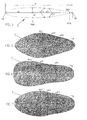
- FIGS. 5 to 7 Embodiments of cross-sectional profiles of panels 7, in which the position of the maximum thickness PMT is different and the trailing edge position PTE is each 95% of the length chord C and the trailing edge thickness TET at this point is between 10 and 65% of the maximum thickness PMT (0, 10 ⁇ TET / MT ⁇ 0.65).
Landscapes
- Engineering & Computer Science (AREA)
- Mechanical Engineering (AREA)
- General Engineering & Computer Science (AREA)
- Structures Of Non-Positive Displacement Pumps (AREA)
Abstract
Description
Die Erfindung betrifft ein aerodynamisch geformtes, symmetrisches Querschnittsprofil für die Stützen oder die Verkleidung von Stützen und Versorgungsleitungen im Neben- und Kernstromkanal eines Turbofantriebwerks.The invention relates to an aerodynamically shaped, symmetrical cross-sectional profile for the supports or the lining of columns and supply lines in the secondary and core flow channel of a turbofan engine.
Turbofantriebwerke weisen am Lufteintritt einen Fan (oder Bläser) auf, hinter dem der von diesem erzeugte Luftstrom in einen Kernluftstrom und einen Nebenluftstrom aufgeteilt wird. Der Kernluftstrom strömt in einem Kernstromkanal, der von einem den Nebenluftstrom führenden Nebenstromkanal umgeben ist. Die von der Triebwerksverkleidung gebildete Außenwand des Nebenstromkanals ist durch sich radial erstreckende Stützelemente an der Seitenwand des Kernstromkanals, die gleichzeitig die Innenwand des Nebenstromkanals bildet, abgestützt. Darüber hinaus befinden sich im Nebenstromkanal in radialer Richtung verlaufende Versorgungsleitungen für die Flugzeugzelle und für das Triebwerk, die einzeln oder als Gruppe mit aerodynamisch geformten Verkleidungselementen ummantelt sind. Die Stützelemente sind ebenfalls von einem aerodynamisch geformten Verkleidungselement umgeben oder weisen ein aerodynamisch geformtes Querschnittsprofil auf. Auch im Kernstromkanal des Triebwerks sind Stützelemente angeordnet, die aerodynamisch verkleidet sind oder selbst ein aerodynamisch geformtes Profil aufweisen können. Durch die aerodynamische Form der Verkleidung oder der Stützen selbst sollen die Druckverluste im Nebenstromkanal und Kernstromkanal reduziert und Vibrationen und damit verbundene mechanisch und akustisch nachteilige Wirkungen verringert werden. Die aerodynamische Formgebung der Stütz- und Verkleidungselemente stimmt nahezu oder vollständig mit der Form der bekanntermaßen verwendeten sogenannten NACA-Profile überein, die als der lokale Dickenverlauf entlang der Sehne des Querschnittsprofils definiert werden. Zwar sind die Druckverluste bei der Anordnung von Verkleidungselementen geringer als ohne Verkleidung, jedoch kann es trotz aerodynamischer Formgebung aufgrund des relativ großen Volumens der Verkleidungselemente oder der aerodynamisch geformten Stützen zu erheblichen Druckverlusten und Nachläufen kommen, die der Erzielung einer optimalen Triebwerksleistung und eines geringen Kraftstoffverbrauches sowie einer Minimierung von Vibrationen und der Schallemission entgegenstehen.Turbofan engines have at the air inlet to a fan (or fan), behind which the air flow generated by this is divided into a core air flow and a secondary air flow. The core air stream flows in a core flow channel, which is surrounded by a bypass air channel leading to the secondary air flow. The outer wall of the bypass duct formed by the engine cowling is supported by radially extending support members on the side wall of the core flow passage which simultaneously forms the inner wall of the bypass duct. In addition, in the bypass duct are radially extending supply lines for the airframe and for the engine, which are sheathed individually or in a group with aerodynamically shaped cladding elements. The support elements are also surrounded by an aerodynamically shaped cladding element or have an aerodynamically shaped cross-sectional profile. Also in the core flow channel of the engine supporting elements are arranged, which are aerodynamically clad or even have an aerodynamically shaped profile. The aerodynamic shape of the cladding or of the supports themselves is intended to reduce the pressure losses in the bypass duct and the core flow duct and to reduce vibrations and the associated mechanically and acoustically disadvantageous effects. The aerodynamic design of the support and cladding elements Almost or completely coincides with the shape of the so-called NACA profiles known to be used, which are defined as the local thickness profile along the chord of the cross-sectional profile. Although the pressure losses in the arrangement of cladding elements are lower than without cladding, but it can despite aerodynamic design due to the relatively large volume of the cladding elements or the aerodynamically shaped supports come to significant pressure drops and overruns, the achievement of optimum engine performance and low fuel consumption and a minimization of vibrations and the noise emission oppose.
Der Erfindung liegt die Aufgabe zugrunde, ein aerodynamisch geformtes Querschnittsprofil für die Stützen oder die Verkleidung von Stützen und Versorgungsleitungen im Nebenstromkanal und für die Stützen im Kernstromkanal eines Turbofantriebwerks anzugeben, das eine Verminderung der Druckverluste, der Schallemission und der Vibrationen bewirkt.The invention has for its object to provide an aerodynamically shaped cross-sectional profile for the columns or the lining of columns and supply lines in the bypass channel and for the supports in the core flow channel of a turbofan engine, which causes a reduction in pressure losses, noise emission and vibration.
Erfindungsgemäß wird die Aufgabe mit einem gemäß den Merkmalen des Patentanspruchs 1 gestalteten Querschnittsprofil gelöst. Zweckmäßige Weiterbildungen der Erfindung sind Gegenstand der Unteransprüche.According to the invention the object is achieved with a designed according to the features of claim 1 cross-sectional profile. Advantageous developments of the invention are the subject of the dependent claims.
Ausgehend von einem aerodynamischen Querschnittsprofil das durch einen jeweiligen Verlauf der lokalen Dicke und eine jeweilige Position der maximalen Dicke beidseitig über der sich von der Vorderkante bis zur Hinterkante der Stütze oder Verkleidung erstreckenden zentralen Sehne bestimmt ist, besteht der Grundgedanke der Erfindung darin, dass der Verlauf der lokalen Dicke zwischen der Position der maximalen Dicke und einer bestimmten, bei 95% der Sehnenlänge liegenden Hinterkantenposition einen ersten Wendepunkt (WP1) und einen anschließenden zweiten Wendepunkt (WP2) aufweist. Aufgrund der in diesem vorgegebenen Bereich liegenden Wendepunkte im Verlauf der lokalen Dicke werden Strömungsablösungen verhindert oder derart minimiert, das Druckverluste und der dadurch bedingte höhere Kraftstoffverbrauch sowie die Schallemission und Vibrationen verringert werden können.Starting from an aerodynamic cross-sectional profile which is determined by a respective profile of the local thickness and a respective position of maximum thickness on both sides over the central chord extending from the leading edge to the trailing edge of the support or shroud, the basic idea of the invention is that the course the local thickness between the position of the maximum thickness and a certain, lying at 95% of the chord length trailing edge position a first Turning point (WP1) and a subsequent second turning point (WP2) has. Because of the inflection points in the given region in the course of the local thickness, flow separations are prevented or minimized in such a way that the pressure losses and the resulting higher fuel consumption as well as the noise emission and vibrations can be reduced.
In weiterer Ausbildung der Erfindung ist der Verlauf der lokalen Dicke im Bereich der Wendepunkte so gestaltet, dass ausgehend von der Position der maximalen Dicke der zunächst negative Gradient des Verlaufs der lokalen Dicke im ersten Wendepunkt geringer oder Null oder positiv wird und entsprechend dem vorhergehenden Gradienten im zweiten Wendepunkt entweder zunehmend negativ oder negativ oder abnehmend positiv wird.In a further embodiment of the invention, the profile of the local thickness in the region of the inflection points is designed so that starting from the position of the maximum thickness of the first negative gradient of the course of the local thickness in the first inflection point is lower or zero or positive and corresponding to the previous gradient in second turning point is either increasingly negative or negative or decreasing positive.
In weiterer Ausbildung der Erfindung hat die Hinterkantendicke in der Hinterkantenposition einen Wert zwischen 10% und 65% der maximalen Dicke.In a further embodiment of the invention, the trailing edge thickness in the trailing edge position has a value between 10% and 65% of the maximum thickness.
Die lokale Dicke im ersten Wendepunkt ist immer kleiner als die maximale Dicke und im zweiten Wendepunkt immer größer als die Hinterkantendicke in der HinterkantenpositionThe local thickness in the first inflection point is always smaller than the maximum thickness and in the second inflection point always greater than the trailing edge thickness in the trailing edge position
Der Verlauf der lokalen Dicke bis zur maximalen Dicke, die Position der maximalen Dicke die maximale Dicke selbst sowie der Ort der Anordnung der Wendepunkte zwischen der Position der maximalen Dicke und der Hinterkantenposition können beliebig gestaltet sein.The course of the local thickness to the maximum thickness, the position of the maximum thickness, the maximum thickness itself as well as the location of the arrangement of the inflection points between the position of the maximum thickness and the trailing edge position can be designed as desired.
Ein Ausführungsbeispiel der Erfindung wird anhand der Zeichnung näher erläutert. Es zeigen:
- Fig. 1
- eine stark vereinfachte schematische Schnittansicht eines Turbofantriebwerks in zwei unterschiedlichen Ausführungsvarianten des Nebenstromkanals;
- Fig. 2
- eine schematische Darstellung von im Neben- stromkanal als Bündel angeordneten, mit ei- ner herkömmlichen Verkleidung umhüllten Ver- sorgungsrohren und -leitungen;
- Fig. 3
- eine Darstellung zur Definition des Querschnittsprofils für eine Stütze oder ei- ne Verkleidung;
- Fig. 4
- den Dickenverlauf bei einem gemäß
Fig. 3 definierten Querschnittsprofil; und - Fig. 5 - 7
- verschiedene Ausführungsformen von Querschnittsprofilen von Stützen oder Ver- kleidungen.
- Fig. 1
- a highly simplified schematic sectional view of a turbofan engine in two different variants of the bypass duct;
- Fig. 2
- a schematic representation of arranged in the bypass channel as a bundle, with a conventional cladding covered supply pipes and pipes;
- Fig. 3
- a representation for defining the cross-sectional profile for a support or a cladding;
- Fig. 4
- the course of thickness in accordance with
Fig. 3 defined cross-sectional profile; and - Fig. 5-7
- various embodiments of cross-sectional profiles of columns or linings.
Das in
Das Querschnittsprofil der Verkleidung 7 ist durch eine sich zwischen der Vorderkante LE und der Hinterkante TE erstreckende Sehne C und den Verlauf der lokalen Dicke T über der Sehnenlänge sowie eine maximale Dicke MT in einer Position PMT (Position der maximalen Dicke) und eine Hinterkantendicke TET in einer Hinterkantenposition PTE (Position der Hinterkantendicke) definiert. Der Abstand, das heißt die Teilsehnenlänge, zwischen der Position der maximalen Dicke PMT und der Vorderkante LE bzw. der Hinterkante TE wird mit CL bzw. CT bezeichnet.The cross-sectional profile of the
Der Verlauf der lokalen Dicke T entlang der Sehne C von der Vorderkante LE bis zur maximalen Dicke MT in der Position PMT ist in herkömmlicher Weise gestaltet. Das gilt gleichermaßen für den Verlauf der lokalen Dicke T zwischen der Hinterkantenposition PTE und der Hinterkante TE. Die Hinterkantenposition PTE ist auf 95% der Länge der Sehne C des Querschnittsprofils festgelegt und die lokale Dicke T in dieser Position, das heißt die Hinterkantendicke TET, liegt im Bereich von 10% bis 65% der maximalen Dicke (0,10<TET/MT<0,65). In dem Verlauf der lokalen Dicke T zwischen der - beliebig angeordneten - Position der maximalen Dicke PMT und der festgelegten Hinterkantenposition PTE sind an beliebiger Stelle - wie beispielhaft in
Während der Verlauf der lokalen Dicke T in
- 11
- TriebwerksverkleidungEngine cowling
- 22
- innere Seitenwandinner sidewall
- 33
- NebenstromkanalBypass duct
- 44
- KernstromkanalCore flow duct
- 55
- Einlassinlet
- 66
- Fanfan
- 77
- Verkleidungpaneling
- 88th
- StützenSupport
- 99
- Versorgungsleitungensupply lines
- 1010
- Brennkammercombustion chamber
- CC
- Sehnetendon
- TT
- lokale Dicke über Clocal thickness over C
- MTMT
- maximale Dickemaximum thickness
- TETTET
- HinterkantendickeTrailing edge thickness
- PMTPMT
- Position der maximalen DickePosition of maximum thickness
- PTEPTE
- HinterkantenpositionTrailing edge position
- LELE
- Vorderkante von 7Leading edge of 7
- TETE
- Hinterkante von 7Trailing edge of 7
- CLCL
- Sehnenlänge zwischen LE und PMTChord length between LE and PMT
- CTCT
- Sehnenlänge zwischen PMT und TEChord length between PMT and TE
- WP1WP1
- erster Wendepunktfirst turning point
- WP2WP2
- zweiter Wendepunktsecond turning point
Claims (6)
Applications Claiming Priority (1)
| Application Number | Priority Date | Filing Date | Title |
|---|---|---|---|
| DE102009034530A DE102009034530A1 (en) | 2009-07-23 | 2009-07-23 | Cross-sectional profile for the columns or the lining of columns and supply lines of a turbofan engine |
Publications (3)
| Publication Number | Publication Date |
|---|---|
| EP2282011A2 true EP2282011A2 (en) | 2011-02-09 |
| EP2282011A3 EP2282011A3 (en) | 2014-07-02 |
| EP2282011B1 EP2282011B1 (en) | 2018-02-28 |
Family
ID=42537779
Family Applications (1)
| Application Number | Title | Priority Date | Filing Date |
|---|---|---|---|
| EP10007454.1A Not-in-force EP2282011B1 (en) | 2009-07-23 | 2010-07-19 | Cross-sectional profile of the supports or of the cover of the supports with supply lines of a Turbofan |
Country Status (3)
| Country | Link |
|---|---|
| US (1) | US8523517B2 (en) |
| EP (1) | EP2282011B1 (en) |
| DE (1) | DE102009034530A1 (en) |
Cited By (1)
| Publication number | Priority date | Publication date | Assignee | Title |
|---|---|---|---|---|
| CN109747575A (en) * | 2018-12-05 | 2019-05-14 | 江苏大学 | A multi-mode interior sound quality optimization system based on order optimization |
Families Citing this family (12)
| Publication number | Priority date | Publication date | Assignee | Title |
|---|---|---|---|---|
| DE102010027588A1 (en) | 2010-07-19 | 2012-01-19 | Rolls-Royce Deutschland Ltd & Co Kg | Fan-Nachleitradschaufel a turbofan engine |
| DE102011013076A1 (en) | 2011-03-04 | 2012-09-06 | Rolls-Royce Deutschland Ltd & Co Kg | Jet engine device with a bypass duct |
| US10309236B2 (en) * | 2013-03-14 | 2019-06-04 | Rolls-Royce Corporation | Subsonic shock strut |
| US9644497B2 (en) | 2013-11-22 | 2017-05-09 | Siemens Energy, Inc. | Industrial gas turbine exhaust system with splined profile tail cone |
| US9587519B2 (en) | 2013-11-22 | 2017-03-07 | Siemens Energy, Inc. | Modular industrial gas turbine exhaust system |
| US9540956B2 (en) | 2013-11-22 | 2017-01-10 | Siemens Energy, Inc. | Industrial gas turbine exhaust system with modular struts and collars |
| US9512740B2 (en) | 2013-11-22 | 2016-12-06 | Siemens Energy, Inc. | Industrial gas turbine exhaust system with area ruled exhaust path |
| US9598981B2 (en) | 2013-11-22 | 2017-03-21 | Siemens Energy, Inc. | Industrial gas turbine exhaust system diffuser inlet lip |
| US10562626B2 (en) * | 2014-03-03 | 2020-02-18 | Robert N. Dunn | Tandem wing aircraft with variable lift and enhanced safety |
| US10508549B2 (en) * | 2014-06-06 | 2019-12-17 | United Technologies Corporation | Gas turbine engine airfoil with large thickness properties |
| US20180045221A1 (en) * | 2016-08-15 | 2018-02-15 | General Electric Company | Strut for an aircraft engine |
| US11248478B2 (en) * | 2018-06-07 | 2022-02-15 | Siemens Aktiengesellschaft | Turbine exhaust crack mitigation using partial collars |
Family Cites Families (9)
| Publication number | Priority date | Publication date | Assignee | Title |
|---|---|---|---|---|
| US3403889A (en) * | 1966-04-07 | 1968-10-01 | Gen Electric | Frame assembly having low thermal stresses |
| US5020318A (en) * | 1987-11-05 | 1991-06-04 | General Electric Company | Aircraft engine frame construction |
| US5203163A (en) * | 1990-08-01 | 1993-04-20 | General Electric Company | Heat exchange arrangement in a gas turbine engine fan duct for cooling hot bleed air |
| US6334753B1 (en) * | 2000-07-31 | 2002-01-01 | United Technologies Corporation | Streamlined bodies with counter-flow fluid injection |
| US7316539B2 (en) * | 2005-04-07 | 2008-01-08 | Siemens Power Generation, Inc. | Vane assembly with metal trailing edge segment |
| FR2891301B1 (en) * | 2005-09-29 | 2007-11-02 | Snecma Sa | STRUCTURAL CASING OF TURBOMOTEUR |
| DE102007020025A1 (en) * | 2007-04-27 | 2008-10-30 | Honda Motor Co., Ltd. | Shape of a gas channel in an axial flow gas turbine engine |
| US8029234B2 (en) * | 2007-07-24 | 2011-10-04 | United Technologies Corp. | Systems and methods involving aerodynamic struts |
| US7946806B2 (en) * | 2007-10-10 | 2011-05-24 | United Technologies Corporation | Gas turbine engine systems and related methods involving heat exchange |
-
2009
- 2009-07-23 DE DE102009034530A patent/DE102009034530A1/en not_active Withdrawn
-
2010
- 2010-07-14 US US12/836,385 patent/US8523517B2/en not_active Expired - Fee Related
- 2010-07-19 EP EP10007454.1A patent/EP2282011B1/en not_active Not-in-force
Non-Patent Citations (1)
| Title |
|---|
| None |
Cited By (2)
| Publication number | Priority date | Publication date | Assignee | Title |
|---|---|---|---|---|
| CN109747575A (en) * | 2018-12-05 | 2019-05-14 | 江苏大学 | A multi-mode interior sound quality optimization system based on order optimization |
| CN109747575B (en) * | 2018-12-05 | 2021-05-25 | 江苏大学 | Multi-mode in-vehicle sound quality optimization system based on order optimization |
Also Published As
| Publication number | Publication date |
|---|---|
| EP2282011B1 (en) | 2018-02-28 |
| US8523517B2 (en) | 2013-09-03 |
| DE102009034530A1 (en) | 2011-01-27 |
| EP2282011A3 (en) | 2014-07-02 |
| US20110016883A1 (en) | 2011-01-27 |
Similar Documents
| Publication | Publication Date | Title |
|---|---|---|
| EP2282011B1 (en) | Cross-sectional profile of the supports or of the cover of the supports with supply lines of a Turbofan | |
| EP2378072A2 (en) | Bypass flow channel of a turbofan engine | |
| DE69408208T2 (en) | Jet engine | |
| DE602005001519T2 (en) | Noise reduction arrangement for aircraft gas turbine | |
| DE60316487T2 (en) | Corrugated cover for a combustion chamber of a gas turbine and its manufacturing process | |
| DE102009011924A1 (en) | Bypass duct of a turbofan engine | |
| EP2824284A1 (en) | Turbofan engine | |
| CH702552A2 (en) | Silencer for a gas turbine. | |
| DE102010002394A1 (en) | Bypass duct of a turbofan engine | |
| DE102011013076A1 (en) | Jet engine device with a bypass duct | |
| DE102007036527A1 (en) | Nozzle arrangement for a gas turbine engine | |
| DE102015213625A1 (en) | Diffuser component for a gas turbine | |
| DE102017115644A1 (en) | Turbofan | |
| DE102016104957A1 (en) | Cooling device for cooling platforms of a vane ring of a gas turbine | |
| DE112014003991B4 (en) | Heat shield for an exhaust gas turbocharger and exhaust gas turbocharger and a method for producing a heat shield | |
| DE102008019156A1 (en) | Strut for a turbine intermediate housing, turbine intermediate housing and method for producing a turbine intermediate housing | |
| EP2429895B1 (en) | Fairing for a high-lift device | |
| DE102010002395B4 (en) | Turbofan engine with guide vanes and support struts arranged in the bypass duct | |
| EP1632648B1 (en) | Gas turbine with transition duct | |
| DE102009007843A1 (en) | Compressor wheel for exhaust gas turbocharger, has split blades arranged between two consecutive complete blades, where blade periods comprise four blades such as one complete blade and three split blades | |
| EP2365199A2 (en) | Aerodynamically shaped support and/or cladding element in the bypass of a gas turbine engine | |
| DE102020112687B4 (en) | Engine nacelle for a gas turbine engine | |
| EP3266714A1 (en) | Nacelle | |
| DE1576762A1 (en) | Air injector for air-cooled silencers for jet engines | |
| DE102019202072A1 (en) | Engine assembly with cover part |
Legal Events
| Date | Code | Title | Description |
|---|---|---|---|
| PUAI | Public reference made under article 153(3) epc to a published international application that has entered the european phase |
Free format text: ORIGINAL CODE: 0009012 |
|
| AK | Designated contracting states |
Kind code of ref document: A2 Designated state(s): AL AT BE BG CH CY CZ DE DK EE ES FI FR GB GR HR HU IE IS IT LI LT LU LV MC MK MT NL NO PL PT RO SE SI SK SM TR |
|
| AX | Request for extension of the european patent |
Extension state: BA ME RS |
|
| PUAL | Search report despatched |
Free format text: ORIGINAL CODE: 0009013 |
|
| AK | Designated contracting states |
Kind code of ref document: A3 Designated state(s): AL AT BE BG CH CY CZ DE DK EE ES FI FR GB GR HR HU IE IS IT LI LT LU LV MC MK MT NL NO PL PT RO SE SI SK SM TR |
|
| AX | Request for extension of the european patent |
Extension state: BA ME RS |
|
| RIC1 | Information provided on ipc code assigned before grant |
Ipc: F01D 9/00 20060101AFI20140523BHEP Ipc: F01D 25/16 20060101ALI20140523BHEP Ipc: B64D 29/06 20060101ALI20140523BHEP |
|
| 17P | Request for examination filed |
Effective date: 20140716 |
|
| RBV | Designated contracting states (corrected) |
Designated state(s): AL AT BE BG CH CY CZ DE DK EE ES FI FR GB GR HR HU IE IS IT LI LT LU LV MC MK MT NL NO PL PT RO SE SI SK SM TR |
|
| 17Q | First examination report despatched |
Effective date: 20170329 |
|
| GRAP | Despatch of communication of intention to grant a patent |
Free format text: ORIGINAL CODE: EPIDOSNIGR1 |
|
| INTG | Intention to grant announced |
Effective date: 20170922 |
|
| GRAJ | Information related to disapproval of communication of intention to grant by the applicant or resumption of examination proceedings by the epo deleted |
Free format text: ORIGINAL CODE: EPIDOSDIGR1 |
|
| GRAR | Information related to intention to grant a patent recorded |
Free format text: ORIGINAL CODE: EPIDOSNIGR71 |
|
| GRAS | Grant fee paid |
Free format text: ORIGINAL CODE: EPIDOSNIGR3 |
|
| INTC | Intention to grant announced (deleted) | ||
| GRAA | (expected) grant |
Free format text: ORIGINAL CODE: 0009210 |
|
| AK | Designated contracting states |
Kind code of ref document: B1 Designated state(s): AL AT BE BG CH CY CZ DE DK EE ES FI FR GB GR HR HU IE IS IT LI LT LU LV MC MK MT NL NO PL PT RO SE SI SK SM TR |
|
| INTG | Intention to grant announced |
Effective date: 20180123 |
|
| REG | Reference to a national code |
Ref country code: GB Ref legal event code: FG4D Free format text: NOT ENGLISH Ref country code: CH Ref legal event code: EP |
|
| REG | Reference to a national code |
Ref country code: AT Ref legal event code: REF Ref document number: 974372 Country of ref document: AT Kind code of ref document: T Effective date: 20180315 |
|
| REG | Reference to a national code |
Ref country code: IE Ref legal event code: FG4D Free format text: LANGUAGE OF EP DOCUMENT: GERMAN |
|
| REG | Reference to a national code |
Ref country code: DE Ref legal event code: R096 Ref document number: 502010014695 Country of ref document: DE |
|
| REG | Reference to a national code |
Ref country code: NL Ref legal event code: MP Effective date: 20180228 |
|
| REG | Reference to a national code |
Ref country code: LT Ref legal event code: MG4D |
|
| REG | Reference to a national code |
Ref country code: FR Ref legal event code: PLFP Year of fee payment: 9 |
|
| PG25 | Lapsed in a contracting state [announced via postgrant information from national office to epo] |
Ref country code: LT Free format text: LAPSE BECAUSE OF FAILURE TO SUBMIT A TRANSLATION OF THE DESCRIPTION OR TO PAY THE FEE WITHIN THE PRESCRIBED TIME-LIMIT Effective date: 20180228 Ref country code: CY Free format text: LAPSE BECAUSE OF FAILURE TO SUBMIT A TRANSLATION OF THE DESCRIPTION OR TO PAY THE FEE WITHIN THE PRESCRIBED TIME-LIMIT Effective date: 20180228 Ref country code: NL Free format text: LAPSE BECAUSE OF FAILURE TO SUBMIT A TRANSLATION OF THE DESCRIPTION OR TO PAY THE FEE WITHIN THE PRESCRIBED TIME-LIMIT Effective date: 20180228 Ref country code: FI Free format text: LAPSE BECAUSE OF FAILURE TO SUBMIT A TRANSLATION OF THE DESCRIPTION OR TO PAY THE FEE WITHIN THE PRESCRIBED TIME-LIMIT Effective date: 20180228 Ref country code: ES Free format text: LAPSE BECAUSE OF FAILURE TO SUBMIT A TRANSLATION OF THE DESCRIPTION OR TO PAY THE FEE WITHIN THE PRESCRIBED TIME-LIMIT Effective date: 20180228 Ref country code: NO Free format text: LAPSE BECAUSE OF FAILURE TO SUBMIT A TRANSLATION OF THE DESCRIPTION OR TO PAY THE FEE WITHIN THE PRESCRIBED TIME-LIMIT Effective date: 20180528 Ref country code: HR Free format text: LAPSE BECAUSE OF FAILURE TO SUBMIT A TRANSLATION OF THE DESCRIPTION OR TO PAY THE FEE WITHIN THE PRESCRIBED TIME-LIMIT Effective date: 20180228 |
|
| PG25 | Lapsed in a contracting state [announced via postgrant information from national office to epo] |
Ref country code: SE Free format text: LAPSE BECAUSE OF FAILURE TO SUBMIT A TRANSLATION OF THE DESCRIPTION OR TO PAY THE FEE WITHIN THE PRESCRIBED TIME-LIMIT Effective date: 20180228 Ref country code: LV Free format text: LAPSE BECAUSE OF FAILURE TO SUBMIT A TRANSLATION OF THE DESCRIPTION OR TO PAY THE FEE WITHIN THE PRESCRIBED TIME-LIMIT Effective date: 20180228 Ref country code: BG Free format text: LAPSE BECAUSE OF FAILURE TO SUBMIT A TRANSLATION OF THE DESCRIPTION OR TO PAY THE FEE WITHIN THE PRESCRIBED TIME-LIMIT Effective date: 20180528 Ref country code: GR Free format text: LAPSE BECAUSE OF FAILURE TO SUBMIT A TRANSLATION OF THE DESCRIPTION OR TO PAY THE FEE WITHIN THE PRESCRIBED TIME-LIMIT Effective date: 20180529 |
|
| PG25 | Lapsed in a contracting state [announced via postgrant information from national office to epo] |
Ref country code: MT Free format text: LAPSE BECAUSE OF FAILURE TO SUBMIT A TRANSLATION OF THE DESCRIPTION OR TO PAY THE FEE WITHIN THE PRESCRIBED TIME-LIMIT Effective date: 20180228 |
|
| PG25 | Lapsed in a contracting state [announced via postgrant information from national office to epo] |
Ref country code: PL Free format text: LAPSE BECAUSE OF FAILURE TO SUBMIT A TRANSLATION OF THE DESCRIPTION OR TO PAY THE FEE WITHIN THE PRESCRIBED TIME-LIMIT Effective date: 20180228 Ref country code: EE Free format text: LAPSE BECAUSE OF FAILURE TO SUBMIT A TRANSLATION OF THE DESCRIPTION OR TO PAY THE FEE WITHIN THE PRESCRIBED TIME-LIMIT Effective date: 20180228 Ref country code: IT Free format text: LAPSE BECAUSE OF FAILURE TO SUBMIT A TRANSLATION OF THE DESCRIPTION OR TO PAY THE FEE WITHIN THE PRESCRIBED TIME-LIMIT Effective date: 20180228 Ref country code: AL Free format text: LAPSE BECAUSE OF FAILURE TO SUBMIT A TRANSLATION OF THE DESCRIPTION OR TO PAY THE FEE WITHIN THE PRESCRIBED TIME-LIMIT Effective date: 20180228 Ref country code: RO Free format text: LAPSE BECAUSE OF FAILURE TO SUBMIT A TRANSLATION OF THE DESCRIPTION OR TO PAY THE FEE WITHIN THE PRESCRIBED TIME-LIMIT Effective date: 20180228 |
|
| REG | Reference to a national code |
Ref country code: DE Ref legal event code: R097 Ref document number: 502010014695 Country of ref document: DE |
|
| PG25 | Lapsed in a contracting state [announced via postgrant information from national office to epo] |
Ref country code: SK Free format text: LAPSE BECAUSE OF FAILURE TO SUBMIT A TRANSLATION OF THE DESCRIPTION OR TO PAY THE FEE WITHIN THE PRESCRIBED TIME-LIMIT Effective date: 20180228 Ref country code: SM Free format text: LAPSE BECAUSE OF FAILURE TO SUBMIT A TRANSLATION OF THE DESCRIPTION OR TO PAY THE FEE WITHIN THE PRESCRIBED TIME-LIMIT Effective date: 20180228 Ref country code: DK Free format text: LAPSE BECAUSE OF FAILURE TO SUBMIT A TRANSLATION OF THE DESCRIPTION OR TO PAY THE FEE WITHIN THE PRESCRIBED TIME-LIMIT Effective date: 20180228 Ref country code: CZ Free format text: LAPSE BECAUSE OF FAILURE TO SUBMIT A TRANSLATION OF THE DESCRIPTION OR TO PAY THE FEE WITHIN THE PRESCRIBED TIME-LIMIT Effective date: 20180228 |
|
| PLBE | No opposition filed within time limit |
Free format text: ORIGINAL CODE: 0009261 |
|
| STAA | Information on the status of an ep patent application or granted ep patent |
Free format text: STATUS: NO OPPOSITION FILED WITHIN TIME LIMIT |
|
| 26N | No opposition filed |
Effective date: 20181129 |
|
| PG25 | Lapsed in a contracting state [announced via postgrant information from national office to epo] |
Ref country code: SI Free format text: LAPSE BECAUSE OF FAILURE TO SUBMIT A TRANSLATION OF THE DESCRIPTION OR TO PAY THE FEE WITHIN THE PRESCRIBED TIME-LIMIT Effective date: 20180228 |
|
| REG | Reference to a national code |
Ref country code: CH Ref legal event code: PL |
|
| PG25 | Lapsed in a contracting state [announced via postgrant information from national office to epo] |
Ref country code: MC Free format text: LAPSE BECAUSE OF FAILURE TO SUBMIT A TRANSLATION OF THE DESCRIPTION OR TO PAY THE FEE WITHIN THE PRESCRIBED TIME-LIMIT Effective date: 20180228 Ref country code: LU Free format text: LAPSE BECAUSE OF NON-PAYMENT OF DUE FEES Effective date: 20180719 |
|
| REG | Reference to a national code |
Ref country code: BE Ref legal event code: MM Effective date: 20180731 |
|
| REG | Reference to a national code |
Ref country code: IE Ref legal event code: MM4A |
|
| PG25 | Lapsed in a contracting state [announced via postgrant information from national office to epo] |
Ref country code: LI Free format text: LAPSE BECAUSE OF NON-PAYMENT OF DUE FEES Effective date: 20180731 Ref country code: CH Free format text: LAPSE BECAUSE OF NON-PAYMENT OF DUE FEES Effective date: 20180731 Ref country code: IE Free format text: LAPSE BECAUSE OF NON-PAYMENT OF DUE FEES Effective date: 20180719 |
|
| PG25 | Lapsed in a contracting state [announced via postgrant information from national office to epo] |
Ref country code: BE Free format text: LAPSE BECAUSE OF NON-PAYMENT OF DUE FEES Effective date: 20180731 |
|
| REG | Reference to a national code |
Ref country code: AT Ref legal event code: MM01 Ref document number: 974372 Country of ref document: AT Kind code of ref document: T Effective date: 20180719 |
|
| PGFP | Annual fee paid to national office [announced via postgrant information from national office to epo] |
Ref country code: DE Payment date: 20190729 Year of fee payment: 10 Ref country code: FR Payment date: 20190725 Year of fee payment: 10 |
|
| PG25 | Lapsed in a contracting state [announced via postgrant information from national office to epo] |
Ref country code: AT Free format text: LAPSE BECAUSE OF NON-PAYMENT OF DUE FEES Effective date: 20180719 |
|
| PGFP | Annual fee paid to national office [announced via postgrant information from national office to epo] |
Ref country code: GB Payment date: 20190729 Year of fee payment: 10 |
|
| PG25 | Lapsed in a contracting state [announced via postgrant information from national office to epo] |
Ref country code: TR Free format text: LAPSE BECAUSE OF FAILURE TO SUBMIT A TRANSLATION OF THE DESCRIPTION OR TO PAY THE FEE WITHIN THE PRESCRIBED TIME-LIMIT Effective date: 20180228 |
|
| PG25 | Lapsed in a contracting state [announced via postgrant information from national office to epo] |
Ref country code: HU Free format text: LAPSE BECAUSE OF FAILURE TO SUBMIT A TRANSLATION OF THE DESCRIPTION OR TO PAY THE FEE WITHIN THE PRESCRIBED TIME-LIMIT; INVALID AB INITIO Effective date: 20100719 Ref country code: PT Free format text: LAPSE BECAUSE OF FAILURE TO SUBMIT A TRANSLATION OF THE DESCRIPTION OR TO PAY THE FEE WITHIN THE PRESCRIBED TIME-LIMIT Effective date: 20180228 |
|
| PG25 | Lapsed in a contracting state [announced via postgrant information from national office to epo] |
Ref country code: MK Free format text: LAPSE BECAUSE OF NON-PAYMENT OF DUE FEES Effective date: 20180228 |
|
| PG25 | Lapsed in a contracting state [announced via postgrant information from national office to epo] |
Ref country code: IS Free format text: LAPSE BECAUSE OF FAILURE TO SUBMIT A TRANSLATION OF THE DESCRIPTION OR TO PAY THE FEE WITHIN THE PRESCRIBED TIME-LIMIT Effective date: 20180628 |
|
| REG | Reference to a national code |
Ref country code: DE Ref legal event code: R082 Ref document number: 502010014695 Country of ref document: DE |
|
| REG | Reference to a national code |
Ref country code: DE Ref legal event code: R119 Ref document number: 502010014695 Country of ref document: DE |
|
| GBPC | Gb: european patent ceased through non-payment of renewal fee |
Effective date: 20200719 |
|
| PG25 | Lapsed in a contracting state [announced via postgrant information from national office to epo] |
Ref country code: FR Free format text: LAPSE BECAUSE OF NON-PAYMENT OF DUE FEES Effective date: 20200731 Ref country code: GB Free format text: LAPSE BECAUSE OF NON-PAYMENT OF DUE FEES Effective date: 20200719 |
|
| PG25 | Lapsed in a contracting state [announced via postgrant information from national office to epo] |
Ref country code: DE Free format text: LAPSE BECAUSE OF NON-PAYMENT OF DUE FEES Effective date: 20210202 |