EP2282015B1 - Turbomachine avec joint amélioré - Google Patents
Turbomachine avec joint amélioré Download PDFInfo
- Publication number
- EP2282015B1 EP2282015B1 EP09164090.4A EP09164090A EP2282015B1 EP 2282015 B1 EP2282015 B1 EP 2282015B1 EP 09164090 A EP09164090 A EP 09164090A EP 2282015 B1 EP2282015 B1 EP 2282015B1
- Authority
- EP
- European Patent Office
- Prior art keywords
- seal
- rotor
- row
- guide vane
- fluid flow
- Prior art date
- Legal status (The legal status is an assumption and is not a legal conclusion. Google has not performed a legal analysis and makes no representation as to the accuracy of the status listed.)
- Active
Links
Images



Classifications
-
- F—MECHANICAL ENGINEERING; LIGHTING; HEATING; WEAPONS; BLASTING
- F01—MACHINES OR ENGINES IN GENERAL; ENGINE PLANTS IN GENERAL; STEAM ENGINES
- F01D—NON-POSITIVE DISPLACEMENT MACHINES OR ENGINES, e.g. STEAM TURBINES
- F01D11/00—Preventing or minimising internal leakage of working-fluid, e.g. between stages
- F01D11/001—Preventing or minimising internal leakage of working-fluid, e.g. between stages for sealing space between stator blade and rotor
-
- F—MECHANICAL ENGINEERING; LIGHTING; HEATING; WEAPONS; BLASTING
- F01—MACHINES OR ENGINES IN GENERAL; ENGINE PLANTS IN GENERAL; STEAM ENGINES
- F01D—NON-POSITIVE DISPLACEMENT MACHINES OR ENGINES, e.g. STEAM TURBINES
- F01D11/00—Preventing or minimising internal leakage of working-fluid, e.g. between stages
- F01D11/02—Preventing or minimising internal leakage of working-fluid, e.g. between stages by non-contact sealings, e.g. of labyrinth type
-
- F—MECHANICAL ENGINEERING; LIGHTING; HEATING; WEAPONS; BLASTING
- F01—MACHINES OR ENGINES IN GENERAL; ENGINE PLANTS IN GENERAL; STEAM ENGINES
- F01D—NON-POSITIVE DISPLACEMENT MACHINES OR ENGINES, e.g. STEAM TURBINES
- F01D11/00—Preventing or minimising internal leakage of working-fluid, e.g. between stages
- F01D11/08—Preventing or minimising internal leakage of working-fluid, e.g. between stages for sealing space between rotor blade tips and stator
-
- F—MECHANICAL ENGINEERING; LIGHTING; HEATING; WEAPONS; BLASTING
- F01—MACHINES OR ENGINES IN GENERAL; ENGINE PLANTS IN GENERAL; STEAM ENGINES
- F01D—NON-POSITIVE DISPLACEMENT MACHINES OR ENGINES, e.g. STEAM TURBINES
- F01D5/00—Blades; Blade-carrying members; Heating, heat-insulating, cooling or antivibration means on the blades or the members
- F01D5/12—Blades
- F01D5/14—Form or construction
- F01D5/20—Specially-shaped blade tips to seal space between tips and stator
Definitions
- Turbo machines such as gas turbines or steam turbines are provided with a stator (made of a plurality of stator parts) enclosing a rotor (that carries a plurality of rotor parts) rotating within it.
- stator parts and the rotor parts are usually provided with labyrinth or brush seals, in order to control and limit the leakage between high and low pressure areas.
- US2007/0237627 and US6059530 disclose a blade with a seal at the tip thereof; the seal is defined by an airfoil profile.
- EP 2116692 A2 teaches a turbine blade comprising a seal with a rotor blade row that extends from an annular plate.
- the technical aim of the present invention is therefore to provide a rotating machine with an improved seal by which the said problems of the known art are eliminated.
- an object of the invention is to provide a rotating machine by which the pressure energy of the fluid is not dissipated and thus wasted.
- the pressure energy of the fluid is not dissipated as heat.
- Another object of the invention is to provide a rotating machine by which the leakage can be regulated independently from the clearance between the stator and rotor parts.
- the gap 4 houses a seal 5 that comprises a guide vane row 6 extending from the stator parts 2 and arranged to guide a fluid flow 7 in the gap 4 and a rotor blade row 14 extending from the rotor part 3 and arranged to exchange mechanical power with the fluid flow 7.
- the guide vane row 6 and rotor blade row 14 maintain the differential pressure between areas at the opposite ends of the seal 5 and prevent the fluid flow 7 from dissipating its pressure energy generating heat.
- the seal 5 also comprises an obstruction arranged to limit the fluid flow 7 through the gap 4.
- the obstruction comprises annular plates 9, 11 and, in this respect, a first annular plate 9 extends transversally from a stator part 2, defining an annular passage 10 for the fluid flow 7 having a prefixed thickness.
- the guide vane row 6 may extend from this stator annular plate 9.
- the seal 5 may define an axial or a radial micro-turbine.
- the pressure energy of the fluid is not dissipated as heat, but is used to provide turbine work thus leading to a decrease of the total temperature of the air (up to 60K per stage). So the rotor and stator temperature are also reduced.
- the seal 5 could have one or more annular plates 9 extending from a stator part 2 and/or one or more annular plates 11 extending from the rotor part 3; the plates 9 and 11 may be placed partly or totally upstream of and/or between and/or downstream of the guide vane row 6 and rotor blade row 14.
- the seal has the rotor blade row 14 followed by the guide vane row 6; nevertheless in different embodiments the guide vane row 6 may not be provided.
- the seal 5 could have one or more annular plates 9 extending from the stator part 2 and/or one or more annular plates 11 extending from the rotor part 3; the plates 9 and 11 may be placed partly or totally upstream of and/or between and/or downstream of the guide vane row 6 and rotor blade row 14.
- micro-turbine and the micro-compressor may have one single stage or multiple stages.
- micro-compressor may be implemented in the bearing areas, (no leakage tolerated), as an axial or radial seal arrangement or in combination with labyrinth or brush seal.
- micro-turbine and micro-compressor are possible.
- the blades can be directly machined on the rotor shaft, rotor disk, blade root, casing, honeycomb at the vane hub, stator heat shield or rotor heat shield. Nevertheless the blades can also be designed on the sealing strips, or be separated attached parts.
- Figure 1 shows an example wherein the seal 5 defines an axial micro-turbine.
- FIG 1 shows a stator part 2 from which the main stator blades 18 defining a plurality of guide vanes extend (i.e. the stator blades 18 are those of the gas or steam turbine).
- Figure 1 also shows a rotor part 3 from which the main rotor blades 16 extend (i.e. the rotor blades 16 are those of the gas or steam turbine).
- a gap 4 is defined between the tip of the stator blades 18 and the rotor part 3 .
- a part of the hot gases (i.e. the fluid flow 7) leaks in the gap 4 and passes through the guide vane row 6 that processes it and drives it towards the main rotor blades 16.
- the mass flow through the gap 4 is defined by the thickness of the gap 4 and the shape of the guide vane row 6 (and naturally also the differential pressure upstream and downstream of the guide vane row 6).
- This example lets further mechanical power be collected by the main rotor blades 16 (the power that in traditional seals is dissipated, in the seal according to this example is collected by the rotor blades 16); thus the local temperatures (in particular those of the air and rotor parts) are reduced with respect to traditional seals, because there is no or less fluid flow pressure energy that is converted into heat.
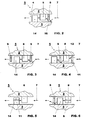
- Figure 2 through 4 show different examples of axial micro-turbines having a guide vane row 6 and a rotor blade row 14.
- figure 2 shows an axial micro-turbine having a stator part 2 and a rotor part 3 defining a gap 4; the stator part 2 supports the guide vane row 6 and the rotor part 3 supports the rotor blade row 14.
- the fluid flow 7 (i.e. the leakage) passes through the passage 10 between the annular plate 9 and the rotor part 3 and passes through the guide vane row 6; then the fluid flow 7 passes through the rotor blade row 14 and delivers mechanical power to the rotor part 3.
- the mass flow of the fluid passing through the gap 4 is defined by the passage 10 (i.e. the annular plate 9) and by the geometry and configuration of the guide vane row 6 and rotor blade row 14.
- figure 3 shows an example of a seal 5 with two annular plates 9 extending from the stator part 2 respectively one upstream of the guide vane row 6, and the other downstream of the rotor blade row 14.
- Figure 4 shows an example of a seal 5 with an annular plate 11 extending from the rotor part 3 upstream of the guide vane row 6 and a further annular plate 9 extending from the stator part 2 between the guide vane row 6 and the rotor blade row 14.
- Figure 5 shows an embodiment of a seal 5 of the invention with a guide vane row 6 extending from the stator part 2 and an annular plate 11 extending from the rotor part 3 downstream of the guide vane row 6 and carrying at its border the rotor blade row 14.
- Figure 6 shows an embodiment of a seal 5 of the invention with an annular plate 9 extending from the stator part 2; from the border of the annular plate 9 the guide vane row 6 extends.
- figure 7 shows a stator part 2 carrying the main stator blades 18 and a rotor part 3 carrying the main rotor blades 16.
- the radial gap 4 is defined, housing an annular plate 11 extending from the rotor part 3 and downstream of it (with respect to the direction of the fluid flow 7) a guide vane row 6 extending (in this embodiment) from an annular plate 9.
- a fluid flow 7 of compressed air (purge air) is injected through the gap 4 towards the hot gases path 20.
- This fluid flow 7 passes through the passage 12 between the border of the annular plate 11 and the stator part 2 and then passes through the guide vane row 6 that prepares the fluid flow 7 to pass through the main rotor blades 16 and drives it towards it.
- the mass flow of the fluid flow 7 is limited by the plate 11 (i.e. the thickness of the passage 12) and the shape and configuration of the guide vane row 6 and annular plate 9.
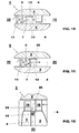
- Figures 8 and 9 show two embodiments of a radial micro-turbine having the guide vane row 6 and the rotor blade row 14.
- figure 8 shows a stator part 2 from which the main stator blades 18 extend and a rotor part 3 from which the main rotor blades 16 extend.
- annular plate 9 extending from the stator part 2 and carrying at its border the guide vane row 6 and downstream of it a rotor blade row 14 extending from the rotor part 3 are housed.
- Figure 9 shows a further embodiment similar to those already described. This embodiment has a guide vane row 6 extending from an annular plate 9 connected to a stator part 2, a rotor blade row 11 and a further annular plate 9.
- Figures 10 through 12 show three example seals defining a micro-compressor; also in these cases the reference numbers are the same as those already used to indicate the same or similar elements.
- figure 10 shows a stator part 2 and a rotor part 3 defining a gap 4.
- the seal 5 upstream of the rotor blade row 14, the seal 5 has an annular plate 9 extending from the stator part 2 and a further annular plate 11 extending from the rotor part 3.
- the fluid flow 7 (initially in the lower pressure area 22) overcomes the annular plates 11 and 9 and then passes through the rotor blade row 14 and thus through the guide vane row 6 to be supplied to the higher pressure area 24.
- the seal 5 can thus be designed in order to have a desired flow from the higher pressure area 24 towards the lower pressure area 22, or no flow at all (i.e. the leakage 25 from the higher pressure area 24 towards the lower pressure area 22 is fully compensated by the flow 7 from the lower pressure area 22 towards the higher pressure area 24).
- the seal 5 can be designed in order to have a reverse flow, i.e. the fluid flow 7 from the lower pressure area 22 towards the higher pressure area 24 is greater than the leakage 25 from the higher pressure area 24 towards the lower pressure area 22.
- the mass flow of the fluid is defined by the annular plates 11 and 9 and by the configuration and shape of the rotor blade row 14 and guide vane row 6.
- the rotor part 3 carries the rotor blade row 14 and, upstream of it, an annular plate 11; between the rotor blade row 14 and annular plate 11 the stator part 2 carries an annular plate 9.
- Figure 12 shows an example of radial micro-compressor.
- stator part 2 carries the main stator blades 18 and a rotor part 3 carries the main rotor blades 16.
- the gap 4 is provided.
- a rotor blade row 14 extends from the rotor part 3 and a guide vane row 6 extends from the stator part 2.
- This example could be used to reduce or eliminate the purge air, i.e. the air injected in the gap 4 to prevent the hot gases flowing in the hot gases path 20 from entering the gap 4.
- the seal 5 could be designed such that a recirculation occurs that keeps the hot gases in the hot gases path 20.
- the mass flow of the fluid is defined by the configuration and shape of the rotor blade row 14 and guide vane row 6.
- the temperature increase is limited, because the amount of energy pressure converted into heat is limited (the energy of the fluid is increased).
Landscapes
- Engineering & Computer Science (AREA)
- Mechanical Engineering (AREA)
- General Engineering & Computer Science (AREA)
- Turbine Rotor Nozzle Sealing (AREA)
- Structures Of Non-Positive Displacement Pumps (AREA)
Claims (7)
- Machine tournante (1) avec joint amélioré comportant des pièces (2) de stator et des pièces (3) de rotor entre lesquelles est ménagé un interstice (4) renfermant au moins un joint (5), ledit joint (5) comportant une rangée (6) d'aubes de guidage, qui s'étend à partir d'une pièce (2) de stator et est disposé de façon à guider un écoulement de fluide, et / ou une rangée (14) d'aubes de rotor, qui s'étend à partir d'une pièce (3) de rotor et est disposé de façon à échanger une puissance mécanique avec l'écoulement de fluide, ladite rangée (6) d'aubes de guidage et / ou ladite rangée (14) d'aubes de rotor maintenant une pression différentielle entre des zones situées à des extrémités opposées du joint (5) et empêchant l'écoulement de fluide de dissiper son énergie de pression en générant de la chaleur, le joint (5) comportant un obstacle (9, 11) disposé de façon à limiter l'écoulement de fluide (7) à travers ledit interstice (4), ladite rangée (6) d'aubes de guidage s'étendant à partir dudit obstacle (9) et / ou ladite rangée (14) d'aubes de rotor s'étendant à partir dudit obstacle (11), caractérisée en ce que ledit joint (5) définit une micro-turbine axiale ou radiale.
- Machine tournante (1) avec joint amélioré comportant des pièces (2) de stator et pièces (3) de rotor entre lesquelles est ménagé un interstice (4) renfermant au moins un joint (5), ledit joint (5) comportant une rangée (6) d'aubes de guidage, qui s'étend à partir d'une pièce (2) de stator et est disposé de façon à guider un écoulement de fluide, et / ou une rangée (14) d'aubes de rotor, qui s'étend à partir d'une pièce (3) de rotor et est disposé de façon à échanger une puissance mécanique avec l'écoulement de fluide, ladite rangée (6) d'aubes de guidage et / ou rangée (14) d'aubes de rotor maintenant une pression différentielle entre des zones situées à des extrémités opposées du joint (5) et empêchant l'écoulement de fluide de dissiper son énergie de pression en générant de la chaleur, le joint (5) comportant an obstacle (9, 11) disposé de façon à limiter l'écoulement de fluide (7) à travers ledit interstice (4), ladite rangée (6) d'aubes de guidage s'étend s'étendant à partir dudit obstacle (9) et / ou ladite rangée (14) d'aubes de rotor s'étendant à partir dudit obstacle (11), caractérisée en ce que ledit joint définit un micro-compresseur axial ou radial.
- Machine tournante (1) selon la revendication 1 ou 2, caractérisé en ce que ledit obstacle (9, 11) comporte une plaque annulaire.
- Machine tournante (1) selon la revendication 3, caractérisé en ce que ladite plaque annulaire (9) s'étend transversalement à partir de la pièce (2) de stator, définissant un passage annulaire préétabli (10) pour l'écoulement de fluide (7).
- Machine tournante (1) selon la revendication 3, caractérisé en ce que ladite plaque annulaire (11) s'étend transversalement à partir de la pièce (3) de rotor, définissant un passage annulaire préétabli (12) pour l'écoulement de fluide (7).
- Machine tournante (1) selon la revendication 1 ou 2, caractérisée en ce qu'il s'agit d'une turbine à gaz ou à vapeur.
- Machine tournante (1) selon la revendication 1 ou 2, caractérisé en ce que les aubes de la rangée (6) d'aubes de guidage et / ou de la rangée (14) d'aubes de rotor présentent une hauteur inférieure à 10 millimètres, de préférence inférieure à 5 millimètres et de façon plus préférable inférieure à 3 millimètres.
Priority Applications (2)
| Application Number | Priority Date | Filing Date | Title |
|---|---|---|---|
| EP09164090.4A EP2282015B1 (fr) | 2009-06-30 | 2009-06-30 | Turbomachine avec joint amélioré |
| CN201010256653.8A CN101936194B (zh) | 2009-06-30 | 2010-06-30 | 具有改进的密封结构的旋转机械 |
Applications Claiming Priority (1)
| Application Number | Priority Date | Filing Date | Title |
|---|---|---|---|
| EP09164090.4A EP2282015B1 (fr) | 2009-06-30 | 2009-06-30 | Turbomachine avec joint amélioré |
Publications (2)
| Publication Number | Publication Date |
|---|---|
| EP2282015A1 EP2282015A1 (fr) | 2011-02-09 |
| EP2282015B1 true EP2282015B1 (fr) | 2013-04-17 |
Family
ID=41401802
Family Applications (1)
| Application Number | Title | Priority Date | Filing Date |
|---|---|---|---|
| EP09164090.4A Active EP2282015B1 (fr) | 2009-06-30 | 2009-06-30 | Turbomachine avec joint amélioré |
Country Status (2)
| Country | Link |
|---|---|
| EP (1) | EP2282015B1 (fr) |
| CN (1) | CN101936194B (fr) |
Families Citing this family (2)
| Publication number | Priority date | Publication date | Assignee | Title |
|---|---|---|---|---|
| CN112832872B (zh) * | 2021-02-03 | 2022-09-06 | 东方电气集团东方汽轮机有限公司 | 一种用于汽轮机的引流回旋式汽封 |
| CN116663265B (zh) * | 2023-05-18 | 2025-03-21 | 哈尔滨工业大学 | 一种轴向偏心摆电磁式能量收集器的功率优化方法 |
Citations (1)
| Publication number | Priority date | Publication date | Assignee | Title |
|---|---|---|---|---|
| EP2116692A2 (fr) * | 2008-05-07 | 2009-11-11 | Rolls-Royce plc | Agencement d'aube de turbine |
Family Cites Families (7)
| Publication number | Priority date | Publication date | Assignee | Title |
|---|---|---|---|---|
| FR2623569A1 (fr) * | 1987-11-19 | 1989-05-26 | Snecma | Aube de compresseur a lechettes d'extremite dissymetriques |
| US6059530A (en) * | 1998-12-21 | 2000-05-09 | General Electric Company | Twin rib turbine blade |
| US7252474B2 (en) * | 2003-09-12 | 2007-08-07 | Mes International, Inc. | Sealing arrangement in a compressor |
| US7001145B2 (en) * | 2003-11-20 | 2006-02-21 | General Electric Company | Seal assembly for turbine, bucket/turbine including same, method for sealing interface between rotating and stationary components of a turbine |
| DE102004050739B4 (de) * | 2004-10-19 | 2006-06-14 | Mtu Aero Engines Gmbh | Turbomaschine, insbesondere Gasturbine |
| US7234918B2 (en) * | 2004-12-16 | 2007-06-26 | Siemens Power Generation, Inc. | Gap control system for turbine engines |
| US20070237627A1 (en) * | 2006-03-31 | 2007-10-11 | Bunker Ronald S | Offset blade tip chord sealing system and method for rotary machines |
-
2009
- 2009-06-30 EP EP09164090.4A patent/EP2282015B1/fr active Active
-
2010
- 2010-06-30 CN CN201010256653.8A patent/CN101936194B/zh active Active
Patent Citations (1)
| Publication number | Priority date | Publication date | Assignee | Title |
|---|---|---|---|---|
| EP2116692A2 (fr) * | 2008-05-07 | 2009-11-11 | Rolls-Royce plc | Agencement d'aube de turbine |
Also Published As
| Publication number | Publication date |
|---|---|
| CN101936194A (zh) | 2011-01-05 |
| EP2282015A1 (fr) | 2011-02-09 |
| CN101936194B (zh) | 2016-01-06 |
Similar Documents
| Publication | Publication Date | Title |
|---|---|---|
| JP6220191B2 (ja) | ターボ機械用のシール設計構造及びアクティブクリアランス制御方法 | |
| CN102187061B (zh) | 燃气轮机 | |
| US8419356B2 (en) | Turbine seal assembly | |
| US10012101B2 (en) | Seal system for a gas turbine | |
| US20100196139A1 (en) | Leakage flow minimization system for a turbine engine | |
| US8016553B1 (en) | Turbine vane with rim cavity seal | |
| JP5879084B2 (ja) | ターボ機械シール組立体 | |
| EP3130750B1 (fr) | Système de refroidissement de turbines à gaz | |
| JP2008215347A (ja) | ガスタービンエンジン構成要素およびガスタービンエンジン | |
| US8561997B2 (en) | Adverse pressure gradient seal mechanism | |
| RU2619327C2 (ru) | Узел турбомашины | |
| CN102392692A (zh) | 用于密封涡轮转子的设备和系统 | |
| JP2013249843A (ja) | ノズルダイアフラムインデューサ | |
| US10273967B2 (en) | Compressor shroud comprising a sealing element provided with a structure for entraining and diverting discharge air | |
| US10107115B2 (en) | Gas turbine engine component having tip vortex creation feature | |
| JP6877867B2 (ja) | タービンアッセンブリ | |
| JP5400500B2 (ja) | タービンダブテール用のラビリンスシール | |
| EP2713009B1 (fr) | Procédé et système de refroidissement pour refroidir des aubes d'au moins une rangée d'aubes dans une turbomachine rotative | |
| EP2282015B1 (fr) | Turbomachine avec joint amélioré | |
| US20120308360A1 (en) | Overlap seal for turbine nozzle assembly | |
| JP5863466B2 (ja) | 回転機械 | |
| EP3396114A1 (fr) | Turbomachine et procédé d'opération associé | |
| EP2631428A1 (fr) | Segment de redresseur de turbine |
Legal Events
| Date | Code | Title | Description |
|---|---|---|---|
| PUAI | Public reference made under article 153(3) epc to a published international application that has entered the european phase |
Free format text: ORIGINAL CODE: 0009012 |
|
| AK | Designated contracting states |
Kind code of ref document: A1 Designated state(s): AT BE BG CH CY CZ DE DK EE ES FI FR GB GR HR HU IE IS IT LI LT LU LV MC MK MT NL NO PL PT RO SE SI SK TR |
|
| 17P | Request for examination filed |
Effective date: 20110802 |
|
| 17Q | First examination report despatched |
Effective date: 20110824 |
|
| GRAP | Despatch of communication of intention to grant a patent |
Free format text: ORIGINAL CODE: EPIDOSNIGR1 |
|
| GRAS | Grant fee paid |
Free format text: ORIGINAL CODE: EPIDOSNIGR3 |
|
| GRAA | (expected) grant |
Free format text: ORIGINAL CODE: 0009210 |
|
| AK | Designated contracting states |
Kind code of ref document: B1 Designated state(s): AT BE BG CH CY CZ DE DK EE ES FI FR GB GR HR HU IE IS IT LI LT LU LV MC MK MT NL NO PL PT RO SE SI SK TR |
|
| REG | Reference to a national code |
Ref country code: GB Ref legal event code: FG4D |
|
| REG | Reference to a national code |
Ref country code: CH Ref legal event code: EP |
|
| REG | Reference to a national code |
Ref country code: IE Ref legal event code: FG4D |
|
| REG | Reference to a national code |
Ref country code: AT Ref legal event code: REF Ref document number: 607432 Country of ref document: AT Kind code of ref document: T Effective date: 20130515 |
|
| REG | Reference to a national code |
Ref country code: DE Ref legal event code: R096 Ref document number: 602009014984 Country of ref document: DE Effective date: 20130613 |
|
| REG | Reference to a national code |
Ref country code: AT Ref legal event code: MK05 Ref document number: 607432 Country of ref document: AT Kind code of ref document: T Effective date: 20130417 |
|
| REG | Reference to a national code |
Ref country code: LT Ref legal event code: MG4D |
|
| REG | Reference to a national code |
Ref country code: NL Ref legal event code: VDEP Effective date: 20130417 |
|
| PG25 | Lapsed in a contracting state [announced via postgrant information from national office to epo] |
Ref country code: PT Free format text: LAPSE BECAUSE OF FAILURE TO SUBMIT A TRANSLATION OF THE DESCRIPTION OR TO PAY THE FEE WITHIN THE PRESCRIBED TIME-LIMIT Effective date: 20130819 Ref country code: LT Free format text: LAPSE BECAUSE OF FAILURE TO SUBMIT A TRANSLATION OF THE DESCRIPTION OR TO PAY THE FEE WITHIN THE PRESCRIBED TIME-LIMIT Effective date: 20130417 Ref country code: NO Free format text: LAPSE BECAUSE OF FAILURE TO SUBMIT A TRANSLATION OF THE DESCRIPTION OR TO PAY THE FEE WITHIN THE PRESCRIBED TIME-LIMIT Effective date: 20130717 Ref country code: BE Free format text: LAPSE BECAUSE OF FAILURE TO SUBMIT A TRANSLATION OF THE DESCRIPTION OR TO PAY THE FEE WITHIN THE PRESCRIBED TIME-LIMIT Effective date: 20130417 Ref country code: ES Free format text: LAPSE BECAUSE OF FAILURE TO SUBMIT A TRANSLATION OF THE DESCRIPTION OR TO PAY THE FEE WITHIN THE PRESCRIBED TIME-LIMIT Effective date: 20130728 Ref country code: GR Free format text: LAPSE BECAUSE OF FAILURE TO SUBMIT A TRANSLATION OF THE DESCRIPTION OR TO PAY THE FEE WITHIN THE PRESCRIBED TIME-LIMIT Effective date: 20130718 Ref country code: SE Free format text: LAPSE BECAUSE OF FAILURE TO SUBMIT A TRANSLATION OF THE DESCRIPTION OR TO PAY THE FEE WITHIN THE PRESCRIBED TIME-LIMIT Effective date: 20130417 Ref country code: AT Free format text: LAPSE BECAUSE OF FAILURE TO SUBMIT A TRANSLATION OF THE DESCRIPTION OR TO PAY THE FEE WITHIN THE PRESCRIBED TIME-LIMIT Effective date: 20130417 Ref country code: IS Free format text: LAPSE BECAUSE OF FAILURE TO SUBMIT A TRANSLATION OF THE DESCRIPTION OR TO PAY THE FEE WITHIN THE PRESCRIBED TIME-LIMIT Effective date: 20130817 Ref country code: FI Free format text: LAPSE BECAUSE OF FAILURE TO SUBMIT A TRANSLATION OF THE DESCRIPTION OR TO PAY THE FEE WITHIN THE PRESCRIBED TIME-LIMIT Effective date: 20130417 Ref country code: SI Free format text: LAPSE BECAUSE OF FAILURE TO SUBMIT A TRANSLATION OF THE DESCRIPTION OR TO PAY THE FEE WITHIN THE PRESCRIBED TIME-LIMIT Effective date: 20130417 |
|
| PG25 | Lapsed in a contracting state [announced via postgrant information from national office to epo] |
Ref country code: PL Free format text: LAPSE BECAUSE OF FAILURE TO SUBMIT A TRANSLATION OF THE DESCRIPTION OR TO PAY THE FEE WITHIN THE PRESCRIBED TIME-LIMIT Effective date: 20130417 Ref country code: CY Free format text: LAPSE BECAUSE OF FAILURE TO SUBMIT A TRANSLATION OF THE DESCRIPTION OR TO PAY THE FEE WITHIN THE PRESCRIBED TIME-LIMIT Effective date: 20130417 Ref country code: HR Free format text: LAPSE BECAUSE OF FAILURE TO SUBMIT A TRANSLATION OF THE DESCRIPTION OR TO PAY THE FEE WITHIN THE PRESCRIBED TIME-LIMIT Effective date: 20130417 Ref country code: BG Free format text: LAPSE BECAUSE OF FAILURE TO SUBMIT A TRANSLATION OF THE DESCRIPTION OR TO PAY THE FEE WITHIN THE PRESCRIBED TIME-LIMIT Effective date: 20130717 Ref country code: LV Free format text: LAPSE BECAUSE OF FAILURE TO SUBMIT A TRANSLATION OF THE DESCRIPTION OR TO PAY THE FEE WITHIN THE PRESCRIBED TIME-LIMIT Effective date: 20130417 |
|
| PG25 | Lapsed in a contracting state [announced via postgrant information from national office to epo] |
Ref country code: CZ Free format text: LAPSE BECAUSE OF FAILURE TO SUBMIT A TRANSLATION OF THE DESCRIPTION OR TO PAY THE FEE WITHIN THE PRESCRIBED TIME-LIMIT Effective date: 20130417 Ref country code: DK Free format text: LAPSE BECAUSE OF FAILURE TO SUBMIT A TRANSLATION OF THE DESCRIPTION OR TO PAY THE FEE WITHIN THE PRESCRIBED TIME-LIMIT Effective date: 20130417 Ref country code: MC Free format text: LAPSE BECAUSE OF FAILURE TO SUBMIT A TRANSLATION OF THE DESCRIPTION OR TO PAY THE FEE WITHIN THE PRESCRIBED TIME-LIMIT Effective date: 20130417 Ref country code: EE Free format text: LAPSE BECAUSE OF FAILURE TO SUBMIT A TRANSLATION OF THE DESCRIPTION OR TO PAY THE FEE WITHIN THE PRESCRIBED TIME-LIMIT Effective date: 20130417 Ref country code: SK Free format text: LAPSE BECAUSE OF FAILURE TO SUBMIT A TRANSLATION OF THE DESCRIPTION OR TO PAY THE FEE WITHIN THE PRESCRIBED TIME-LIMIT Effective date: 20130417 |
|
| REG | Reference to a national code |
Ref country code: CH Ref legal event code: PL |
|
| PLBE | No opposition filed within time limit |
Free format text: ORIGINAL CODE: 0009261 |
|
| STAA | Information on the status of an ep patent application or granted ep patent |
Free format text: STATUS: NO OPPOSITION FILED WITHIN TIME LIMIT |
|
| PG25 | Lapsed in a contracting state [announced via postgrant information from national office to epo] |
Ref country code: IT Free format text: LAPSE BECAUSE OF FAILURE TO SUBMIT A TRANSLATION OF THE DESCRIPTION OR TO PAY THE FEE WITHIN THE PRESCRIBED TIME-LIMIT Effective date: 20130417 Ref country code: NL Free format text: LAPSE BECAUSE OF FAILURE TO SUBMIT A TRANSLATION OF THE DESCRIPTION OR TO PAY THE FEE WITHIN THE PRESCRIBED TIME-LIMIT Effective date: 20130417 Ref country code: RO Free format text: LAPSE BECAUSE OF FAILURE TO SUBMIT A TRANSLATION OF THE DESCRIPTION OR TO PAY THE FEE WITHIN THE PRESCRIBED TIME-LIMIT Effective date: 20130417 |
|
| 26N | No opposition filed |
Effective date: 20140120 |
|
| REG | Reference to a national code |
Ref country code: IE Ref legal event code: MM4A |
|
| PG25 | Lapsed in a contracting state [announced via postgrant information from national office to epo] |
Ref country code: LI Free format text: LAPSE BECAUSE OF NON-PAYMENT OF DUE FEES Effective date: 20130630 Ref country code: CH Free format text: LAPSE BECAUSE OF NON-PAYMENT OF DUE FEES Effective date: 20130630 Ref country code: IE Free format text: LAPSE BECAUSE OF NON-PAYMENT OF DUE FEES Effective date: 20130630 |
|
| REG | Reference to a national code |
Ref country code: DE Ref legal event code: R097 Ref document number: 602009014984 Country of ref document: DE Effective date: 20140120 |
|
| PG25 | Lapsed in a contracting state [announced via postgrant information from national office to epo] |
Ref country code: MT Free format text: LAPSE BECAUSE OF FAILURE TO SUBMIT A TRANSLATION OF THE DESCRIPTION OR TO PAY THE FEE WITHIN THE PRESCRIBED TIME-LIMIT Effective date: 20130417 |
|
| PG25 | Lapsed in a contracting state [announced via postgrant information from national office to epo] |
Ref country code: TR Free format text: LAPSE BECAUSE OF FAILURE TO SUBMIT A TRANSLATION OF THE DESCRIPTION OR TO PAY THE FEE WITHIN THE PRESCRIBED TIME-LIMIT Effective date: 20130417 |
|
| PG25 | Lapsed in a contracting state [announced via postgrant information from national office to epo] |
Ref country code: MK Free format text: LAPSE BECAUSE OF FAILURE TO SUBMIT A TRANSLATION OF THE DESCRIPTION OR TO PAY THE FEE WITHIN THE PRESCRIBED TIME-LIMIT Effective date: 20130417 Ref country code: LU Free format text: LAPSE BECAUSE OF NON-PAYMENT OF DUE FEES Effective date: 20130630 Ref country code: HU Free format text: LAPSE BECAUSE OF FAILURE TO SUBMIT A TRANSLATION OF THE DESCRIPTION OR TO PAY THE FEE WITHIN THE PRESCRIBED TIME-LIMIT; INVALID AB INITIO Effective date: 20090630 |
|
| REG | Reference to a national code |
Ref country code: FR Ref legal event code: PLFP Year of fee payment: 8 |
|
| REG | Reference to a national code |
Ref country code: DE Ref legal event code: R081 Ref document number: 602009014984 Country of ref document: DE Owner name: GENERAL ELECTRIC TECHNOLOGY GMBH, CH Free format text: FORMER OWNER: ALSTOM TECHNOLOGY LTD., BADEN, CH Ref country code: DE Ref legal event code: R081 Ref document number: 602009014984 Country of ref document: DE Owner name: ANSALDO ENERGIA SWITZERLAND AG, CH Free format text: FORMER OWNER: ALSTOM TECHNOLOGY LTD., BADEN, CH |
|
| REG | Reference to a national code |
Ref country code: FR Ref legal event code: CD Owner name: ALSTOM TECHNOLOGY LTD, CH Effective date: 20161110 |
|
| REG | Reference to a national code |
Ref country code: FR Ref legal event code: PLFP Year of fee payment: 9 |
|
| REG | Reference to a national code |
Ref country code: GB Ref legal event code: 732E Free format text: REGISTERED BETWEEN 20170727 AND 20170802 |
|
| REG | Reference to a national code |
Ref country code: FR Ref legal event code: TP Owner name: ANSALDO ENERGIA SWITZERLAND AG, CH Effective date: 20170914 |
|
| REG | Reference to a national code |
Ref country code: DE Ref legal event code: R081 Ref document number: 602009014984 Country of ref document: DE Owner name: ANSALDO ENERGIA SWITZERLAND AG, CH Free format text: FORMER OWNER: GENERAL ELECTRIC TECHNOLOGY GMBH, BADEN, CH |
|
| PG25 | Lapsed in a contracting state [announced via postgrant information from national office to epo] |
Ref country code: FR Free format text: LAPSE BECAUSE OF NON-PAYMENT OF DUE FEES Effective date: 20180630 |
|
| P01 | Opt-out of the competence of the unified patent court (upc) registered |
Effective date: 20240430 |
|
| PGFP | Annual fee paid to national office [announced via postgrant information from national office to epo] |
Ref country code: DE Payment date: 20250618 Year of fee payment: 17 |
|
| PGFP | Annual fee paid to national office [announced via postgrant information from national office to epo] |
Ref country code: GB Payment date: 20250620 Year of fee payment: 17 |