EP2282029A1 - Machine autoporteuse - Google Patents
Machine autoporteuse Download PDFInfo
- Publication number
- EP2282029A1 EP2282029A1 EP09008470A EP09008470A EP2282029A1 EP 2282029 A1 EP2282029 A1 EP 2282029A1 EP 09008470 A EP09008470 A EP 09008470A EP 09008470 A EP09008470 A EP 09008470A EP 2282029 A1 EP2282029 A1 EP 2282029A1
- Authority
- EP
- European Patent Office
- Prior art keywords
- hydraulic
- hydraulic medium
- cooling
- operating temperature
- self
- Prior art date
- Legal status (The legal status is an assumption and is not a legal conclusion. Google has not performed a legal analysis and makes no representation as to the accuracy of the status listed.)
- Granted
Links
Images

Classifications
-
- F—MECHANICAL ENGINEERING; LIGHTING; HEATING; WEAPONS; BLASTING
- F01—MACHINES OR ENGINES IN GENERAL; ENGINE PLANTS IN GENERAL; STEAM ENGINES
- F01P—COOLING OF MACHINES OR ENGINES IN GENERAL; COOLING OF INTERNAL-COMBUSTION ENGINES
- F01P7/00—Controlling of coolant flow
- F01P7/02—Controlling of coolant flow the coolant being cooling-air
- F01P7/04—Controlling of coolant flow the coolant being cooling-air by varying pump speed, e.g. by changing pump-drive gear ratio
- F01P7/044—Controlling of coolant flow the coolant being cooling-air by varying pump speed, e.g. by changing pump-drive gear ratio using hydraulic drives
-
- E—FIXED CONSTRUCTIONS
- E02—HYDRAULIC ENGINEERING; FOUNDATIONS; SOIL SHIFTING
- E02F—DREDGING; SOIL-SHIFTING
- E02F9/00—Component parts of dredgers or soil-shifting machines, not restricted to one of the kinds covered by groups E02F3/00 - E02F7/00
- E02F9/20—Drives; Control devices
- E02F9/22—Hydraulic or pneumatic drives
- E02F9/226—Safety arrangements, e.g. hydraulic driven fans, preventing cavitation, leakage, overheating
-
- E—FIXED CONSTRUCTIONS
- E01—CONSTRUCTION OF ROADS, RAILWAYS, OR BRIDGES
- E01C—CONSTRUCTION OF, OR SURFACES FOR, ROADS, SPORTS GROUNDS, OR THE LIKE; MACHINES OR AUXILIARY TOOLS FOR CONSTRUCTION OR REPAIR
- E01C19/00—Machines, tools or auxiliary devices for preparing or distributing paving materials, for working the placed materials, or for forming, consolidating, or finishing the paving
- E01C19/48—Machines, tools or auxiliary devices for preparing or distributing paving materials, for working the placed materials, or for forming, consolidating, or finishing the paving for laying-down the materials and consolidating them, or finishing the surface, e.g. slip forms therefor, forming kerbs or gutters in a continuous operation in situ
-
- F—MECHANICAL ENGINEERING; LIGHTING; HEATING; WEAPONS; BLASTING
- F15—FLUID-PRESSURE ACTUATORS; HYDRAULICS OR PNEUMATICS IN GENERAL
- F15B—SYSTEMS ACTING BY MEANS OF FLUIDS IN GENERAL; FLUID-PRESSURE ACTUATORS, e.g. SERVOMOTORS; DETAILS OF FLUID-PRESSURE SYSTEMS, NOT OTHERWISE PROVIDED FOR
- F15B21/00—Common features of fluid actuator systems; Fluid-pressure actuator systems or details thereof, not covered by any other group of this subclass
- F15B21/04—Special measures taken in connection with the properties of the fluid
- F15B21/042—Controlling the temperature of the fluid
- F15B21/0423—Cooling
-
- F—MECHANICAL ENGINEERING; LIGHTING; HEATING; WEAPONS; BLASTING
- F15—FLUID-PRESSURE ACTUATORS; HYDRAULICS OR PNEUMATICS IN GENERAL
- F15B—SYSTEMS ACTING BY MEANS OF FLUIDS IN GENERAL; FLUID-PRESSURE ACTUATORS, e.g. SERVOMOTORS; DETAILS OF FLUID-PRESSURE SYSTEMS, NOT OTHERWISE PROVIDED FOR
- F15B21/00—Common features of fluid actuator systems; Fluid-pressure actuator systems or details thereof, not covered by any other group of this subclass
- F15B21/04—Special measures taken in connection with the properties of the fluid
- F15B21/042—Controlling the temperature of the fluid
- F15B21/0427—Heating
-
- F—MECHANICAL ENGINEERING; LIGHTING; HEATING; WEAPONS; BLASTING
- F15—FLUID-PRESSURE ACTUATORS; HYDRAULICS OR PNEUMATICS IN GENERAL
- F15B—SYSTEMS ACTING BY MEANS OF FLUIDS IN GENERAL; FLUID-PRESSURE ACTUATORS, e.g. SERVOMOTORS; DETAILS OF FLUID-PRESSURE SYSTEMS, NOT OTHERWISE PROVIDED FOR
- F15B2211/00—Circuits for servomotor systems
- F15B2211/60—Circuit components or control therefor
- F15B2211/66—Temperature control methods
Definitions
- the invention relates to a self-propelled machine according to the preamble of claim 1.
- a drive concept for functional and working components has prevailed, in which the internal combustion engine acts as a primary drive source, the functional and working components, however, exclusively or almost exclusively by hydraulic means, for example by means of hydrostatic drive units operated.
- the paver builds on a planum of the paving material at least one ceiling layer with varying working width, levels and compacts this.
- a feeder holds a sufficiently large stock of the paving material ready and loads the paver so that the paver can work continuously.
- the feeder and the following paver drive at low installation speed on the surface, eg up to approx. 20 m / min. When transporting to another construction site, a transport speed of up to 20 km / h is common for both machines.
- the pumping losses must be compensated by the internal combustion engine, which, for example, runs in normal operation with a rated power of 160 kW at approximately 2000 rpm as the primary drive source. These pumping losses significantly degrade the energy efficiency or energy balance of the self-propelled machine, and offer significant potential for saving primary energy, such as diesel, per year relative to the average operating hours of such a machine.
- a large Mehrfeldkühlerals cooling device for the engine cooling water of the engine, the hydraulic medium, and in this case, the charge air of eg charged diesel engine, which ensures even at full load and high outside temperatures up to 50 ° C always optimal engine operating temperature and 100% engine performance.
- the cooling device has at least one fan, which is operated, for example, depending on the engine speed.
- the cooling device is traditionally designed for the internal combustion engine.
- the hydraulic medium cooling area of the cooling device must be designed so that even under extreme working conditions overheating of the hydraulic medium is reliably avoided, but the cooling control takes place in view of the optimum operating temperature of the internal combustion engine, the hydraulic medium via e.g. more than 95% of the operating time is so cooled that the operating temperature of the hydraulic medium does not exceed approx. 40 ° C. Dictated by the viscosity behavior of the hydraulic medium above the operating temperature, this necessitates a waste of a significant part of the nominal engine power actually applied for processing the paving material, for example to compensate for pumping losses of the hydraulic medium.
- the invention has for its object to provide a self-propelled machine for processing bituminous and / or concrete paving material whose internal combustion engine despite the special requirements due to the difficult processability of the paving materials with improved energy balance and energy efficiency is operable, significantly saves fuel, and the environment spares.
- the hydraulic medium operating temperature setting and control device Thanks to the hydraulic medium operating temperature setting and control device, the operating temperature of the hydraulic medium is increased as quickly as possible and then controlled within an operating temperature range in which the additional load of the internal combustion engine is minimized by, for example, pumping losses of the hydraulic medium.
- this may be the case when at high outside temperatures, low humidity and adverse processing conditions of the paving material and difficult ground and driving conditions, the machine breaks down because of the need to wait for the delivery of fresh paving material, the engine is operated at idle and the Engine cooling capacity is down regulated.
- the hydraulic medium operating temperature setting and regulating device then regulates eg with maximum efficiency to reliably prevent overheating of the hydraulic medium.
- a considerable amount of fuel can thus be saved over the operating time of the machine in normal operation per year.
- This improvement in the energy efficiency of the internal combustion engine goes hand in hand with optimized operation of the pumps and hydrostatic drive units and rapid response at all times in the hydraulic circuit.
- a loss of power and consumption optimized internal combustion engine can be used without loss in the processing of the installation material.
- the hydraulic medium operating temperature adjusting and regulating device is independent of the engine cooling control system because it is connected to at least one hydraulic medium temperature sensor and / or hydraulic load state information device in the hydraulic circuit and the ambient environment.
- the cooling capacity for the hydraulic medium drastically reduce or completely shut down to achieve optimum viscosity for the hydraulic medium.
- the regulation of the operating temperature sensitively responds to momentary or temporary unfavorable hydraulic load situations or ambient climate situations to optimally set and maintain the operating temperature of the hydraulic medium, although then possibly the engine cooling control system responds differently.
- the hydraulic medium operating temperature adjusting and regulating device has a programming and / or setting section for each hydraulic medium operating temperature which is considered optimum so that the hydraulic medium is only cooled to maintain its optimum viscosity, independently how the engine cooling control system works.
- a selector device for an operating temperature of about 75 ° C to be set for the hydraulic medium to be heated preferably in the programming and / or setting section, a selector device for an operating temperature of about 75 ° C to be set for the hydraulic medium to be heated, and an operating temperature range to be maintained of from about 75 ° C to 80 ° C, preferably to about just under 90 ° C, provided.
- this operating temperature of the hydraulic medium and this operating temperature range which is kept in normal operation, the viscosity can be further reduced and optimized, to minimize the additional load on the internal combustion engine from operating the hydraulic system and save even more fuel.
- At least one hydraulic medium heating device is provided.
- This can be connected to and operated by the hydraulic medium operating temperature setting and regulating device, but can alternatively or independently thereof be operated, for example, with a timer or operator-controlled.
- the heater not only allows the hydraulic medium to be brought to the optimum operating temperature as quickly as possible, but also to maintain the optimum operating temperature range in normal operation, should the desired elevated operating temperature not be adjustable or stable by minimizing or disabling the cooling power alone.
- the hydraulic medium heater is provided at or in the reservoir of the hydraulic medium, although the heater could be located at any suitable location of the at least one hydraulic circuit.
- a maximum amount of the hydraulic medium is stored, e.g. about 400 liters, under a relatively moderate return pressure, so that the heater operates efficiently and can be made less pressure resistant.
- the hydraulic medium heating device is operated with the cooling liquid of the internal combustion engine and / or electrically via a generator driven by the internal combustion engine and / or with waste heat at least of the internal combustion engine.
- This concept also contributes to the improvement of the energy efficiency of the internal combustion engine, because this heat energy is available anyway, and for example, from the cooling liquid or the waste heat with little extra effort is removable and would otherwise be discharged into the environment anyway.
- the cooling device has a combination cooler (eg a multi-field cooler or a set of separate individual coolers).
- the combination cooler is associated with a cooling liquid and the hydraulic medium cooling area commonly associated fan, which, preferably, proportional to the speed of the Internal combustion engine can be driven.
- an adjustable air flow shielding or deflecting device may be provided in the air flow path from the fan to the hydraulic medium cooling area, which, preferably, with the hydraulic medium operating temperature setting and control device is in Verstellitati.
- the cooling capacity for the coolant for the hydraulic fluid should become too high to set and maintain the desired elevated operating temperature, the cooling capacity is reduced only for the cooling range of the hydraulic medium via the shielding or deflection until the desired operating temperature of the hydraulic medium is reached .
- the effect of the shielding or deflection device can then be canceled or regulated accordingly. This does not affect the respectively required cooling capacity, for example for the cooling water of the internal combustion engine, or its intake air, or charge air.
- the hydraulic medium cooling region of the cooling device has a separate blower which can be controlled independently of the blower for the cooling liquid cooling region.
- the cooling of the hydraulic medium is independent of the engine cooling, for example, the cooling liquid of the internal combustion engine, only with regard to adjust the desired hydraulic medium operating temperature as quickly as possible and then to keep in the desired raised range.
- a hydraulic medium cooler separated from the cooling liquid cooling region is provided as the hydraulic medium cooling region.
- This at least one cooler may be associated with a speed-controllable and / or demand-dependent on and off blower, which, preferably, is connected to the hydraulic medium operating temperature setting and control device. Otherwise, the separate arrangement of the hydraulic medium cooler otherwise avoids, for example, unavoidable heating or cooling situations for the hydraulic medium radiator, which could occur in close spatial proximity between the cooling liquid cooling area and the hydraulic medium cooling area.
- this concept may be advantageous to the machine to accommodate the tight spaces in the cooling fluid cooling area, and / or to improve the weight distribution in the machine.
- the fan at least for the hydraulic medium-cooling region, a hydraulic or electric drive motor.
- the power output and regulation of the drive motor can be adjusted or regulated independently of the speed of the internal combustion engine.
- a circulation pump controllable by the hydraulic medium operating temperature adjusting and regulating device is expediently provided in the hydraulic medium cooling region or preferably adjacent thereto, preferably in a shorting section of the hydraulic circuit or hydraulic circuits provided between the reservoir and the hydraulic medium cooling region.
- the delivery rate of the hydraulic medium can be varied via the circulation pump, depending on the cooling demand, in order to intensify or minimize the cooling.
- At least one signal generator for the actual hydraulic medium temperature and / or hydraulic and / or thermal load situations of at least one selected pump and / or a selected hydrostatic drive unit is provided and connected as a control variable generator to the hydraulic medium operating temperature setting and control device.
- a pump and / or a hydrostatic drive unit is expediently selected, which is extremely efficient or can be expected in the extreme hydraulic operating situations, so that the hydraulic medium operating temperature setting and control device is quickly informed of a critical condition and can regulate accordingly ,
- a computerized main controller of the machine may be configured as a signal generator for at least the hydraulic and / or thermal load situations for at least one selected pump and / or a selected hydrostatic drive unit.
- the main controller may be informed of the loading requirements of the pump and / or the hydrostatic drive unit, for example, because certain operating conditions are set, and so can timely or even preliminarily inform the hydraulic medium operating temperature setting and / or regulating device in order to reliably and preclude overshooting of the operating temperature of the hydraulic medium.
- Another operating situation by which the main controller can inform the control device is an expected stop of operation, for example at the end of work or a waiting phase for a new supply of paving material, for which the operator has made appropriate preparations at the main control, and for example already the hydrostatic drive units and Internal combustion engine are down regulated. Since the hydraulic medium operating temperature setting and control device is then informed in good time about this future operating state, the hydraulic medium can optionally be cooled again particularly intensively in order to counteract an overshooting of the operating temperature of the hydraulic medium from the beginning of this operating pause.
- a machine for processing bituminous or concrete paving material using an internal combustion engine especially a diesel engine, operated as a primary drive source for at least one hydraulic system with pumps and hydrostatic drive units so that to improve the energy efficiency of the internal combustion engine during operation or from operating recording of Engine, the hydraulic medium regardless of the load condition of the engine and the engine cooling control depending on the hydraulic load state in the at least one hydraulic circuit and depending on the ambient climate as quickly as possible brought to a raised operating temperature of at least about 60 ° C and then in an operating temperature range above about 60 ° C is controlled in order to waste with the optimal low viscosity of the hydraulic medium as little compensation power of the engine and save as much fuel.
- Fig. 1 shows as an example of a self-propelled machine F a paver for processing bituminous and / or concrete paving material in the production of ceiling layers, for example, from traffic areas or the like.
- the machine F has a chassis 32 with a chassis 33 (alternatively a crawler undercarriage) in the embodiment shown, and an internal combustion engine M, e.g. a diesel engine, as a prime mover on.
- the machine has a variety of functional and working components, which are mainly hydraulically operated and powered by the engine M with drive power.
- a material bunker 36 On the chassis 32 is a material bunker 36, from which extends in the chassis 32, a longitudinal conveyor 37 to the rear chassis end, where a transverse distribution device 38 with a height adjustment 47 and a drive 39 are arranged.
- a screed 34 is articulated, the angle of attack adjustable by leveling cylinder 41 and by hydraulic cylinders 42 can be raised.
- Adjusting cylinders 46, hydraulically operated tamper 44 and hydraulically operated, optional pressure bars 45 are provided in the screed.
- bunker 36 bunker wall adjusting cylinder 41 are provided.
- the internal combustion engine M is associated with a cooling device K, e.g. with a multi-field cooler and a blower, which, for example, is driven in proportion to the speed of the internal combustion engine M.
- the above-mentioned functional and working components of the machine F are operated for processing the paving material by means of hydrostatic drive units or cylinders.
- at least one hydraulic circuit H Fig. 2, 3rd
- the various pumps are driven, for example via a pump distributor gearbox from the internal combustion engine.
- a generator that provides electrical power available for electric consumers, such as heaters in the longitudinal conveyor 37, for the tamper 44, the pressure bars 45 and unspecified highlighted screed 34 of the screed 34 is driven by the engine M, a generator that provides electrical power available.
- a hydraulic circuit (s) including connecting pipes and connecting hoses)
- a reservoir for a hydraulic medium (hydraulic oil) is provided, which may have a capacity of several 100 liters.
- the cooling device K is designed such that the cooling liquid of the internal combustion engine, optionally its intake air or charge air, and also the hydraulic medium are cooled, wherein a cooling control system is provided which primarily the cooling liquid of the internal combustion engine M treated so that the internal combustion engine in normal operation (for example, rated speed about 2000 rpm with a nominal power of about 160 kW) always has optimum operating temperature.
- the hydraulic medium as soon as possible reaches an operating temperature of at least about 60 ° C, preferably between about 75 ° C and 80 ° C or slightly more, and a hydraulic medium operating temperature range of, for example, 75 ° C to 80 ° C in normal operation and independent of ambient climate conditions be complied with is according to Fig. 2 in the machine F, a hydraulic medium operating temperature adjusting and regulating device R is provided which, preferably, independently of the cooling control system S for the cooling liquid of the internal combustion engine M controls the operating temperature of the hydraulic medium.
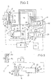
- Fig. 2 is associated with the internal combustion engine M, for example a diesel engine, a multi-field radiator or a radiator set 1 of a plurality of radiators, in the embodiment shown, a cooling area 1 a for the intake air or charge air, a cooling area 1 b for the cooling liquid of the internal combustion engine M, and a cooling area 1c for the hydraulic medium, and to which a common fan 2 is associated with a drive motor 3, which is controlled by the cooling control system S with respect to the optimum operating temperature of the engine M. 4, the power supply to the drive motor 3 is indicated.
- the drive motor 3 can be fed, for example, from the hydraulic system, or electrically via the generator G driven by the engine M, or directly or indirectly via the crankshaft of the internal combustion engine M.
- a pump distributor gearbox 5 flanged at the outputs of which a plurality of hydraulic pumps 6 are mounted, which are hydraulically connected via connecting lines or pressure hoses with various hydrostatic drive units 7, 8, 9, 10 for the basis Fig. 1 explained working and functional components of the machine are connected.
- a common return line 11 to a hydraulic medium reservoir 12, usually a large-volume metal container, on the example, valve components 13 may be attached.
- the reservoir 12 may be connected via a line 14 to the cooling area 1c.
- the return line 11 may also be connected to the cooling area 1c.
- a bypass 15 may be provided, in which a thermostatic valve 16 or controllable by the control device R valve 16 may be included for the hydraulic medium flow.
- the internal combustion engine M is mounted on a motor console 17, which is mounted on motor bearings 18 on abutments 19 of the chassis 32 of the machine F vibration isolation.
- the generator G which is for example driven (not shown) by the pump distributor gear 5, may be mounted on the engine console 17.
- At least one heating device 20 may be provided for the hydraulic circuit or all hydraulic circuits H of the hydraulic system, for example in the return line 11, or in or at the reservoir 12, or at another suitable location in the machine F.
- the heating device 20 will be described in US Pat Fig. 2 For example, operated by a controllable by the control device R controller 21 from the generator G electrically.
- the heating device 20 could use the cooling water and / or waste heat at least of the internal combustion engine M.
- a temperature sensor 22 for the operating temperature of the hydraulic medium is arranged and connected to the control device R.
- a temperature sensor 22 may also be located on or in the reservoir 12, or in or at the cooling area 1c.
- a preferably computerized main control CU of the machine F may also be connected to (or associated with) the control device R, and e.g. in real time or preparatory information i7 e.g. to the hydraulic load state of the selected hydrostatic drive unit 7 provide.
- the hydraulic medium operating temperature setting and regulating device R has a programming and / or setting section P at which, for example, the desired operating temperature of the hydraulic medium can be set and monitored, and, if appropriate, a selection device W, at which a hydraulic medium operating temperature of at least about 60 ° C, preferably even about 75 ° C, adjustable, to which the hydraulic medium after commissioning is to be brought as quickly as possible, and an operating temperature range in normal operation of at least about 60 ° C.
- preferably about 75 ° C to 80 ° C, or preferably even up to almost 90 ° C can be adjusted, within which the operating temperature of the hydraulic medium is to be maintained during normal operation of the machine during processing of the paving material, regardless of how the cooling control system S the Cooling at least the cooling liquid for the internal combustion engine M regulates.
- a circulation pump 29 may be used.
- the cooling areas 1 a, 1 b, 1 c commonly associated blower 2 in Fig. 1 is expediently provided in the air flow path from the fan 2 to the cooling area 1c for the hydraulic medium at least one shielding or deflecting device 30, with which the cooling power generated by the blower 2 can be regulated individually for the cooling area 1c, for example via an actuator 31, of the control device R is actuated, or else, not shown, by at least one thermostat or other temperature sensor in the hydraulic circuit.
- the shielding or deflecting device 30 could include flaps, fins, or other airflow controlling elements.
- the operating temperature of the hydraulic medium in the hydraulic circuit H is independent of the control intervention of the cooling control system S at least for the cooling liquid of the internal combustion engine M depending on hydraulic load situations in the hydraulic circuit, especially on the hydraulic pumps 6 and / or the hydrostatic drive units.
- Fig. 3 illustrates a detail variant in which the cooling area 1c for the hydraulic medium is structurally separated from the cooling areas 1a and 1b of the cooling device 1.
- the cooling area 1c is formed by a separate hydraulic medium cooler 24, for example, to the return line 11 and the connecting line 14 to the reservoir 12 is connected, and an independent fan 2a is associated with its own drive motor 3a and a separate drive power supply 4a.
- the fan 2a may be operated via the control device R, as shown, or is thermostatically controlled only or depending on the measurement result of a temperature sensor in the hydraulic circuit H.
- the drive motor 3a may be either a hydraulic motor or an electric motor or is (not shown) from the crankshaft driven by the internal combustion engine, for example via a switchable clutch.
- the radiator 24 may be placed in the cooling device K, or at a suitable position in the engine F.
- cooling fins 25 may be provided and another blower 26 may be provided with a drive motor 27, which is also controlled for example by the control device R to additionally cool the hydraulic medium in the reservoir 12 as needed.
- the heating device 20 is arranged on or in the reservoir 12 in order to achieve as quickly as possible, for example, the desired operating temperature of at least about 60 ° C or more, or to keep the desired operating temperature range of above 60 ° C reliably, the In addition to heat hydraulic medium.
- the diagram in Fig. 4 shows for a common hydraulic medium (hydraulic oil of specification HLP 46 according to DIN 51524, Part 2), the behavior of the applied on the vertical axis kinematic viscosity KV above the operating temperature T.
- the kinematic viscosity is at an operating temperature of about 60 ° C, only half of kinematic viscosity at an operating temperature of about 40 ° C and substantially less than one tenth of the viscosity at about 0 ° C. In an operating temperature range between 75 ° C and about 80 ° C, the viscosity is only about half the viscosity at 60 ° C.
- This viscosity behavior of the specified hydraulic medium (other common hydraulic media for machines for processing paving material show a similar behavior of the kinematic viscosity over the operating temperature) is in the machine F of FIGS. 1 to 3 , and also the machine F in Fig. 5 used to improve the energy efficiency of the internal combustion engine and fuel by adjusting the relatively high operating temperature of at least about 60 ° C and maintaining an operating temperature range above about 60 ° C to save, in which the hydraulic medium is cooled and / or heated independently of the engine cooling individually.
- Fig. 4 illustrates as a built-in material processing machine F a feeder used to load, for example, the paver of Fig. 1 with paving material in front of the road paver drives on the subgrade, intermittently supplied from trucks or continuously via a conveyor with the paving material, and the paver always enough paving material in the bunker 36 fills so that the paver can continuously produce a ceiling layer.
- a feeder used to load, for example, the paver of Fig. 1 with paving material in front of the road paver drives on the subgrade, intermittently supplied from trucks or continuously via a conveyor with the paving material, and the paver always enough paving material in the bunker 36 fills so that the paver can continuously produce a ceiling layer.
- the in Fig. 5 shown feeder has on its chassis 32, the chassis 33, such as a crawler undercarriage, with at least one drive 43, and a very large bunker 36.
- the feeder is self-propelled and contains, as the primary drive source, the liquid-cooled internal combustion engine M, eg a diesel engine, with the cooling device K at least for the coolant.
- a hydraulically operated transverse conveyor 48 may be arranged, from which an ascending hydraulically operated longitudinal conveyor 49 extends rearwardly upwards, which has a hydraulically adjustable discharge end 52.
- the conveying device 49 may have a further hydraulic device 50.
- the feeder as the installation material processing machine F includes, for example, hydrostatic drive units for the traction drives 43, the cross conveyor 48, not shown Bunkerverstellwandzylinder, the device 50 and the discharge end 51, for the internal combustion engine M drives corresponding hydraulic pumps in at least one hydraulic circuit.
- the cooling device K can according to Fig. 2 or Fig.
- ⁇ 3 be adapted to adjust the hydraulic medium in the hydraulic circuit, regardless of the cooling of the cooling liquid of the internal combustion engine M depending on hydraulic load situations and the ambient climate to a hydraulic medium operating temperature of at least about 60 ° C and in a hydraulic medium operating temperature range of about about 60 ° C, preferably between 75 ° C and 80 ° C, in order to optimize the response in the hydraulic circuit, to reduce the viscosity of the hydraulic medium, and to reduce the fuel consumption of the internal combustion engine, which drive the feeder more efficiently and the hydraulic working and functional components more efficiently can operate.
Landscapes
- Engineering & Computer Science (AREA)
- General Engineering & Computer Science (AREA)
- Civil Engineering (AREA)
- Mechanical Engineering (AREA)
- Combustion & Propulsion (AREA)
- Mining & Mineral Resources (AREA)
- Chemical & Material Sciences (AREA)
- Structural Engineering (AREA)
- Road Paving Machines (AREA)
- Preliminary Treatment Of Fibers (AREA)
- Control Of Position, Course, Altitude, Or Attitude Of Moving Bodies (AREA)
- Forklifts And Lifting Vehicles (AREA)
- Control Of Temperature (AREA)
- Fluid-Pressure Circuits (AREA)
- Cooling, Air Intake And Gas Exhaust, And Fuel Tank Arrangements In Propulsion Units (AREA)
Priority Applications (6)
| Application Number | Priority Date | Filing Date | Title |
|---|---|---|---|
| EP09008470.8A EP2282029B2 (fr) | 2009-06-29 | 2009-06-29 | Machine autoporteuse |
| DE502009000490T DE502009000490D1 (de) | 2009-06-29 | 2009-06-29 | Selbstfahrende Maschine |
| AT09008470T ATE503092T1 (de) | 2009-06-29 | 2009-06-29 | Selbstfahrende maschine |
| US12/821,925 US20100326067A1 (en) | 2009-06-29 | 2010-06-23 | Self-propelled machine |
| CN2010102202512A CN101936211B (zh) | 2009-06-29 | 2010-06-29 | 自驱动机械 |
| CN2010202491912U CN201794654U (zh) | 2009-06-29 | 2010-06-29 | 自驱动机械 |
Applications Claiming Priority (1)
| Application Number | Priority Date | Filing Date | Title |
|---|---|---|---|
| EP09008470.8A EP2282029B2 (fr) | 2009-06-29 | 2009-06-29 | Machine autoporteuse |
Publications (3)
| Publication Number | Publication Date |
|---|---|
| EP2282029A1 true EP2282029A1 (fr) | 2011-02-09 |
| EP2282029B1 EP2282029B1 (fr) | 2011-03-23 |
| EP2282029B2 EP2282029B2 (fr) | 2022-04-20 |
Family
ID=41697972
Family Applications (1)
| Application Number | Title | Priority Date | Filing Date |
|---|---|---|---|
| EP09008470.8A Active EP2282029B2 (fr) | 2009-06-29 | 2009-06-29 | Machine autoporteuse |
Country Status (5)
| Country | Link |
|---|---|
| US (1) | US20100326067A1 (fr) |
| EP (1) | EP2282029B2 (fr) |
| CN (2) | CN201794654U (fr) |
| AT (1) | ATE503092T1 (fr) |
| DE (1) | DE502009000490D1 (fr) |
Cited By (1)
| Publication number | Priority date | Publication date | Assignee | Title |
|---|---|---|---|---|
| DE102022111963A1 (de) | 2022-05-12 | 2023-11-16 | Dynapac Gmbh | Straßenbaumaschine |
Families Citing this family (13)
| Publication number | Priority date | Publication date | Assignee | Title |
|---|---|---|---|---|
| DE502009000490D1 (de) * | 2009-06-29 | 2011-05-05 | Joseph Voegele Ag | Selbstfahrende Maschine |
| PL2530273T3 (pl) * | 2011-06-01 | 2020-11-16 | Joseph Vögele AG | Maszyna budowlana z automatyczną regulacją prędkości obrotowej wentylatora |
| PL2578888T3 (pl) | 2011-10-07 | 2019-05-31 | Voegele Ag J | Maszyna budowlana z automatyczną regulacją prędkości obrotowej wentylatora |
| CN103233947A (zh) * | 2012-01-08 | 2013-08-07 | 钱荣华 | 一种冷却煤矿井下挖掘装载机及其它设备液压油的方法 |
| EP2672008B1 (fr) * | 2012-06-05 | 2018-01-10 | Joseph Vögele AG | Finisseur et procédé de montage d'un produit à mélanger avec un finisseur |
| JP6009480B2 (ja) * | 2014-03-06 | 2016-10-19 | 日立建機株式会社 | 建設機械の冷却ファン制御装置 |
| US9382675B2 (en) | 2014-06-16 | 2016-07-05 | Caterpillar Paving Products Inc. | Electric powered systems for paving machines |
| EP3205772B1 (fr) * | 2014-10-10 | 2020-09-23 | Sumitomo (S.H.I.) Construction Machinery Co., Ltd. | Dispositif de finition d'asphalte |
| CN104500716A (zh) * | 2014-12-30 | 2015-04-08 | 戴纳派克(中国)压实摊铺设备有限公司 | 齿轮油冷却系统及具有该齿轮油冷却系统的路面机械设备 |
| PL3075909T3 (pl) * | 2015-03-30 | 2018-02-28 | Joseph Vögele AG | Maszyna do budowy dróg z siecią do transmisji danych i zastosowanie części przewodu prądowego |
| PL3091125T3 (pl) | 2015-05-06 | 2017-12-29 | Joseph Vögele AG | Maszyna budowlana z urządzeniem podnoszącym dla procesu załadowczego i sposób przestawiania tylnej klapy |
| US10407869B2 (en) | 2015-05-26 | 2019-09-10 | Hitachi Construction Machinery Co., Ltd. | Construction machine provided with preheating unit and preheating method of construction machine |
| CN110725741A (zh) * | 2019-10-15 | 2020-01-24 | 吉林大学 | 一种并联组合的车辆双循环冷却系统 |
Citations (6)
| Publication number | Priority date | Publication date | Assignee | Title |
|---|---|---|---|---|
| US4785915A (en) | 1987-06-19 | 1988-11-22 | Westinghouse Electric Corp. | Elevator system monitoring cold oil |
| DE4439454A1 (de) | 1994-11-04 | 1996-05-09 | Man Takraf Foerdertechnik Gmbh | Schaltungsanordnung zum Vorwärmen von hydraulischen Kreisläufen |
| US6076488A (en) | 1997-03-17 | 2000-06-20 | Shin Caterpillar Mitsubishi Ltd. | Cooling device for a construction machine |
| WO2006046902A1 (fr) | 2004-10-27 | 2006-05-04 | Atlas Copco Rock Drills Ab | Appareil de forage et procede associe de commande d'un ventilateur |
| EP1741893A1 (fr) | 2005-07-06 | 2007-01-10 | Kobelco Construction Machinery Co., Ltd. | Système de commande pour ventilateur de refroidissement |
| EP1870576A1 (fr) | 2005-04-07 | 2007-12-26 | Hitachi Construction Machinery Co., Ltd. | Dispositif de refroidissement pour machine de construction |
Family Cites Families (22)
| Publication number | Priority date | Publication date | Assignee | Title |
|---|---|---|---|---|
| US2306379A (en) * | 1930-03-12 | 1942-12-29 | Oscar Christianson | Hydraulic power system |
| FR1295419A (fr) † | 1961-04-21 | 1962-06-08 | Richier Sa | Refroidisseur autorégulateur |
| GB988177A (en) * | 1962-03-09 | 1965-04-07 | Council Scient Ind Res | Improvements in hydraulic power transmission systems |
| DE2150710A1 (de) † | 1971-10-12 | 1973-04-19 | Gewerk Eisenhuette Westfalia | Einrichtung zur erwaermung der druckfluessigkeit, insbesondere schwer entflammbarer hydraulikfluessigkeiten, fuer hydraulische betriebsanlagen u.dgl |
| GB1396778A (en) † | 1972-03-28 | 1975-06-04 | Af Hydraulics | Fluid supply systems |
| DE2502792C2 (de) † | 1975-01-24 | 1986-01-02 | Robert Bosch Gmbh, 7000 Stuttgart | Vorrichtung zum Aufheizen der Hydraulikflüssigkeit eines hydrostatischen Kreislaufs |
| US4811561A (en) * | 1986-04-08 | 1989-03-14 | Vickers, Incorporated | Power transmission |
| DE19634503B4 (de) † | 1996-08-26 | 2006-01-19 | Joseph Voegele Ag | Straßenfertiger |
| US6378951B1 (en) † | 1997-07-23 | 2002-04-30 | Hydroacoustics, Inc. | Vibratory pavement breaker |
| SE509903C2 (sv) † | 1998-02-27 | 1999-03-22 | Volvo Wheel Loaders Ab | Kyl- och värmesystem |
| US6195989B1 (en) † | 1999-05-04 | 2001-03-06 | Caterpillar Inc. | Power control system for a machine |
| US6463891B2 (en) † | 1999-12-17 | 2002-10-15 | Caterpillar Inc. | Twin fan control system and method |
| US6354089B1 (en) † | 2000-03-08 | 2002-03-12 | Case Corporation | Apparatus and method for cooling multiple fluids on a work vehicle |
| US6314950B1 (en) * | 2000-12-01 | 2001-11-13 | Caterpillar Inc. | Intake air temperature control system |
| AU2002234067A1 (en) * | 2001-01-05 | 2002-07-16 | Ingersoll-Rand Company | Hydraulic valve system |
| US6772714B2 (en) * | 2001-08-16 | 2004-08-10 | Deere & Company | Electronic fan control |
| JP3952972B2 (ja) † | 2003-03-07 | 2007-08-01 | コベルコ建機株式会社 | 建設機械の冷却装置 |
| CA2501917A1 (fr) * | 2004-03-23 | 2005-09-23 | Hydra-Fab Fluid Power Inc. | Systeme de guidage et de refroidissement de la transmission d'un ventilateur electro-hydraulique pour un vehicule |
| DE102004038896A1 (de) † | 2004-08-11 | 2006-02-23 | Keller Grundbau Gmbh | Verfahren zur Fundamentsicherung sowie Bohr- und Mischwerkzeug |
| JP4741606B2 (ja) * | 2005-12-27 | 2011-08-03 | 日立建機株式会社 | 油圧作業機のポンプ制御装置、ポンプ制御方法、および建設機械 |
| DE202007005860U1 (de) † | 2007-04-21 | 2008-08-21 | Liebherr-Werk Bischofshofen Ges.M.B.H. | Kühleranlage |
| DE502009000490D1 (de) * | 2009-06-29 | 2011-05-05 | Joseph Voegele Ag | Selbstfahrende Maschine |
-
2009
- 2009-06-29 DE DE502009000490T patent/DE502009000490D1/de active Active
- 2009-06-29 AT AT09008470T patent/ATE503092T1/de active
- 2009-06-29 EP EP09008470.8A patent/EP2282029B2/fr active Active
-
2010
- 2010-06-23 US US12/821,925 patent/US20100326067A1/en not_active Abandoned
- 2010-06-29 CN CN2010202491912U patent/CN201794654U/zh not_active Expired - Lifetime
- 2010-06-29 CN CN2010102202512A patent/CN101936211B/zh active Active
Patent Citations (6)
| Publication number | Priority date | Publication date | Assignee | Title |
|---|---|---|---|---|
| US4785915A (en) | 1987-06-19 | 1988-11-22 | Westinghouse Electric Corp. | Elevator system monitoring cold oil |
| DE4439454A1 (de) | 1994-11-04 | 1996-05-09 | Man Takraf Foerdertechnik Gmbh | Schaltungsanordnung zum Vorwärmen von hydraulischen Kreisläufen |
| US6076488A (en) | 1997-03-17 | 2000-06-20 | Shin Caterpillar Mitsubishi Ltd. | Cooling device for a construction machine |
| WO2006046902A1 (fr) | 2004-10-27 | 2006-05-04 | Atlas Copco Rock Drills Ab | Appareil de forage et procede associe de commande d'un ventilateur |
| EP1870576A1 (fr) | 2005-04-07 | 2007-12-26 | Hitachi Construction Machinery Co., Ltd. | Dispositif de refroidissement pour machine de construction |
| EP1741893A1 (fr) | 2005-07-06 | 2007-01-10 | Kobelco Construction Machinery Co., Ltd. | Système de commande pour ventilateur de refroidissement |
Cited By (1)
| Publication number | Priority date | Publication date | Assignee | Title |
|---|---|---|---|---|
| DE102022111963A1 (de) | 2022-05-12 | 2023-11-16 | Dynapac Gmbh | Straßenbaumaschine |
Also Published As
| Publication number | Publication date |
|---|---|
| CN201794654U (zh) | 2011-04-13 |
| EP2282029B1 (fr) | 2011-03-23 |
| CN101936211B (zh) | 2013-03-13 |
| CN101936211A (zh) | 2011-01-05 |
| DE502009000490D1 (de) | 2011-05-05 |
| US20100326067A1 (en) | 2010-12-30 |
| ATE503092T1 (de) | 2011-04-15 |
| EP2282029B2 (fr) | 2022-04-20 |
Similar Documents
| Publication | Publication Date | Title |
|---|---|---|
| EP2282029B1 (fr) | Machine autoporteuse | |
| EP2256248B1 (fr) | Finisseuse de route et procédé | |
| EP2420621B1 (fr) | Finisseuse de route et procédé de fonctionnement d'une finisseuse de route | |
| DE4327261C1 (de) | Kühlmittelkreislauf | |
| DE69834891T2 (de) | Kühlungsanlage für die Brennkraftmaschine einer Lokomotive | |
| DE60025722T2 (de) | Baumaschine | |
| EP2333157A1 (fr) | Procédé de réglage de la puissance d'une finisseuse ou d'un chargeur et finisseuse ou chargeur | |
| DE3024209A1 (de) | Fluessigkeitskuehlung fuer verbrennungsmotoren | |
| DE102007005391A1 (de) | Kühleranordnung für einen Antriebsstrang eines Kraftfahrzeugs | |
| DE10334501A1 (de) | Fahrzeugverbrennungsmotorkühlsystem mit Wasserpumpe mit variabler Drehzahl | |
| DE102014008749A1 (de) | Bodenfräsmaschine mit kühlsystem, kühlsystem und verfahren zur kühlung einer bodenfräsmaschine | |
| EP2565334B1 (fr) | Engin doté d'un générateur refroidi par huile | |
| EP2821551B1 (fr) | Machine de construction dotée de structures de palier pouvant être chauffées | |
| DE102008011235A1 (de) | Temperaturregelanlage für Brennstoffzellen und Verfahren zur Temperaturregelung von Brennstoffzellen | |
| DE102006019086A1 (de) | Verfahren und Vorrichtung zur aktiven Öltemperierung bei Kraftfahrzeugen mit Verbrennungskraftmaschine | |
| DE19746330A1 (de) | Heizvorrichtung für ein Fahrzeug | |
| EP2333158B2 (fr) | Finisseur pour revêtements routiers | |
| DE102010051664A1 (de) | Arbeitsgerät | |
| DE102014012043A1 (de) | Verfahren zum Betreiben einer selbstfahrenden Straßenbaumaschine | |
| EP0931209B1 (fr) | Unite motrice a pompe hydraulique thermoregulee | |
| EP2774789A1 (fr) | Dispositif de chauffage pour machine de travail mobile | |
| EP3418451B1 (fr) | Appareil de travail doté d'un entraînement hydraulique pour travaux de génie civil | |
| DE19846364A1 (de) | Wärmeschichtspeicher und Verfahren zum Betreiben des Speichers | |
| DE102010051663A1 (de) | Arbeitsgerät | |
| DE102024115617A1 (de) | Straßenbaumaschine und Verfahren zur Nutzbarmachung oder Einrichtung einer Straßenbaumaschine |
Legal Events
| Date | Code | Title | Description |
|---|---|---|---|
| GRAP | Despatch of communication of intention to grant a patent |
Free format text: ORIGINAL CODE: EPIDOSNIGR1 |
|
| GRAS | Grant fee paid |
Free format text: ORIGINAL CODE: EPIDOSNIGR3 |
|
| PUAI | Public reference made under article 153(3) epc to a published international application that has entered the european phase |
Free format text: ORIGINAL CODE: 0009012 |
|
| 17P | Request for examination filed |
Effective date: 20100506 |
|
| AK | Designated contracting states |
Kind code of ref document: A1 Designated state(s): AT BE BG CH CY CZ DE DK EE ES FI FR GB GR HR HU IE IS IT LI LT LU LV MC MK MT NL NO PL PT RO SE SI SK TR |
|
| GRAA | (expected) grant |
Free format text: ORIGINAL CODE: 0009210 |
|
| AK | Designated contracting states |
Kind code of ref document: B1 Designated state(s): AT BE BG CH CY CZ DE DK EE ES FI FR GB GR HR HU IE IS IT LI LT LU LV MC MK MT NL NO PL PT RO SE SI SK TR |
|
| REG | Reference to a national code |
Ref country code: GB Ref legal event code: FG4D Free format text: NOT ENGLISH |
|
| RAP2 | Party data changed (patent owner data changed or rights of a patent transferred) |
Owner name: JOSEPH VOEGELE AG |
|
| REG | Reference to a national code |
Ref country code: CH Ref legal event code: EP |
|
| REG | Reference to a national code |
Ref country code: IE Ref legal event code: FG4D |
|
| REF | Corresponds to: |
Ref document number: 502009000490 Country of ref document: DE Date of ref document: 20110505 Kind code of ref document: P |
|
| REG | Reference to a national code |
Ref country code: DE Ref legal event code: R096 Ref document number: 502009000490 Country of ref document: DE Effective date: 20110505 |
|
| REG | Reference to a national code |
Ref country code: DE Ref legal event code: R081 Ref document number: 502009000490 Country of ref document: DE Owner name: JOSEPH VOEGELE AG, DE Free format text: FORMER OWNER: JOSEPH VOEGELE AG, 68163 MANNHEIM, DE Effective date: 20110329 |
|
| REG | Reference to a national code |
Ref country code: NL Ref legal event code: VDEP Effective date: 20110323 |
|
| PG25 | Lapsed in a contracting state [announced via postgrant information from national office to epo] |
Ref country code: SE Free format text: LAPSE BECAUSE OF FAILURE TO SUBMIT A TRANSLATION OF THE DESCRIPTION OR TO PAY THE FEE WITHIN THE PRESCRIBED TIME-LIMIT Effective date: 20110323 Ref country code: HR Free format text: LAPSE BECAUSE OF FAILURE TO SUBMIT A TRANSLATION OF THE DESCRIPTION OR TO PAY THE FEE WITHIN THE PRESCRIBED TIME-LIMIT Effective date: 20110323 Ref country code: LT Free format text: LAPSE BECAUSE OF FAILURE TO SUBMIT A TRANSLATION OF THE DESCRIPTION OR TO PAY THE FEE WITHIN THE PRESCRIBED TIME-LIMIT Effective date: 20110323 Ref country code: GR Free format text: LAPSE BECAUSE OF FAILURE TO SUBMIT A TRANSLATION OF THE DESCRIPTION OR TO PAY THE FEE WITHIN THE PRESCRIBED TIME-LIMIT Effective date: 20110624 Ref country code: LV Free format text: LAPSE BECAUSE OF FAILURE TO SUBMIT A TRANSLATION OF THE DESCRIPTION OR TO PAY THE FEE WITHIN THE PRESCRIBED TIME-LIMIT Effective date: 20110323 |
|
| LTIE | Lt: invalidation of european patent or patent extension |
Effective date: 20110323 |
|
| PG25 | Lapsed in a contracting state [announced via postgrant information from national office to epo] |
Ref country code: FI Free format text: LAPSE BECAUSE OF FAILURE TO SUBMIT A TRANSLATION OF THE DESCRIPTION OR TO PAY THE FEE WITHIN THE PRESCRIBED TIME-LIMIT Effective date: 20110323 Ref country code: NO Free format text: LAPSE BECAUSE OF FAILURE TO SUBMIT A TRANSLATION OF THE DESCRIPTION OR TO PAY THE FEE WITHIN THE PRESCRIBED TIME-LIMIT Effective date: 20110623 Ref country code: BG Free format text: LAPSE BECAUSE OF FAILURE TO SUBMIT A TRANSLATION OF THE DESCRIPTION OR TO PAY THE FEE WITHIN THE PRESCRIBED TIME-LIMIT Effective date: 20110623 Ref country code: SI Free format text: LAPSE BECAUSE OF FAILURE TO SUBMIT A TRANSLATION OF THE DESCRIPTION OR TO PAY THE FEE WITHIN THE PRESCRIBED TIME-LIMIT Effective date: 20110323 Ref country code: CY Free format text: LAPSE BECAUSE OF FAILURE TO SUBMIT A TRANSLATION OF THE DESCRIPTION OR TO PAY THE FEE WITHIN THE PRESCRIBED TIME-LIMIT Effective date: 20110323 |
|
| RAP2 | Party data changed (patent owner data changed or rights of a patent transferred) |
Owner name: JOSEPH VOEGELE AG |
|
| REG | Reference to a national code |
Ref country code: IE Ref legal event code: FD4D |
|
| PG25 | Lapsed in a contracting state [announced via postgrant information from national office to epo] |
Ref country code: PT Free format text: LAPSE BECAUSE OF FAILURE TO SUBMIT A TRANSLATION OF THE DESCRIPTION OR TO PAY THE FEE WITHIN THE PRESCRIBED TIME-LIMIT Effective date: 20110725 Ref country code: EE Free format text: LAPSE BECAUSE OF FAILURE TO SUBMIT A TRANSLATION OF THE DESCRIPTION OR TO PAY THE FEE WITHIN THE PRESCRIBED TIME-LIMIT Effective date: 20110323 |
|
| PG25 | Lapsed in a contracting state [announced via postgrant information from national office to epo] |
Ref country code: SK Free format text: LAPSE BECAUSE OF FAILURE TO SUBMIT A TRANSLATION OF THE DESCRIPTION OR TO PAY THE FEE WITHIN THE PRESCRIBED TIME-LIMIT Effective date: 20110323 Ref country code: ES Free format text: LAPSE BECAUSE OF FAILURE TO SUBMIT A TRANSLATION OF THE DESCRIPTION OR TO PAY THE FEE WITHIN THE PRESCRIBED TIME-LIMIT Effective date: 20110704 Ref country code: CZ Free format text: LAPSE BECAUSE OF FAILURE TO SUBMIT A TRANSLATION OF THE DESCRIPTION OR TO PAY THE FEE WITHIN THE PRESCRIBED TIME-LIMIT Effective date: 20110323 Ref country code: IS Free format text: LAPSE BECAUSE OF FAILURE TO SUBMIT A TRANSLATION OF THE DESCRIPTION OR TO PAY THE FEE WITHIN THE PRESCRIBED TIME-LIMIT Effective date: 20110723 |
|
| PLBI | Opposition filed |
Free format text: ORIGINAL CODE: 0009260 |
|
| PG25 | Lapsed in a contracting state [announced via postgrant information from national office to epo] |
Ref country code: NL Free format text: LAPSE BECAUSE OF FAILURE TO SUBMIT A TRANSLATION OF THE DESCRIPTION OR TO PAY THE FEE WITHIN THE PRESCRIBED TIME-LIMIT Effective date: 20110323 Ref country code: MT Free format text: LAPSE BECAUSE OF FAILURE TO SUBMIT A TRANSLATION OF THE DESCRIPTION OR TO PAY THE FEE WITHIN THE PRESCRIBED TIME-LIMIT Effective date: 20110323 |
|
| PLAB | Opposition data, opponent's data or that of the opponent's representative modified |
Free format text: ORIGINAL CODE: 0009299OPPO |
|
| BERE | Be: lapsed |
Owner name: JOSEPH VOGELE A.G. Effective date: 20110630 |
|
| 26 | Opposition filed |
Opponent name: BOMAC GMBH Effective date: 20111219 |
|
| PLAX | Notice of opposition and request to file observation + time limit sent |
Free format text: ORIGINAL CODE: EPIDOSNOBS2 |
|
| PG25 | Lapsed in a contracting state [announced via postgrant information from national office to epo] |
Ref country code: IE Free format text: LAPSE BECAUSE OF FAILURE TO SUBMIT A TRANSLATION OF THE DESCRIPTION OR TO PAY THE FEE WITHIN THE PRESCRIBED TIME-LIMIT Effective date: 20110323 |
|
| R26 | Opposition filed (corrected) |
Opponent name: BOMAG GMBH Effective date: 20111219 |
|
| PG25 | Lapsed in a contracting state [announced via postgrant information from national office to epo] |
Ref country code: PL Free format text: LAPSE BECAUSE OF FAILURE TO SUBMIT A TRANSLATION OF THE DESCRIPTION OR TO PAY THE FEE WITHIN THE PRESCRIBED TIME-LIMIT Effective date: 20110323 |
|
| REG | Reference to a national code |
Ref country code: DE Ref legal event code: R026 Ref document number: 502009000490 Country of ref document: DE Effective date: 20111219 |
|
| PG25 | Lapsed in a contracting state [announced via postgrant information from national office to epo] |
Ref country code: BE Free format text: LAPSE BECAUSE OF NON-PAYMENT OF DUE FEES Effective date: 20110630 |
|
| PLBB | Reply of patent proprietor to notice(s) of opposition received |
Free format text: ORIGINAL CODE: EPIDOSNOBS3 |
|
| PG25 | Lapsed in a contracting state [announced via postgrant information from national office to epo] |
Ref country code: MK Free format text: LAPSE BECAUSE OF FAILURE TO SUBMIT A TRANSLATION OF THE DESCRIPTION OR TO PAY THE FEE WITHIN THE PRESCRIBED TIME-LIMIT Effective date: 20110323 |
|
| PG25 | Lapsed in a contracting state [announced via postgrant information from national office to epo] |
Ref country code: MC Free format text: LAPSE BECAUSE OF NON-PAYMENT OF DUE FEES Effective date: 20110630 |
|
| PG25 | Lapsed in a contracting state [announced via postgrant information from national office to epo] |
Ref country code: LU Free format text: LAPSE BECAUSE OF NON-PAYMENT OF DUE FEES Effective date: 20110629 |
|
| PG25 | Lapsed in a contracting state [announced via postgrant information from national office to epo] |
Ref country code: TR Free format text: LAPSE BECAUSE OF FAILURE TO SUBMIT A TRANSLATION OF THE DESCRIPTION OR TO PAY THE FEE WITHIN THE PRESCRIBED TIME-LIMIT Effective date: 20110323 |
|
| PG25 | Lapsed in a contracting state [announced via postgrant information from national office to epo] |
Ref country code: HU Free format text: LAPSE BECAUSE OF FAILURE TO SUBMIT A TRANSLATION OF THE DESCRIPTION OR TO PAY THE FEE WITHIN THE PRESCRIBED TIME-LIMIT Effective date: 20110323 |
|
| REG | Reference to a national code |
Ref country code: CH Ref legal event code: PL |
|
| PG25 | Lapsed in a contracting state [announced via postgrant information from national office to epo] |
Ref country code: LI Free format text: LAPSE BECAUSE OF NON-PAYMENT OF DUE FEES Effective date: 20130630 Ref country code: CH Free format text: LAPSE BECAUSE OF NON-PAYMENT OF DUE FEES Effective date: 20130630 |
|
| PG25 | Lapsed in a contracting state [announced via postgrant information from national office to epo] |
Ref country code: RO Free format text: LAPSE BECAUSE OF FAILURE TO SUBMIT A TRANSLATION OF THE DESCRIPTION OR TO PAY THE FEE WITHIN THE PRESCRIBED TIME-LIMIT Effective date: 20110323 |
|
| REG | Reference to a national code |
Ref country code: AT Ref legal event code: MM01 Ref document number: 503092 Country of ref document: AT Kind code of ref document: T Effective date: 20140629 |
|
| PG25 | Lapsed in a contracting state [announced via postgrant information from national office to epo] |
Ref country code: AT Free format text: LAPSE BECAUSE OF NON-PAYMENT OF DUE FEES Effective date: 20140629 |
|
| APBM | Appeal reference recorded |
Free format text: ORIGINAL CODE: EPIDOSNREFNO |
|
| APBP | Date of receipt of notice of appeal recorded |
Free format text: ORIGINAL CODE: EPIDOSNNOA2O |
|
| APAH | Appeal reference modified |
Free format text: ORIGINAL CODE: EPIDOSCREFNO |
|
| APBQ | Date of receipt of statement of grounds of appeal recorded |
Free format text: ORIGINAL CODE: EPIDOSNNOA3O |
|
| REG | Reference to a national code |
Ref country code: FR Ref legal event code: PLFP Year of fee payment: 8 |
|
| REG | Reference to a national code |
Ref country code: FR Ref legal event code: PLFP Year of fee payment: 9 |
|
| REG | Reference to a national code |
Ref country code: FR Ref legal event code: PLFP Year of fee payment: 10 |
|
| APBU | Appeal procedure closed |
Free format text: ORIGINAL CODE: EPIDOSNNOA9O |
|
| PLAY | Examination report in opposition despatched + time limit |
Free format text: ORIGINAL CODE: EPIDOSNORE2 |
|
| PLBC | Reply to examination report in opposition received |
Free format text: ORIGINAL CODE: EPIDOSNORE3 |
|
| PLAB | Opposition data, opponent's data or that of the opponent's representative modified |
Free format text: ORIGINAL CODE: 0009299OPPO |
|
| R26 | Opposition filed (corrected) |
Opponent name: BOMAG GMBH Effective date: 20111219 |
|
| PUAH | Patent maintained in amended form |
Free format text: ORIGINAL CODE: 0009272 |
|
| STAA | Information on the status of an ep patent application or granted ep patent |
Free format text: STATUS: PATENT MAINTAINED AS AMENDED |
|
| 27A | Patent maintained in amended form |
Effective date: 20220420 |
|
| AK | Designated contracting states |
Kind code of ref document: B2 Designated state(s): AT BE BG CH CY CZ DE DK EE ES FI FR GB GR HR HU IE IS IT LI LT LU LV MC MK MT NL NO PL PT RO SE SI SK TR |
|
| REG | Reference to a national code |
Ref country code: DE Ref legal event code: R102 Ref document number: 502009000490 Country of ref document: DE |
|
| P01 | Opt-out of the competence of the unified patent court (upc) registered |
Effective date: 20230524 |
|
| PGFP | Annual fee paid to national office [announced via postgrant information from national office to epo] |
Ref country code: DE Payment date: 20250626 Year of fee payment: 17 |
|
| PGFP | Annual fee paid to national office [announced via postgrant information from national office to epo] |
Ref country code: GB Payment date: 20250621 Year of fee payment: 17 |
|
| PGFP | Annual fee paid to national office [announced via postgrant information from national office to epo] |
Ref country code: FR Payment date: 20250617 Year of fee payment: 17 |
|
| PGFP | Annual fee paid to national office [announced via postgrant information from national office to epo] |
Ref country code: IT Payment date: 20250627 Year of fee payment: 17 |