EP2282041B1 - Kraftstoffeinspritzsteuervorrichtung mit Vor- und Nach-Einspritzung - Google Patents
Kraftstoffeinspritzsteuervorrichtung mit Vor- und Nach-Einspritzung Download PDFInfo
- Publication number
- EP2282041B1 EP2282041B1 EP10168105.4A EP10168105A EP2282041B1 EP 2282041 B1 EP2282041 B1 EP 2282041B1 EP 10168105 A EP10168105 A EP 10168105A EP 2282041 B1 EP2282041 B1 EP 2282041B1
- Authority
- EP
- European Patent Office
- Prior art keywords
- fuel
- timing
- injection
- piston
- fuel injection
- Prior art date
- Legal status (The legal status is an assumption and is not a legal conclusion. Google has not performed a legal analysis and makes no representation as to the accuracy of the status listed.)
- Active
Links
Images


Classifications
-
- F—MECHANICAL ENGINEERING; LIGHTING; HEATING; WEAPONS; BLASTING
- F02—COMBUSTION ENGINES; HOT-GAS OR COMBUSTION-PRODUCT ENGINE PLANTS
- F02D—CONTROLLING COMBUSTION ENGINES
- F02D41/00—Electrical control of supply of combustible mixture or its constituents
- F02D41/30—Controlling fuel injection
- F02D41/38—Controlling fuel injection of the high pressure type
- F02D41/40—Controlling fuel injection of the high pressure type with means for controlling injection timing or duration
- F02D41/402—Multiple injections
-
- F—MECHANICAL ENGINEERING; LIGHTING; HEATING; WEAPONS; BLASTING
- F02—COMBUSTION ENGINES; HOT-GAS OR COMBUSTION-PRODUCT ENGINE PLANTS
- F02B—INTERNAL-COMBUSTION PISTON ENGINES; COMBUSTION ENGINES IN GENERAL
- F02B23/00—Other engines characterised by special shape or construction of combustion chambers to improve operation
- F02B23/02—Other engines characterised by special shape or construction of combustion chambers to improve operation with compression ignition
- F02B23/06—Other engines characterised by special shape or construction of combustion chambers to improve operation with compression ignition the combustion space being arranged in working piston
- F02B23/0645—Details related to the fuel injector or the fuel spray
- F02B23/0669—Details related to the fuel injector or the fuel spray having multiple fuel spray jets per injector nozzle
-
- F—MECHANICAL ENGINEERING; LIGHTING; HEATING; WEAPONS; BLASTING
- F02—COMBUSTION ENGINES; HOT-GAS OR COMBUSTION-PRODUCT ENGINE PLANTS
- F02D—CONTROLLING COMBUSTION ENGINES
- F02D41/00—Electrical control of supply of combustible mixture or its constituents
- F02D41/30—Controlling fuel injection
- F02D41/3011—Controlling fuel injection according to or using specific or several modes of combustion
- F02D41/3017—Controlling fuel injection according to or using specific or several modes of combustion characterised by the mode(s) being used
- F02D41/3035—Controlling fuel injection according to or using specific or several modes of combustion characterised by the mode(s) being used a mode being the premixed charge compression-ignition mode
-
- F—MECHANICAL ENGINEERING; LIGHTING; HEATING; WEAPONS; BLASTING
- F02—COMBUSTION ENGINES; HOT-GAS OR COMBUSTION-PRODUCT ENGINE PLANTS
- F02B—INTERNAL-COMBUSTION PISTON ENGINES; COMBUSTION ENGINES IN GENERAL
- F02B1/00—Engines characterised by fuel-air mixture compression
- F02B1/12—Engines characterised by fuel-air mixture compression with compression ignition
-
- F—MECHANICAL ENGINEERING; LIGHTING; HEATING; WEAPONS; BLASTING
- F02—COMBUSTION ENGINES; HOT-GAS OR COMBUSTION-PRODUCT ENGINE PLANTS
- F02B—INTERNAL-COMBUSTION PISTON ENGINES; COMBUSTION ENGINES IN GENERAL
- F02B2275/00—Other engines, components or details, not provided for in other groups of this subclass
- F02B2275/14—Direct injection into combustion chamber
-
- F—MECHANICAL ENGINEERING; LIGHTING; HEATING; WEAPONS; BLASTING
- F02—COMBUSTION ENGINES; HOT-GAS OR COMBUSTION-PRODUCT ENGINE PLANTS
- F02M—SUPPLYING COMBUSTION ENGINES IN GENERAL WITH COMBUSTIBLE MIXTURES OR CONSTITUENTS THEREOF
- F02M45/00—Fuel-injection apparatus characterised by having a cyclic delivery of specific time/pressure or time/quantity relationship
- F02M45/02—Fuel-injection apparatus characterised by having a cyclic delivery of specific time/pressure or time/quantity relationship with each cyclic delivery being separated into two or more parts
-
- Y—GENERAL TAGGING OF NEW TECHNOLOGICAL DEVELOPMENTS; GENERAL TAGGING OF CROSS-SECTIONAL TECHNOLOGIES SPANNING OVER SEVERAL SECTIONS OF THE IPC; TECHNICAL SUBJECTS COVERED BY FORMER USPC CROSS-REFERENCE ART COLLECTIONS [XRACs] AND DIGESTS
- Y02—TECHNOLOGIES OR APPLICATIONS FOR MITIGATION OR ADAPTATION AGAINST CLIMATE CHANGE
- Y02T—CLIMATE CHANGE MITIGATION TECHNOLOGIES RELATED TO TRANSPORTATION
- Y02T10/00—Road transport of goods or passengers
- Y02T10/10—Internal combustion engine [ICE] based vehicles
- Y02T10/12—Improving ICE efficiencies
-
- Y—GENERAL TAGGING OF NEW TECHNOLOGICAL DEVELOPMENTS; GENERAL TAGGING OF CROSS-SECTIONAL TECHNOLOGIES SPANNING OVER SEVERAL SECTIONS OF THE IPC; TECHNICAL SUBJECTS COVERED BY FORMER USPC CROSS-REFERENCE ART COLLECTIONS [XRACs] AND DIGESTS
- Y02—TECHNOLOGIES OR APPLICATIONS FOR MITIGATION OR ADAPTATION AGAINST CLIMATE CHANGE
- Y02T—CLIMATE CHANGE MITIGATION TECHNOLOGIES RELATED TO TRANSPORTATION
- Y02T10/00—Road transport of goods or passengers
- Y02T10/10—Internal combustion engine [ICE] based vehicles
- Y02T10/40—Engine management systems
Definitions
- the present invention relates to a fuel injection control apparatus, and more particularly to a fuel injection control apparatus for a premixed compression ignition diesel engine.
- Japanese Patent Application Publication No. 2002-180881 describes a combustion control apparatus that is used in a premixed diesel engine to improve the homogeneity of an air-fuel pre-mixture. Under predetermined engine operating conditions, this combustion control apparatus implements early injection in a predetermined period extending from the beginning of an intake stroke to the vicinity of top dead center of a compression stroke, favorably to a cylinder prior to 60° before compression top dead center, such that at least a part of the fuel is supplied, and the early injection fuel is injected after being divided into a plurality of portions.
- the amount of the fuel injected in each injection decreases, which is advantageous in terms of atomization and intermixing with air, and therefore a highly uniform lean air-fuel pre-mixture can be formed. As a result, reductions in amounts of black smoke and hydrocarbons (HC) generated are achieved.
- a fuel injection valve having a narrow cone angle an injection cone angle of 120° or less is used to ensure that all of the early injection fuel is supplied to the combustion chamber.
- a fuel injection control apparatus according to the preamble of claim 1 is known from EP 1 806 493 A1 . Further fuel injection control apparatuses are known from EP 1 701 027 A1 and US 2005/224606 A1 .
- the present invention has been designed to solve these problems, and an object thereof is to provide a fuel injection control apparatus that realizes premixed compression ignition combustion with low HC generation and high fuel efficiency.
- FIG. 1 shows a constructional diagram of a diesel engine incorporating a fuel injection control apparatus according to this embodiment.
- a diesel engine 1 includes cylinder block 4 having cylinders 3 in its interior.
- a cylinder head 5 is provided on the upper portion of cylinder block 4.
- a piston 6 is provided in cylinder 3 so as to be a reciprocatable and has a top surface 6a and inner surface 6b.
- One end of connecting rod 7 is connected to piston 6, and crankshaft 8 is connected to the other end of connecting rod 7.
- a combustion chamber 20 defined by top surface 6a and inner surface 6b of piston 6 is provided in piston 6.
- the combustion chamber 20 opens to cylinder 3.
- a fuel injection valve 2 for injecting a fuel (light oil) into cylinder 3 is provided in cylinder head 5.
- intake valve 11 for opening and closing intake port 9 and exhaust valve 12 for opening and closing exhaust port 10 are provided in cylinder head 5.
- An intake passage 13 is connected to intake port 9, and exhaust passage 14 is connected to exhaust port 10.
- the diesel engine 1 is further provided with ECU 15 serving as a control apparatus, and ECU 15 is electrically connected to both a drive control apparatus, not shown, of crankshaft 8 and fuel injection valve 2.
- intake valve 11 opens intake port 9 such that air flowing through intake passage 13 is sucked into cylinder 3.
- intake valve 11 closes intake port 9 and piston 6 rises in cylinder 3, whereby a compression stroke for compressing the sucked air begins.
- ECU 15 injects fuel that has been divided into a plurality of portions into cylinder 3 through fuel injection valve 2 at the appropriate timing as described below.
- the injected fuel intermixes with the air in cylinder 3 to form an air-fuel mixture, whereupon the air-fuel mixture is compressed by piston 6 such that the pressure and temperature of the air-fuel mixture increase.
- the temperature of the air-fuel mixture increases, the fuel auto-ignites, and as a result, combustion occurs in cylinder 3.
- ⁇ 150°, for example.
- the fuel is injected within a variation range of approximately ⁇ ⁇ 0.1 ⁇ (between the broken lines) rather than precisely at predetermined injection cone angle ⁇ (solid line).
- injection cone angle ⁇ is a value that can be determined unambiguously.
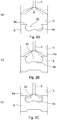
- a first timing As shown in Fig. 2A , if the fuel is injected from fuel injection valve 2 when the position of piston 6 within cylinder 3 is low, the fuel may not enter combustion chamber 20 directly but will adhere to the top surface 6a of piston 6 and the inner wall surface of cylinder 3.
- a first timing As shown in Fig. 2A , if piston 6 moves upward from the case shown in Fig. 2A , the fuel injected within the variation range of ⁇ 10% of predetermined injection cone angle ⁇ among the fuel injected through fuel injection valve 2 may begin to enter the combustion chamber 20 directly at a position of piston 6 depending on injection cone angle ⁇ and the size and shape of combustion chamber 20. This timing is defined as a first timing. As shown in Fig.
- the first timing corresponds to a crank angle position of 28° before compression top dead center (hereafter, referred to as "-28° ATDC”) and the second timing corresponds to a crank angle position of 18° before compression top dead center (hereafter, referred to as "-18° ATDC").
- fuel injection valve 2 injects a single portion of fuel immediately after -28° ATDC. Immediately after this injection, a second portion of fuel is injected as close as possible to the first injection without overlapping. Note that the amount of the fuel injected in the second injection takes a value obtained by subtracting the amount of the fuel injected in the first injection from the amount of fuel required to obtain the required torque, and this amount is larger than the amount of fuel injected in the first injection. As described above, at least a part of the fuel injected in these two injections (hereafter, referred to as "pre-injection") enters combustion chamber 20 directly (see Fig.
- fuel injection valve 2 injects a single portion of fuel immediately after -18° ATDC.
- the amount of the fuel injected at this time is approximately double the amount of fuel injected in the first injection at -28° ATDC timing and smaller than the amount of fuel injected in the second injection at -28° ATDC timing.
- post-injection all of the fuel injected in this injection enters combustion chamber 20 directly, and therefore this fuel does not adhere to the top surface 6a of piston 6 or the inner wall of cylinder 3.
- the amount of fuel injected in the respective injections decreases, and therefore the amount of fuel that adheres to the inner wall of cylinder 3 and top surface 6a of piston 6 in the pre-injection is reduced, thereby preventing the possibility of rapid combustion and a reduction in combustibility during the post-injection. Furthermore, by dividing the pre-injection into two injections, the amount of the fuel that adheres to the inner wall of cylinder 3 and top surface 6a of piston 6 is reduced even further. As a result, premixed compression ignition combustion with low HC generation and high fuel efficiency is realized.
- the pre-injection is divided into two injections, but the pre-injection is not limited to two injections and may be divided into three or more injections. However, the total amount of fuel injected in the second and subsequent injections must be greater than the amount of fuel injected in the first injection.
- the fuel is injected immediately after -28° ATDC and immediately after -18° ATDC, respectively, but the present invention is not limited to these timings. Instead, the fuel may be injected in two or more portions at an appropriate timing between -28° ATDC and -18° ATDC and then at an appropriate timing between -18° ATDC and compression top dead center. Note, however, that the fuel is preferably injected at timings that are as close as possible to -28° ATDC and -18° ATDC, respectively.
- -28° ATDC corresponds to the first timing and -18° ATDC corresponds to the second timing, but these numerical values are merely cited as examples.
- the first timing and second timing are determined in accordance with injection cone angle ⁇ and the size and shape of combustion chamber 20. Note that ⁇ 10% of injection cone angle ⁇ was set as the variation range of the fuel injected through fuel injection valve 2, but ⁇ 10% is also an example, and the variation range may be modified in accordance with the specifications of diesel engine 1.
- fuel injection valve 2 injects a single portion of the fuel immediately after -28° ATDC. Immediately after this injection, a second portion of the fuel is injected as close as possible to the first injection without overlapping. The amount of the fuel injected in the second injection takes a value obtained by subtracting the amount of the fuel injected in the first injection from the amount of the fuel required to obtain a required torque, and this amount is larger than the amount of the fuel injected in the first injection.
- fuel injection valve 2 injects a single portion of the fuel immediately after -18° ATDC. The amount of the fuel injected at this time is approximately double the amount of the fuel injected in the first injection at -28° ATDC timing and smaller than the amount of the fuel injected in the second injection.
Landscapes
- Engineering & Computer Science (AREA)
- Chemical & Material Sciences (AREA)
- Combustion & Propulsion (AREA)
- Mechanical Engineering (AREA)
- General Engineering & Computer Science (AREA)
- Electrical Control Of Air Or Fuel Supplied To Internal-Combustion Engine (AREA)
- Combustion Methods Of Internal-Combustion Engines (AREA)
- Fuel-Injection Apparatus (AREA)
Claims (3)
- Kraftstoffeinspritzsteuergerät (15) in einer vorgemischkompressionszündenden Dieselkraftmaschine (1) mit einem Kraftstoffeinspritzventil (2), das einen Kraftstoff in einer Mehrzahl von Portionen in einen Zylinder (3) einspritzt, wobei der Kraftstoffstrahl einen Konus eines vorbestimmten Winkels (θ) bildet, einem Kolben (6), der sich in dem Zylinder (3) hin- und herbewegt, und einer Verbrennungskammer (20), die durch eine obere Fläche (6a) und eine innere Fläche (6b) des Kolbens (6), die zu dem Zylinder (3) offen ist, definiert ist, und in dem Kolben (6) vorgesehen ist,
einem zweiten Zeitgebungsbestimmungsmittel zum Bestimmen, in einem Kompressionstakt, einer zweiten Zeitgebung, bei der der gesamte durch das Kraftstoffeinspritzventil (2) eingespritzte Kraftstoff die Brennkammer (20) betritt, in Übereinstimmung mit einer Position des Kolbens (6) in dem Zylinder (3) und einer Größe und Form der Brennkammer (20), wobei
das Kraftstoffeinspritzventil (20) die letzte Portion Kraftstoff von der zweiten Zeitgebung zu einem Punkt einspritzt, zu dem der Kolben den oberen Kompressionstotpunkt erreicht, dadurch gekennzeichnet, dass das Kraftstoffeinspritzgerät ferner aufweist:erste Zeitgebungsbestimmungsmittel zum Bestimmen, in einem Kompressionstakt, einer ersten Zeitgebung, zu der ein Teil des durch das Kraftstoffeinspritzventil (2) eingespritzten Kraftstoffs damit beginnt, die Brennkammer (20) direkt zu betreten, in Übereinstimmung mit einer Position des Kolbens (6) innerhalb des Zylinders (3) und einer Größe und Form der Brennkammer (20), wobeidas Kraftstoffeinspritzventil (2) eine erste Portion und zumindest eine zweite Portion des Kraftstoffs von der ersten Zeitgebung zu der zweiten Zeitgebung einspritzt, undwobei die erste Portion des Kraftstoffs kleiner als die zweite Portion des Kraftstoffs oder als eine Gesamtsumme der zweiten und nachfolgenden Portionen des von der ersten Zeitgebung zu der zweiten Zeitgebung eingespritzten Kraftstoffs ist. - Kraftstoffeinspritzsteuergerät (15) gemäß Anspruch 1, wobei die letzte Portion des Kraftstoffs kleiner als die zweite Portion des Kraftstoffs oder als die Gesamtsumme der zweiten und nachfolgenden Portionen des von der ersten Zeitgebung zu der zweiten Zeitgebung eingespritzten Kraftstoffs ist.
- Kraftstoffeinspritzsteuergerät (15) gemäß Anspruch 2, wobei die letzte Portion des Kraftstoffs größer als die erste Portion des Kraftstoffs ist.
Applications Claiming Priority (1)
| Application Number | Priority Date | Filing Date | Title |
|---|---|---|---|
| JP2009184243A JP5182250B2 (ja) | 2009-08-07 | 2009-08-07 | 燃料噴射制御装置 |
Publications (3)
| Publication Number | Publication Date |
|---|---|
| EP2282041A2 EP2282041A2 (de) | 2011-02-09 |
| EP2282041A3 EP2282041A3 (de) | 2015-05-20 |
| EP2282041B1 true EP2282041B1 (de) | 2018-06-06 |
Family
ID=43264733
Family Applications (1)
| Application Number | Title | Priority Date | Filing Date |
|---|---|---|---|
| EP10168105.4A Active EP2282041B1 (de) | 2009-08-07 | 2010-07-01 | Kraftstoffeinspritzsteuervorrichtung mit Vor- und Nach-Einspritzung |
Country Status (2)
| Country | Link |
|---|---|
| EP (1) | EP2282041B1 (de) |
| JP (1) | JP5182250B2 (de) |
Families Citing this family (3)
| Publication number | Priority date | Publication date | Assignee | Title |
|---|---|---|---|---|
| JP5333505B2 (ja) | 2011-04-12 | 2013-11-06 | 株式会社豊田自動織機 | 燃焼制御装置 |
| JP5902024B2 (ja) * | 2011-04-15 | 2016-04-13 | 株式会社日本自動車部品総合研究所 | 燃料噴射制御システム |
| JP2015218614A (ja) * | 2014-05-15 | 2015-12-07 | トヨタ自動車株式会社 | 内燃機関の燃料噴射制御装置 |
Family Cites Families (10)
| Publication number | Priority date | Publication date | Assignee | Title |
|---|---|---|---|---|
| JP2002180881A (ja) * | 2000-12-08 | 2002-06-26 | Mazda Motor Corp | ディーゼルエンジンの燃焼制御装置 |
| JP2003286879A (ja) * | 2002-03-27 | 2003-10-10 | Mazda Motor Corp | ディーゼルエンジンの燃焼制御装置 |
| JP4254361B2 (ja) * | 2003-06-12 | 2009-04-15 | トヨタ自動車株式会社 | 内燃機関の燃料噴射装置 |
| US7243862B2 (en) * | 2004-04-07 | 2007-07-17 | Delphi Technologies, Inc. | Apparatus and method for mode-switching fuel injector nozzle |
| JP3931900B2 (ja) * | 2004-10-06 | 2007-06-20 | いすゞ自動車株式会社 | ディーゼルエンジンの制御装置 |
| DE102005051740A1 (de) * | 2004-12-04 | 2006-06-08 | Daimlerchrysler Ag | Brennraum einer selbstzündenden Brennkraftmaschine |
| EP1701027B1 (de) * | 2005-03-11 | 2016-12-28 | Ford Global Technologies, Inc. | Methode für die Regeneration eines NOx-Speichers in einem Dieselmotors mittels Kompressionszündung einer teilweise homogenen Ladung |
| JP2006328999A (ja) * | 2005-05-24 | 2006-12-07 | Yanmar Co Ltd | 予混合圧縮自着火式内燃機関 |
| JP2009041532A (ja) * | 2007-08-10 | 2009-02-26 | Fuji Heavy Ind Ltd | ディーゼルエンジンの燃料噴射制御装置 |
| JP4911134B2 (ja) * | 2008-07-25 | 2012-04-04 | トヨタ自動車株式会社 | 内燃機関の燃料噴射装置 |
-
2009
- 2009-08-07 JP JP2009184243A patent/JP5182250B2/ja active Active
-
2010
- 2010-07-01 EP EP10168105.4A patent/EP2282041B1/de active Active
Non-Patent Citations (1)
| Title |
|---|
| None * |
Also Published As
| Publication number | Publication date |
|---|---|
| JP5182250B2 (ja) | 2013-04-17 |
| EP2282041A2 (de) | 2011-02-09 |
| EP2282041A3 (de) | 2015-05-20 |
| JP2011038417A (ja) | 2011-02-24 |
Similar Documents
| Publication | Publication Date | Title |
|---|---|---|
| CN100564828C (zh) | 内燃机 | |
| JP4106055B2 (ja) | 火花点火内燃機関を運転するための方法 | |
| US8800530B2 (en) | Stratified charge port injection engine and method | |
| US7021276B2 (en) | Control strategy for HCCI-CD combustion in a diesel engine using two fuel injection phases | |
| JP4007310B2 (ja) | 2種類の燃料を用いる予混合圧縮自着火運転可能な内燃機関 | |
| EP1574697A1 (de) | Methode und Vorrichtung für die Steuerung eines Kraftstoffeinspritzsystems mit einer Einspritzdüse im Saugrohr und einer Einspritzdüse im Zylinder | |
| US9115640B2 (en) | Internal combustion engine with a first and a second injecter | |
| CN106062336A (zh) | 低反应性压缩点火对置活塞发动机 | |
| US10087817B2 (en) | Reciprocating piston internal combustion engine having an ancillary chamber containing a piston, and method for operating the same | |
| CN100516475C (zh) | 给柴油发动机加注燃料的策略 | |
| CN115038860A (zh) | 用于操作机动车的、尤其是汽车的内燃机的方法 | |
| EP2511505B1 (de) | Verbrennungssteuerungsvorrichtung | |
| EP2282041A2 (de) | Kraftstoffeinspritzsteuervorrichtung mit Vor- und Nach-Einspritzung | |
| CN108026854B (zh) | 通过喷射温度以反应性控制来控制压燃式内燃机的燃烧的方法 | |
| US7404390B2 (en) | Method for operating an externally ignited internal combustion engine | |
| JP2006017082A (ja) | 内燃機関の制御装置 | |
| JP7411669B2 (ja) | 内燃機関のプレイグニッションを低減する方法 | |
| JP2011202624A (ja) | 燃料噴射制御装置 | |
| US11008970B2 (en) | Control device for engine | |
| US20170058816A1 (en) | Control apparatus of engine | |
| JP2006002719A (ja) | 内燃機関の制御装置 | |
| JP2006257999A (ja) | 内燃機関 | |
| JP2022076373A (ja) | 6ストローク内燃機関 | |
| CN113915037A (zh) | 一种具有双喷射系统的二冲程发动机 | |
| EP3322886A1 (de) | Verfahren zur steuerung der verbrennung eines kompressionsgezündeten verbrennungsmotors mit reaktivitätskontrolle durch die einspritztemperatur |
Legal Events
| Date | Code | Title | Description |
|---|---|---|---|
| PUAI | Public reference made under article 153(3) epc to a published international application that has entered the european phase |
Free format text: ORIGINAL CODE: 0009012 |
|
| 17P | Request for examination filed |
Effective date: 20100701 |
|
| AK | Designated contracting states |
Kind code of ref document: A2 Designated state(s): AL AT BE BG CH CY CZ DE DK EE ES FI FR GB GR HR HU IE IS IT LI LT LU LV MC MK MT NL NO PL PT RO SE SI SK SM TR |
|
| AX | Request for extension of the european patent |
Extension state: BA ME RS |
|
| PUAL | Search report despatched |
Free format text: ORIGINAL CODE: 0009013 |
|
| AK | Designated contracting states |
Kind code of ref document: A3 Designated state(s): AL AT BE BG CH CY CZ DE DK EE ES FI FR GB GR HR HU IE IS IT LI LT LU LV MC MK MT NL NO PL PT RO SE SI SK SM TR |
|
| AX | Request for extension of the european patent |
Extension state: BA ME RS |
|
| RIC1 | Information provided on ipc code assigned before grant |
Ipc: F02B 23/06 20060101ALI20150416BHEP Ipc: F02B 1/12 20060101ALN20150416BHEP Ipc: F02M 45/02 20060101ALN20150416BHEP Ipc: F02D 41/30 20060101ALI20150416BHEP Ipc: F02D 41/40 20060101AFI20150416BHEP |
|
| 17Q | First examination report despatched |
Effective date: 20160205 |
|
| GRAP | Despatch of communication of intention to grant a patent |
Free format text: ORIGINAL CODE: EPIDOSNIGR1 |
|
| RIC1 | Information provided on ipc code assigned before grant |
Ipc: F02B 1/12 20060101ALN20171127BHEP Ipc: F02D 41/40 20060101AFI20171127BHEP Ipc: F02D 41/30 20060101ALI20171127BHEP Ipc: F02B 23/06 20060101ALI20171127BHEP Ipc: F02M 45/02 20060101ALN20171127BHEP |
|
| RIC1 | Information provided on ipc code assigned before grant |
Ipc: F02B 23/06 20060101ALI20171207BHEP Ipc: F02D 41/40 20060101AFI20171207BHEP Ipc: F02M 45/02 20060101ALN20171207BHEP Ipc: F02B 1/12 20060101ALN20171207BHEP Ipc: F02D 41/30 20060101ALI20171207BHEP |
|
| INTG | Intention to grant announced |
Effective date: 20171218 |
|
| GRAS | Grant fee paid |
Free format text: ORIGINAL CODE: EPIDOSNIGR3 |
|
| GRAA | (expected) grant |
Free format text: ORIGINAL CODE: 0009210 |
|
| AK | Designated contracting states |
Kind code of ref document: B1 Designated state(s): AL AT BE BG CH CY CZ DE DK EE ES FI FR GB GR HR HU IE IS IT LI LT LU LV MC MK MT NL NO PL PT RO SE SI SK SM TR |
|
| REG | Reference to a national code |
Ref country code: GB Ref legal event code: FG4D |
|
| REG | Reference to a national code |
Ref country code: CH Ref legal event code: EP Ref country code: AT Ref legal event code: REF Ref document number: 1006360 Country of ref document: AT Kind code of ref document: T Effective date: 20180615 |
|
| REG | Reference to a national code |
Ref country code: IE Ref legal event code: FG4D |
|
| REG | Reference to a national code |
Ref country code: DE Ref legal event code: R096 Ref document number: 602010051072 Country of ref document: DE |
|
| REG | Reference to a national code |
Ref country code: FR Ref legal event code: PLFP Year of fee payment: 9 |
|
| REG | Reference to a national code |
Ref country code: NL Ref legal event code: MP Effective date: 20180606 |
|
| REG | Reference to a national code |
Ref country code: LT Ref legal event code: MG4D |
|
| PG25 | Lapsed in a contracting state [announced via postgrant information from national office to epo] |
Ref country code: ES Free format text: LAPSE BECAUSE OF FAILURE TO SUBMIT A TRANSLATION OF THE DESCRIPTION OR TO PAY THE FEE WITHIN THE PRESCRIBED TIME-LIMIT Effective date: 20180606 Ref country code: LT Free format text: LAPSE BECAUSE OF FAILURE TO SUBMIT A TRANSLATION OF THE DESCRIPTION OR TO PAY THE FEE WITHIN THE PRESCRIBED TIME-LIMIT Effective date: 20180606 Ref country code: CY Free format text: LAPSE BECAUSE OF FAILURE TO SUBMIT A TRANSLATION OF THE DESCRIPTION OR TO PAY THE FEE WITHIN THE PRESCRIBED TIME-LIMIT Effective date: 20180606 Ref country code: NO Free format text: LAPSE BECAUSE OF FAILURE TO SUBMIT A TRANSLATION OF THE DESCRIPTION OR TO PAY THE FEE WITHIN THE PRESCRIBED TIME-LIMIT Effective date: 20180906 Ref country code: FI Free format text: LAPSE BECAUSE OF FAILURE TO SUBMIT A TRANSLATION OF THE DESCRIPTION OR TO PAY THE FEE WITHIN THE PRESCRIBED TIME-LIMIT Effective date: 20180606 Ref country code: BG Free format text: LAPSE BECAUSE OF FAILURE TO SUBMIT A TRANSLATION OF THE DESCRIPTION OR TO PAY THE FEE WITHIN THE PRESCRIBED TIME-LIMIT Effective date: 20180906 Ref country code: SE Free format text: LAPSE BECAUSE OF FAILURE TO SUBMIT A TRANSLATION OF THE DESCRIPTION OR TO PAY THE FEE WITHIN THE PRESCRIBED TIME-LIMIT Effective date: 20180606 |
|
| PG25 | Lapsed in a contracting state [announced via postgrant information from national office to epo] |
Ref country code: GR Free format text: LAPSE BECAUSE OF FAILURE TO SUBMIT A TRANSLATION OF THE DESCRIPTION OR TO PAY THE FEE WITHIN THE PRESCRIBED TIME-LIMIT Effective date: 20180907 Ref country code: HR Free format text: LAPSE BECAUSE OF FAILURE TO SUBMIT A TRANSLATION OF THE DESCRIPTION OR TO PAY THE FEE WITHIN THE PRESCRIBED TIME-LIMIT Effective date: 20180606 Ref country code: LV Free format text: LAPSE BECAUSE OF FAILURE TO SUBMIT A TRANSLATION OF THE DESCRIPTION OR TO PAY THE FEE WITHIN THE PRESCRIBED TIME-LIMIT Effective date: 20180606 |
|
| REG | Reference to a national code |
Ref country code: AT Ref legal event code: MK05 Ref document number: 1006360 Country of ref document: AT Kind code of ref document: T Effective date: 20180606 |
|
| PG25 | Lapsed in a contracting state [announced via postgrant information from national office to epo] |
Ref country code: NL Free format text: LAPSE BECAUSE OF FAILURE TO SUBMIT A TRANSLATION OF THE DESCRIPTION OR TO PAY THE FEE WITHIN THE PRESCRIBED TIME-LIMIT Effective date: 20180606 |
|
| PG25 | Lapsed in a contracting state [announced via postgrant information from national office to epo] |
Ref country code: SK Free format text: LAPSE BECAUSE OF FAILURE TO SUBMIT A TRANSLATION OF THE DESCRIPTION OR TO PAY THE FEE WITHIN THE PRESCRIBED TIME-LIMIT Effective date: 20180606 Ref country code: RO Free format text: LAPSE BECAUSE OF FAILURE TO SUBMIT A TRANSLATION OF THE DESCRIPTION OR TO PAY THE FEE WITHIN THE PRESCRIBED TIME-LIMIT Effective date: 20180606 Ref country code: CZ Free format text: LAPSE BECAUSE OF FAILURE TO SUBMIT A TRANSLATION OF THE DESCRIPTION OR TO PAY THE FEE WITHIN THE PRESCRIBED TIME-LIMIT Effective date: 20180606 Ref country code: PL Free format text: LAPSE BECAUSE OF FAILURE TO SUBMIT A TRANSLATION OF THE DESCRIPTION OR TO PAY THE FEE WITHIN THE PRESCRIBED TIME-LIMIT Effective date: 20180606 Ref country code: IS Free format text: LAPSE BECAUSE OF FAILURE TO SUBMIT A TRANSLATION OF THE DESCRIPTION OR TO PAY THE FEE WITHIN THE PRESCRIBED TIME-LIMIT Effective date: 20181006 Ref country code: EE Free format text: LAPSE BECAUSE OF FAILURE TO SUBMIT A TRANSLATION OF THE DESCRIPTION OR TO PAY THE FEE WITHIN THE PRESCRIBED TIME-LIMIT Effective date: 20180606 Ref country code: AT Free format text: LAPSE BECAUSE OF FAILURE TO SUBMIT A TRANSLATION OF THE DESCRIPTION OR TO PAY THE FEE WITHIN THE PRESCRIBED TIME-LIMIT Effective date: 20180606 |
|
| PG25 | Lapsed in a contracting state [announced via postgrant information from national office to epo] |
Ref country code: SM Free format text: LAPSE BECAUSE OF FAILURE TO SUBMIT A TRANSLATION OF THE DESCRIPTION OR TO PAY THE FEE WITHIN THE PRESCRIBED TIME-LIMIT Effective date: 20180606 Ref country code: IT Free format text: LAPSE BECAUSE OF FAILURE TO SUBMIT A TRANSLATION OF THE DESCRIPTION OR TO PAY THE FEE WITHIN THE PRESCRIBED TIME-LIMIT Effective date: 20180606 |
|
| REG | Reference to a national code |
Ref country code: CH Ref legal event code: PL |
|
| REG | Reference to a national code |
Ref country code: DE Ref legal event code: R097 Ref document number: 602010051072 Country of ref document: DE |
|
| PG25 | Lapsed in a contracting state [announced via postgrant information from national office to epo] |
Ref country code: MC Free format text: LAPSE BECAUSE OF FAILURE TO SUBMIT A TRANSLATION OF THE DESCRIPTION OR TO PAY THE FEE WITHIN THE PRESCRIBED TIME-LIMIT Effective date: 20180606 Ref country code: LU Free format text: LAPSE BECAUSE OF NON-PAYMENT OF DUE FEES Effective date: 20180701 |
|
| REG | Reference to a national code |
Ref country code: BE Ref legal event code: MM Effective date: 20180731 |
|
| PLBE | No opposition filed within time limit |
Free format text: ORIGINAL CODE: 0009261 |
|
| STAA | Information on the status of an ep patent application or granted ep patent |
Free format text: STATUS: NO OPPOSITION FILED WITHIN TIME LIMIT |
|
| REG | Reference to a national code |
Ref country code: IE Ref legal event code: MM4A |
|
| PG25 | Lapsed in a contracting state [announced via postgrant information from national office to epo] |
Ref country code: CH Free format text: LAPSE BECAUSE OF NON-PAYMENT OF DUE FEES Effective date: 20180731 Ref country code: LI Free format text: LAPSE BECAUSE OF NON-PAYMENT OF DUE FEES Effective date: 20180731 Ref country code: IE Free format text: LAPSE BECAUSE OF NON-PAYMENT OF DUE FEES Effective date: 20180701 |
|
| 26N | No opposition filed |
Effective date: 20190307 |
|
| PG25 | Lapsed in a contracting state [announced via postgrant information from national office to epo] |
Ref country code: DK Free format text: LAPSE BECAUSE OF FAILURE TO SUBMIT A TRANSLATION OF THE DESCRIPTION OR TO PAY THE FEE WITHIN THE PRESCRIBED TIME-LIMIT Effective date: 20180606 Ref country code: BE Free format text: LAPSE BECAUSE OF NON-PAYMENT OF DUE FEES Effective date: 20180731 Ref country code: SI Free format text: LAPSE BECAUSE OF FAILURE TO SUBMIT A TRANSLATION OF THE DESCRIPTION OR TO PAY THE FEE WITHIN THE PRESCRIBED TIME-LIMIT Effective date: 20180606 |
|
| PG25 | Lapsed in a contracting state [announced via postgrant information from national office to epo] |
Ref country code: AL Free format text: LAPSE BECAUSE OF FAILURE TO SUBMIT A TRANSLATION OF THE DESCRIPTION OR TO PAY THE FEE WITHIN THE PRESCRIBED TIME-LIMIT Effective date: 20180606 |
|
| PG25 | Lapsed in a contracting state [announced via postgrant information from national office to epo] |
Ref country code: MT Free format text: LAPSE BECAUSE OF NON-PAYMENT OF DUE FEES Effective date: 20180701 |
|
| PG25 | Lapsed in a contracting state [announced via postgrant information from national office to epo] |
Ref country code: TR Free format text: LAPSE BECAUSE OF FAILURE TO SUBMIT A TRANSLATION OF THE DESCRIPTION OR TO PAY THE FEE WITHIN THE PRESCRIBED TIME-LIMIT Effective date: 20180606 |
|
| PG25 | Lapsed in a contracting state [announced via postgrant information from national office to epo] |
Ref country code: HU Free format text: LAPSE BECAUSE OF FAILURE TO SUBMIT A TRANSLATION OF THE DESCRIPTION OR TO PAY THE FEE WITHIN THE PRESCRIBED TIME-LIMIT; INVALID AB INITIO Effective date: 20100701 Ref country code: PT Free format text: LAPSE BECAUSE OF FAILURE TO SUBMIT A TRANSLATION OF THE DESCRIPTION OR TO PAY THE FEE WITHIN THE PRESCRIBED TIME-LIMIT Effective date: 20180606 |
|
| PG25 | Lapsed in a contracting state [announced via postgrant information from national office to epo] |
Ref country code: MK Free format text: LAPSE BECAUSE OF NON-PAYMENT OF DUE FEES Effective date: 20180606 |
|
| P01 | Opt-out of the competence of the unified patent court (upc) registered |
Effective date: 20230519 |
|
| PGFP | Annual fee paid to national office [announced via postgrant information from national office to epo] |
Ref country code: GB Payment date: 20250529 Year of fee payment: 16 |
|
| PGFP | Annual fee paid to national office [announced via postgrant information from national office to epo] |
Ref country code: FR Payment date: 20250610 Year of fee payment: 16 |
|
| PGFP | Annual fee paid to national office [announced via postgrant information from national office to epo] |
Ref country code: DE Payment date: 20250528 Year of fee payment: 16 |