EP2282052A2 - Verfahren und Vorrichtung zur Erhöhung des Auftriebs an einem Windturbinenblatt - Google Patents
Verfahren und Vorrichtung zur Erhöhung des Auftriebs an einem Windturbinenblatt Download PDFInfo
- Publication number
- EP2282052A2 EP2282052A2 EP10166088A EP10166088A EP2282052A2 EP 2282052 A2 EP2282052 A2 EP 2282052A2 EP 10166088 A EP10166088 A EP 10166088A EP 10166088 A EP10166088 A EP 10166088A EP 2282052 A2 EP2282052 A2 EP 2282052A2
- Authority
- EP
- European Patent Office
- Prior art keywords
- blade
- lift device
- sidewall
- wind turbine
- airfoil
- Prior art date
- Legal status (The legal status is an assumption and is not a legal conclusion. Google has not performed a legal analysis and makes no representation as to the accuracy of the status listed.)
- Withdrawn
Links
- 238000000034 method Methods 0.000 title description 23
- 230000001965 increasing effect Effects 0.000 title description 13
- 230000008878 coupling Effects 0.000 claims description 53
- 238000010168 coupling process Methods 0.000 claims description 53
- 238000005859 coupling reaction Methods 0.000 claims description 53
- 230000007246 mechanism Effects 0.000 claims description 17
- 239000011295 pitch Substances 0.000 description 17
- 230000004323 axial length Effects 0.000 description 12
- 238000000926 separation method Methods 0.000 description 6
- 230000003247 decreasing effect Effects 0.000 description 5
- 239000000463 material Substances 0.000 description 4
- 239000007787 solid Substances 0.000 description 4
- 238000010276 construction Methods 0.000 description 3
- 230000000694 effects Effects 0.000 description 3
- 239000002131 composite material Substances 0.000 description 2
- 230000003467 diminishing effect Effects 0.000 description 2
- 230000005611 electricity Effects 0.000 description 2
- 230000007613 environmental effect Effects 0.000 description 2
- 239000011521 glass Substances 0.000 description 2
- 230000001939 inductive effect Effects 0.000 description 2
- 239000002184 metal Substances 0.000 description 2
- 230000005012 migration Effects 0.000 description 2
- 238000013508 migration Methods 0.000 description 2
- 238000012806 monitoring device Methods 0.000 description 2
- 239000004033 plastic Substances 0.000 description 2
- 238000004088 simulation Methods 0.000 description 2
- 239000002023 wood Substances 0.000 description 2
- 230000007423 decrease Effects 0.000 description 1
- 230000003111 delayed effect Effects 0.000 description 1
- 230000003292 diminished effect Effects 0.000 description 1
- 230000006870 function Effects 0.000 description 1
- 230000004048 modification Effects 0.000 description 1
- 238000012986 modification Methods 0.000 description 1
- 230000002093 peripheral effect Effects 0.000 description 1
- 238000010248 power generation Methods 0.000 description 1
- 230000008569 process Effects 0.000 description 1
- 230000009467 reduction Effects 0.000 description 1
- 230000003068 static effect Effects 0.000 description 1
- 238000012546 transfer Methods 0.000 description 1
- 230000001131 transforming effect Effects 0.000 description 1
- 239000011800 void material Substances 0.000 description 1
Images


Classifications
-
- F—MECHANICAL ENGINEERING; LIGHTING; HEATING; WEAPONS; BLASTING
- F03—MACHINES OR ENGINES FOR LIQUIDS; WIND, SPRING, OR WEIGHT MOTORS; PRODUCING MECHANICAL POWER OR A REACTIVE PROPULSIVE THRUST, NOT OTHERWISE PROVIDED FOR
- F03D—WIND MOTORS
- F03D1/00—Wind motors with rotation axis substantially parallel to the air flow entering the rotor
- F03D1/06—Rotors
- F03D1/0608—Rotors characterised by their aerodynamic shape
-
- F—MECHANICAL ENGINEERING; LIGHTING; HEATING; WEAPONS; BLASTING
- F03—MACHINES OR ENGINES FOR LIQUIDS; WIND, SPRING, OR WEIGHT MOTORS; PRODUCING MECHANICAL POWER OR A REACTIVE PROPULSIVE THRUST, NOT OTHERWISE PROVIDED FOR
- F03D—WIND MOTORS
- F03D1/00—Wind motors with rotation axis substantially parallel to the air flow entering the rotor
- F03D1/06—Rotors
- F03D1/065—Rotors characterised by their construction elements
- F03D1/0675—Rotors characterised by their construction elements of the blades
-
- F—MECHANICAL ENGINEERING; LIGHTING; HEATING; WEAPONS; BLASTING
- F03—MACHINES OR ENGINES FOR LIQUIDS; WIND, SPRING, OR WEIGHT MOTORS; PRODUCING MECHANICAL POWER OR A REACTIVE PROPULSIVE THRUST, NOT OTHERWISE PROVIDED FOR
- F03D—WIND MOTORS
- F03D7/00—Controlling wind motors
- F03D7/02—Controlling wind motors the wind motors having rotation axis substantially parallel to the air flow entering the rotor
- F03D7/022—Adjusting aerodynamic properties of the blades
- F03D7/0232—Adjusting aerodynamic properties of the blades with flaps or slats
-
- F—MECHANICAL ENGINEERING; LIGHTING; HEATING; WEAPONS; BLASTING
- F05—INDEXING SCHEMES RELATING TO ENGINES OR PUMPS IN VARIOUS SUBCLASSES OF CLASSES F01-F04
- F05B—INDEXING SCHEME RELATING TO WIND, SPRING, WEIGHT, INERTIA OR LIKE MOTORS, TO MACHINES OR ENGINES FOR LIQUIDS COVERED BY SUBCLASSES F03B, F03D AND F03G
- F05B2240/00—Components
- F05B2240/20—Rotors
- F05B2240/202—Rotors with adjustable area of intercepted fluid
-
- F—MECHANICAL ENGINEERING; LIGHTING; HEATING; WEAPONS; BLASTING
- F05—INDEXING SCHEMES RELATING TO ENGINES OR PUMPS IN VARIOUS SUBCLASSES OF CLASSES F01-F04
- F05B—INDEXING SCHEME RELATING TO WIND, SPRING, WEIGHT, INERTIA OR LIKE MOTORS, TO MACHINES OR ENGINES FOR LIQUIDS COVERED BY SUBCLASSES F03B, F03D AND F03G
- F05B2240/00—Components
- F05B2240/20—Rotors
- F05B2240/30—Characteristics of rotor blades, i.e. of any element transforming dynamic fluid energy to or from rotational energy and being attached to a rotor
- F05B2240/301—Cross-section characteristics
-
- F—MECHANICAL ENGINEERING; LIGHTING; HEATING; WEAPONS; BLASTING
- F05—INDEXING SCHEMES RELATING TO ENGINES OR PUMPS IN VARIOUS SUBCLASSES OF CLASSES F01-F04
- F05B—INDEXING SCHEME RELATING TO WIND, SPRING, WEIGHT, INERTIA OR LIKE MOTORS, TO MACHINES OR ENGINES FOR LIQUIDS COVERED BY SUBCLASSES F03B, F03D AND F03G
- F05B2240/00—Components
- F05B2240/20—Rotors
- F05B2240/30—Characteristics of rotor blades, i.e. of any element transforming dynamic fluid energy to or from rotational energy and being attached to a rotor
- F05B2240/305—Flaps, slats or spoilers
- F05B2240/3052—Flaps, slats or spoilers adjustable
-
- F—MECHANICAL ENGINEERING; LIGHTING; HEATING; WEAPONS; BLASTING
- F05—INDEXING SCHEMES RELATING TO ENGINES OR PUMPS IN VARIOUS SUBCLASSES OF CLASSES F01-F04
- F05B—INDEXING SCHEME RELATING TO WIND, SPRING, WEIGHT, INERTIA OR LIKE MOTORS, TO MACHINES OR ENGINES FOR LIQUIDS COVERED BY SUBCLASSES F03B, F03D AND F03G
- F05B2240/00—Components
- F05B2240/20—Rotors
- F05B2240/30—Characteristics of rotor blades, i.e. of any element transforming dynamic fluid energy to or from rotational energy and being attached to a rotor
- F05B2240/31—Characteristics of rotor blades, i.e. of any element transforming dynamic fluid energy to or from rotational energy and being attached to a rotor of changeable form or shape
- F05B2240/313—Characteristics of rotor blades, i.e. of any element transforming dynamic fluid energy to or from rotational energy and being attached to a rotor of changeable form or shape with adjustable flow intercepting area
-
- Y—GENERAL TAGGING OF NEW TECHNOLOGICAL DEVELOPMENTS; GENERAL TAGGING OF CROSS-SECTIONAL TECHNOLOGIES SPANNING OVER SEVERAL SECTIONS OF THE IPC; TECHNICAL SUBJECTS COVERED BY FORMER USPC CROSS-REFERENCE ART COLLECTIONS [XRACs] AND DIGESTS
- Y02—TECHNOLOGIES OR APPLICATIONS FOR MITIGATION OR ADAPTATION AGAINST CLIMATE CHANGE
- Y02E—REDUCTION OF GREENHOUSE GAS [GHG] EMISSIONS, RELATED TO ENERGY GENERATION, TRANSMISSION OR DISTRIBUTION
- Y02E10/00—Energy generation through renewable energy sources
- Y02E10/70—Wind energy
- Y02E10/72—Wind turbines with rotation axis in wind direction
-
- Y—GENERAL TAGGING OF NEW TECHNOLOGICAL DEVELOPMENTS; GENERAL TAGGING OF CROSS-SECTIONAL TECHNOLOGIES SPANNING OVER SEVERAL SECTIONS OF THE IPC; TECHNICAL SUBJECTS COVERED BY FORMER USPC CROSS-REFERENCE ART COLLECTIONS [XRACs] AND DIGESTS
- Y10—TECHNICAL SUBJECTS COVERED BY FORMER USPC
- Y10T—TECHNICAL SUBJECTS COVERED BY FORMER US CLASSIFICATION
- Y10T29/00—Metal working
- Y10T29/49—Method of mechanical manufacture
- Y10T29/49316—Impeller making
- Y10T29/49336—Blade making
- Y10T29/49337—Composite blade
Definitions
- the subject matter described herein relates generally to wind turbines and, more particularly, to a method and apparatus for increasing lift on a wind turbine blade.
- Wind turbines convert the kinetic energy of wind into electrical energy.
- Wind turbines include one or more blades that rotate when oncoming wind strikes the blades. The flow of wind over the wind turbine blades generates lift and provides torque to generate power. As such, the amount of energy that a wind turbine can extract from the wind is directly related to the lift generated on the blades. The amount of lift generated on the blades depends on a number of factors. These factors include a speed of the wind, a lift coefficient of the blades, a planform area of the blades, and an air density of the wind.
- One technique that is used to increase lift, and thereby increase energy extracted by the wind turbine, is to increase the planform area of the blades.
- larger blades are more expensive, and may present structural issues in the wind turbine due to their larger weight.
- An additional technique for increasing lift is to pitch the blades such that an angle of attack is increased, thus increasing the lift coefficient.
- increasing the angle of attack above a critical angle of attack may result in air flow separation over the blades, thus stalling the blades. When stall occurs, lift generated by the blades decreases significantly and a large component of the torque is lost. Solutions that provide an ability to diminish or delay flow separation will allow the wind turbine blade to maximize lift.
- a lift device for a wind turbine blade includes a first sidewall and an opposing second sidewall.
- the lift device is configured to be coupled to the wind turbine blade along a leading edge of the wind turbine blade, and to generate lift when airflow is directed across at least one of the first sidewall and the second sidewall.
- the lift device may comprise a first airfoil.
- the first airfoil may be configured to be retractably coupled to the blade.
- the first airfoil may be offset from a root portion of the blade by a distance that is approximately 25% of the first length.
- the lift device may define an airflow channel between the airfoil and the leading edge of the blade.
- the blade may have a first length in an axial direction of the blade and the first airfoil may have a second length in the axial direction shorter than the first length.
- the profile of the first airfoil may substantially conform to a profile of a corresponding portion of the blade.
- the lift device may further comprise a second airfoil configured to be coupled to the leading edge of the blade and positioned axially between the first airfoil and a root portion of the blade.
- a wind turbine blade in another embodiment, includes a first sidewall and an opposing second sidewall, and the blade defines a leading edge and an opposing trailing edge.
- the blade includes a lift device configured to generate lift when airflow is directed across a surface of the lift device.
- the blade also includes a coupling mechanism that couples the lift device to the blade along the leading edge of the blade.
- the lift device may comprise a first airfoil.
- the first airfoil may be retractably coupled to the blade.
- the lift device may be operatively coupled to a control system, and the control system may be configured to pitch the lift device to a desired angle.
- the first airfoil may have a pitch angle that is different than a pitch angle of the blade.
- the blade may have a first length in an axial direction of the blade and the first airfoil may have a second length in the axial direction shorter than the first length.
- the profile of the first airfoil may substantially conform to a profile of a corresponding portion of the blade.
- the lift device may further comprise a second airfoil coupled to the leading edge of the blade and positioned axially between the first airfoil and a root portion of the blade.
- a method for assembling a wind turbine includes coupling at least one blade to the wind turbine.
- the blade includes a first sidewall and an opposing second sidewall, and the blade defines a leading edge and an opposing trailing edge.
- the method also includes coupling a lift device to the blade along the leading edge, such that the lift device is configured to generate lift when airflow is directed across a surface of the lift device.
- Coupling a lift device to the blade may comprise coupling a first airfoil to at least one of the first sidewall and the second sidewall.
- the method may further comprise forming the first airfoil such that the blade has a first length in an axial direction of the blade and the first airfoil has a second length in the axial direction shorter than the first length.
- the method may further comprise coupling a second airfoil to the blade along the leading edge, the second airfoil positioned axially between the first airfoil and a root portion of the blade.
- lift device for a wind turbine blade includes a first sidewall and an opposing second sidewall.
- the lift device is configured to be coupled to the wind turbine blade along a leading edge of the wind turbine blade, and to generate lift when airflow is directed across at least one of the first sidewall and the second sidewall.
- a wind turbine blade in another embodiment, includes a first sidewall and an opposing second sidewall, and the blade defines a leading edge and an opposing trailing edge.
- the blade includes a lift device configured to generate lift when airflow is directed across a surface of the lift device.
- the blade also includes a coupling mechanism that couples the lift device to the blade along the leading edge of the blade.
- a method for assembling a wind turbine includes coupling at least one blade to the wind turbine.
- the blade includes a first sidewall and an opposing second sidewall, and the blade defines a leading edge and an opposing trailing edge.
- the method also includes coupling a lift device to the blade along the leading edge, such that the lift device is configured to generate lift when airflow is directed across a surface of the lift device.
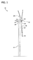
- At least one blade 18 is coupled to hub 16.
- three blades 18 are coupled to hub 16. More specifically, each blade 18 is coupled to hub 16 at a blade root portion 24. Each blade 18 extends outward from hub 16 from blade root portion 24 to a blade tip portion 26 along a blade axis 30. Blades 18 are rotatable about an axis of rotation 22 when wind strikes blades 18. In the exemplary embodiment, each blade 18 is oriented substantially perpendicularly to the ground. Each blade 18 rotates through substantially the same plane of rotation that is substantially parallel to a centerline axis 20 of tower 12.
- blades 18 are rotated about hub 16, and the kinetic energy of the wind is transformed into rotational energy by blades 18. More specifically, rotation of blades 18 rotates an axle that is coupled to a gearbox
- a pitch of each blade 18 is controlled individually by a control system 28.
- the blade pitch for all blades 18 may be controlled simultaneously by control system 28.
- control system 28 is shown as being centralized within nacelle 14, however, control system 28 may be a distributed system throughout wind turbine 10, within a wind farm, and/or at a remote control center.
- Control system 28 includes a processor configured to perform the methods and/or steps described herein. Further, many of the other components described herein include a processor.
- processor is not limited to integrated circuits referred to in the art as a computer, but broadly refers to a controller, a microcontroller, a microcomputer, a programmable logic controller (PLC), an application specific integrated circuit, and other programmable circuits, and these terms are used interchangeably herein. It should be understood that a processor and/or control system can also include memory, input channels, and/or output channels.
- memory may include, without limitation, a computer-readable medium, such as a random access memory (RAM), and a computer-readable non-volatile medium, such as flash memory.
- RAM random access memory
- flash memory Alternatively, a floppy disk, a compact disc-read only memory (CD-ROM), a magneto-optical disk (MOD), and/or a digital versatile disc (DVD) may also be used.
- input channels may include, without limitation, sensors and/or computer peripherals associated with an operator interface, such as a mouse and a keyboard.
- output channels may include, without limitation, a control device, an operator interface monitor and/or a display.
- Processors described herein process information transmitted from a plurality of electrical and electronic devices that may include, without limitation, sensors, actuators, compressors, control systems, and/or monitoring devices. Such processors may be physically located in, for example, a control system, a sensor, a monitoring device, a desktop computer, a laptop computer, a PLC cabinet, and/or a distributed control system (DCS) cabinet.
- RAM and storage devices store and transfer information and instructions to be executed by the processor(s). RAM and storage devices can also be used to store and provide temporary variables, static (i.e., non-changing) information and instructions, or other intermediate information to the processors during execution of instructions by the processor(s). Instructions that are executed may include, without limitation, flow control system control commands. The execution of sequences of instructions is not limited to any specific combination of hardware circuitry and software instructions.
- Figure 2 illustrates an exemplary blade 18 and an exemplary lift device 48 that may be used with wind turbine 10 (shown in Figure 1 ).
- Figure 3 illustrates lift device 48 in a retracted position with respect to blade 18.
- blade 18 includes a first sidewall 44 and an opposite second sidewall 46.
- First sidewall 44 is coupled to second sidewall 46 along a leading edge 40 and along an opposing trailing edge 42 to facilitate forming an airfoil shape.
- Leading edge 40 extends from blade root portion 24 (shown in Figure 1 ) to blade tip portion 26 (shown in Figure 1 ).
- a profile of leading edge 40 axially curves as leading edge 40 extends from blade root portion 24 to blade tip portion 26.
- an angle of attack of blade 18 near root portion 24 is different than an angle of attack of blade 18 near tip portion 26.
- the profile of blade 18 is substantially uniform as leading edge 40 extends from blade root portion 24 to blade tip portion 26.
- axial or “axially” refers to a direction along or substantially parallel to blade axis 30 (shown in Figure 1 ).
- radial or “radially” refers to a direction substantially perpendicular to blade axis 30.
- lift device 48 is coupled to leading edge 40 of blade 18 via a coupling mechanism 50. In an alternative embodiment, lift device 48 is coupled to blade 18 in any suitable location that allows lift device 48 to function as described herein.
- lift device 48 includes an airfoil 49 that has a first sidewall 54 and an opposite second sidewall 56 that define a leading edge 58 and an opposing trailing edge 60. In the exemplary embodiment, lift device 48 extends radially outward and downward from leading edge 40 of blade 18.
- Lift device 48 may be constructed using any suitable material including, without limitation, a suitable metal, wood, glass, plastic and/or composite material and combinations thereof.
- Lift device 48 may be formed from a single section or piece of material, or alternatively, first and second sidewalls 54 and 56 may be separate sections or pieces that are coupled together at leading edge 58 and trailing edge 60.
- lift device 48 is constructed with solid sidewalls 54 and 56 such that lift device 48 has a solid profile suitable for withstanding wind and weather conditions.
- a profile of leading edge 58 of lift device 48 substantially conforms to the profile of a corresponding portion of leading edge 40 of blade 18.
- the profile of lift device 48 axially curves as lift device 48 extends from blade root portion 24 towards blade tip portion 26.
- the profile of lift device 48 is substantially uniform as lift device 48 extends from blade root portion 24 towards blade tip portion 26.
- a pitch angle of lift device 48 is different than a pitch angle of blade 18, i.e. greater than or less than a pitch angle of blade 18.
- an angle of attack of lift device 48 is different than an angle of attack of blade 18, i.e. greater than or less than an angle of attack of lift device 48 relative to oncoming airflow.
- coupling mechanism 50 is retractable, such that lift device 48 may be extended or retracted with respect to leading edge 40 as desired.
- an airflow channel 52 is formed between second sidewall 56 of lift device 48 and leading edge 40 of blade 18.
- airflow channel 52 is substantially closed.
- coupling mechanism 50 is at least partially housed within blade 18.
- Coupling mechanism 50 may include any suitable mechanism or component to retract and extend lift device 48 including, without limitation, a hydraulic, pneumatic, and/or electric mechanism or component.
- Coupling mechanism 50 may be configured to tilt or pitch lift device 48 by rotation about a pivot point 68 in addition to retracting or extending lift device 48.
- coupling mechanism 50 is fixedly coupled to blade 18 and lift device 48 such that lift device 48 may not be retracted and/or pitched.
- a first partial flow of air 62 is directed across first sidewall 54 of lift device 48 and further across first sidewall 44 of blade 18.
- First partial flow of air 62 creates a low pressure zone above first sidewall 44 of blade 18 due to a camber of lift device 48 and a camber of blade 18.
- a second partial flow of air 64 is directed underneath lift device 48 and second sidewall 46 of blade 18.
- Second partial flow of air 64 creates a high pressure zone below second sidewall 46 of blade 18, thereby inducing lift to blade 18.
- a third partial flow of air 66 is directed into airflow channel 52.
- Third partial flow of air 66 facilitates delaying a separation of the first partial flow of air from first sidewall 44 of blade 18.
- the extension of lift device 48 facilitates diminishing and/or delaying stall in blade 18.
- the angle of attack of blade 18 may increase due to pitching of blade 18, due to rotation of blade 18 about axis of rotation 22 (shown in Figure 1 ), or due to changes in wind direction. As angle of attack of blade 18 increases, more airflow is directed through airflow channel 52 and separation of the first partial airflow from first sidewall 44 of blade 18 is reduced. As such, by operation of lift device 48, stall conditions can be diminished and/or delayed.
- lift device 48 may be retracted by coupling mechanism 50 to reduce drag on blade 18.
- airflow channel 52 is substantially closed such that third partial flow of air 66 is prevented from flowing between second sidewall 56 of lift device 48 and leading edge 40 of blade 18.
- leading edge 40 of blade 18 may be constructed with an opening or void 70 that substantially conforms to dimensions of lift device 48.
- lift device 48 may be retracted into opening 70 such that second sidewall 56 of lift device 48 is housed within blade 18, and first sidewall 54 of lift device 48 is substantially flush with an outer surface of first sidewall 44 of blade 18.
- blade 18 aerodynamically performs substantially the same as a blade that does not include lift device 48.
- control system 28 (shown in Figure 1 ) is operatively coupled to lift device 48 and to coupling mechanism 50.
- Control system 28 includes one or more sensors that measure environmental conditions, such as a wind speed, a speed of rotation of blades 18, and/or a direction of wind. The sensors provide feedback of the measured environmental conditions to control system 28. Based on the feedback from the sensors, control system 28 pitches, retracts, and/or extends lift device 48 as needed to optimize lift and minimize an amount of drag generated by lift device 48.
- lift device 48 is extended during low wind speeds, until a cut-out speed is reached at higher wind speeds. After the cut-out speed is reached, lift device 48 is retracted by coupling mechanism 50 and control system 28 to prevent damage to wind turbine 10 and to reduce drag and loading on blade 18.
- Lift device 48 facilitates reducing a separation of airflow from blade 18 as the angle of attack increases. As such, blade 18 may operate at a higher angle of attack than otherwise possible without lift device 48. In other words, blade 18 with lift device 48 has a higher critical angle of attack than a wind turbine blade without lift device 48. Simulations indicate that a lift device 48 may facilitate increasing the critical angle of attack of a blade by more than 40% at low wind speeds. Lift induced to blade 18 is directly proportional to the angle of attack up to the critical angle of attack. As such, lift device 48 induces higher lift to blade 18, thereby increasing the torque and electrical power generated by blade 18.
- a portion of lift device 48 substantially seals a portion of airflow channel 52 with coupling mechanism 50 in the extended position.
- air does not flow through airflow channel 52, but rather air is directed along first sidewall 44 and second sidewall 46 of blade 18, along first sidewall 54 of lift device 48, and underneath lift device 48.
- Aerodynamic properties of lift device 48 and blade 18 may be modified to achieve desired results.
- the pitch angle of lift device 48 may be increased or decreased with respect to blade 18 to achieve different airflow properties.
- a shape, a size, a camber, and/or construction of lift device 48 may be modified as desired to achieve desired aerodynamic properties.
- a distance that lift device 48 is extendable by coupling mechanism 50 may be modified, thus altering the dimensions and aerodynamic effect of airflow channel 52.
- Figure 4 illustrates a section of blade 18 and a secondary lift device 100 suitable for use with wind turbine 10 (shown in Figure 1 ).
- Figure 5 illustrates secondary lift device 100 in a retracted position with respect to blade 18.
- Blade 18 is described with reference to Figures 1 , 2 , and 3 , and components are identified with similar reference numerals in Figure 4 .
- blade 18 includes first sidewall 44 and second sidewall 46, leading edge 40, and trailing edge 42.
- Secondary lift device 100 is coupled to blade 18.
- secondary lift device 100 is coupled to blade 18 with an axially inner or first coupling member 102 and an axially outer or second coupling member 104.
- Secondary lift device 100 may be used independently, or in combination with lift device 48 (shown in Figure 2 ).
- lift device 48 is used in combination with secondary lift device 100.
- secondary lift device 100 includes a first sidewall 106 and an opposite second sidewall 108 that define a leading edge 110 and an opposing trailing edge 112 to facilitate forming an airfoil shape.
- first sidewall 106 and/or second sidewall 108 are cambered.
- secondary lift device 100 includes an airfoil 101.
- An axially inner end 103 of secondary lift device 100 is coupled to inner coupling member 102, and an axially outer end 105 of secondary lift device 100 is coupled to outer coupling member 104 to facilitate producing a desired aerodynamic effect.
- secondary lift device 100 is coupled to blade 18 such that a secondary airflow channel 130 is created between leading edge 40 of blade 18 and a trailing edge 112 of secondary lift device 100.
- a portion of secondary lift device 100 such as coupling members 102 and/or 104, substantially seals a portion of secondary airflow channel 130.
- at least a portion of air does not flow through secondary airflow channel 130, but rather at least a portion of air is directed along first sidewall 106 of secondary lift device 100 and along first sidewall 44 and second sidewall 46 of blade 18, and underneath secondary lift device 100, as more fully described below.
- Secondary lift device 100 may be constructed using any suitable material including, without limitation, a suitable metal, wood, glass, plastic and/or composite material and combinations thereof. Secondary lift device 100 may be formed from a single section or piece of material, or alternatively, first and second sidewalls 106 and 108 may be separate sections or pieces that are coupled together at leading edge 110 and trailing edge 112. In the exemplary embodiment, secondary lift device 100 is constructed with solid sidewalls 106 and 108 such that secondary lift device 100 has a solid profile suitable for withstanding wind and weather conditions.
- inner coupling member 102 includes a first sidewall 114 and an opposite second sidewall 116 that define a leading edge 122 and an opposing trailing edge 124.
- Outer coupling member 104 includes a first sidewall 118 and an opposite second sidewall 120 that define a leading edge 126 and an opposing trailing edge 128.
- inner and outer coupling members 102 and 104 are coupled to blade 18 along leading edge 40, such that inner and outer coupling members 102 and 104 substantially conform to respective portions of leading edge 40.
- secondary lift device 100 is coupled to blade 18 using inner and outer coupling members 102 and 104 along leading edge 40 at or near blade root portion 24.
- secondary lift device 100 is immovably or fixedly coupled to blade 18 via inner and outer coupling members 102 and 104.
- secondary lift device 100 is movably, such as pivotally and/or retractably coupled to blade 18 via inner and outer coupling members 102 and 104 such that secondary lift device 100 and/or inner and outer coupling members 102 and 104 may pivot about a pivot point 140 or be retracted into blade 18, as desired.
- secondary airflow channel 130 is substantially closed such that third partial flow of air 136 is prevented from flowing between second sidewall 108 of secondary lift device 100 and leading edge 40 of blade 18.
- secondary lift device 100 is substantially flush with leading edge 40 of blade 18.
- at least a portion 142 of inner and outer coupling members 102 and 104 retract into blade 18 when secondary lift device 100 is fully retracted.
- a first partial flow of air 132 is directed across first sidewall 106 of secondary lift device 100 and further across first sidewall 44 of blade 18.
- First partial flow of air 132 creates a low pressure zone above first sidewall 44 due to a camber of secondary lift device 100 and a camber of blade 18.
- a second partial flow of air 134 is directed across second sidewall 108 of secondary lift device 100 and further across second sidewall 46 of blade 18.
- Second partial flow of air 134 creates a high pressure zone below second sidewall 46 of blade 18, thereby inducing lift to blade 18.
- a third partial flow of air 136 is directed across second sidewall 108 of secondary lift device 100, into secondary airflow channel 130, and across first sidewall 44 of blade 18.
- Third partial flow of air 136 facilitates delaying a separation of first partial flow of air 132 from first sidewall 44 of blade 18.
- secondary lift device 100 facilitates diminishing and/or delaying stall in blade 18.
- a fourth partial flow of air 138 is directed across first sidewall 114 and/or second sidewall 118 of inner and outer coupling members 102 and 104 and further across first sidewall 44 of blade 18.
- a fifth partial flow of air 139 does not contact secondary lift device 100, but rather is directed across first sidewall 44 and/or second sidewall 46 of blade 18. Due to a camber of inner coupling member 102 and outer coupling member 104, one or more vortices of air flow are created within fourth partial flow of air 138 that flow across first sidewall 44 of blade 18 on either side of third partial flow of air 136. These vortices facilitate replenishing a boundary layer of air flow across first sidewall 44 of blade 18.
- the vortices interrupt a natural spanwise, or radially outward, migration of weak boundary layer air flow emanating from blade root portion 24.
- an increase in mixing energy that is created by secondary lift device 100 coupled between inner coupling member 102 and outer coupling member 104 blocks the spanwise migration of weak boundary layer air flow and improves a two-dimensional air flow pattern of a larger portion of blade 18.
- secondary lift device 100 and inner coupling member 102 and outer coupling member 104 facilitate overcoming poor aerodynamic performance near blade root portion 24 and facilitate increasing lift induced to blade root portion 24, thus enabling a more axially uniform flow of air from blade tip portion 26 to hub 16.
- Aerodynamic properties of secondary lift device 100 may be modified to achieve desired results. For example, a pitch angle of secondary lift device 100 may be increased or decreased with respect to blade 18 to achieve different airflow properties. Additionally, a shape, a size, a camber, and/or construction of secondary lift device 100 may be modified as desired to achieve desired aerodynamic properties. Moreover, a distance that secondary lift device 100 is extendable by inner and outer coupling members 102 and 104 may be modified, thus altering dimensions and aerodynamic effect of secondary airflow channel 130.
- existing wind turbine blades may be retrofitted with lift device 48 and/or secondary lift device 100 without a need for substantial blade modification. As such, traditional wind turbine blades may still be used while achieving improved aerodynamic performance.
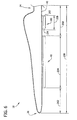
- Figure 6 illustrates a perspective view of an exemplary blade 18, an exemplary lift device 48, and an exemplary secondary lift device 100 that may be used with wind turbine 10 (shown in Figure 1 ).
- lift device 48 does not extend completely along leading edge 40 of blade 18 from blade root portion 24 to blade tip portion 26. Rather, lift device 48 is offset by a first predefined offset distance 200 from blade root portion 24, extends along leading edge 40 of blade 18, and terminates at a second predefined offset distance 202 from blade tip portion 26.
- lift device 48 has an axial length 204 that is shorter than an axial length 206 of blade 18.
- lift device 48 is offset from blade root portion 24 by first predefined offset distance 200 that is approximately 25% of axial length 206 of blade 18, and extends to second predefined offset distance 202 of approximately 25% of axial length 206 of blade 18 from blade tip portion 26.
- axial length 204 of lift device 48 is approximately 50% of axial length 206 of blade 18.
- first predefined offset distance 200 and/or second predefined offset distance 202 is less than or greater than 25% of axial length 206 of blade 18, but greater than 0%.
- first predefined offset distance 200 and second predefined offset distance 202 are both approximately 0%, such that lift device 48 extends substantially the full axial length 206 of blade 18 from root portion 24 to tip portion 26.
- blade 18 includes lift device 48 and secondary lift device 100.
- an axial length 208 of secondary lift device 100 is less than axial length 206 of blade 18. More specifically, in the exemplary embodiment, axial length 208 of secondary lift device 100 is less than axial length 204 of lift device 48.
- secondary lift device 100 is coupled to blade 18, via inner and outer coupling members 102 and 104, along leading edge 40 axially between blade root portion 24 and lift device 48.
- the above-described embodiments facilitate providing an efficient and cost-effective increase in wind turbine power generation. More power may be captured from a given wind speed due to the ability of the blades to utilize a higher angle of attack and a higher lift coefficient. Simulation data indicates that lift device 48 and secondary lift device 100 may facilitate increasing the critical angle of attack by more than 40%.
- the lift devices described herein facilitate a reduction in size of wind turbine blades while still generating substantially the same power rating as larger conventional blades. This facilitates decreasing the weight and loading of a wind turbine and also facilitates decreasing the cost of the overall wind turbine system.
- the above described embodiments also facilitate decreasing the pitch frequency of wind turbine blades because of the higher power capture capability of the lift device.
- the lift devices may be retracted during high wind speed events to facilitate protecting the blades and wind turbine components.
- Exemplary embodiments of a wind turbine, a high lift device, and a method for increasing lift induced to wind turbine blades are described above in detail.
- the turbine, device, and method are not limited to the specific embodiments described herein, but rather, components of the turbine, device and/or steps of the method may be utilized independently and separately from other components and/or steps described herein.
- the device may also be used in combination with other high lift systems and methods, and is not limited to practice with only the wind turbine and method as described herein. Rather, the exemplary embodiment can be implemented and utilized in connection with many other wind turbine applications.
Landscapes
- Engineering & Computer Science (AREA)
- Life Sciences & Earth Sciences (AREA)
- Sustainable Development (AREA)
- Sustainable Energy (AREA)
- Chemical & Material Sciences (AREA)
- Combustion & Propulsion (AREA)
- Mechanical Engineering (AREA)
- General Engineering & Computer Science (AREA)
- Physics & Mathematics (AREA)
- Fluid Mechanics (AREA)
- Wind Motors (AREA)
Applications Claiming Priority (1)
| Application Number | Priority Date | Filing Date | Title |
|---|---|---|---|
| US12/494,895 US8011886B2 (en) | 2009-06-30 | 2009-06-30 | Method and apparatus for increasing lift on wind turbine blade |
Publications (2)
| Publication Number | Publication Date |
|---|---|
| EP2282052A2 true EP2282052A2 (de) | 2011-02-09 |
| EP2282052A3 EP2282052A3 (de) | 2016-08-24 |
Family
ID=42231285
Family Applications (1)
| Application Number | Title | Priority Date | Filing Date |
|---|---|---|---|
| EP10166088.4A Withdrawn EP2282052A3 (de) | 2009-06-30 | 2010-06-16 | Verfahren und Vorrichtung zur Erhöhung des Auftriebs an einem Windturbinenblatt |
Country Status (2)
| Country | Link |
|---|---|
| US (1) | US8011886B2 (de) |
| EP (1) | EP2282052A3 (de) |
Cited By (3)
| Publication number | Priority date | Publication date | Assignee | Title |
|---|---|---|---|---|
| CN102650262A (zh) * | 2012-04-24 | 2012-08-29 | 李�杰 | 风叶失速可控制的垂直轴风力发电机 |
| EP2664791A2 (de) | 2012-05-18 | 2013-11-20 | Manuel Torres Martinez | Windturbinenschaufel mit veränderlicher Geometrie mit passiver Steuerung |
| US10352294B2 (en) | 2010-04-27 | 2019-07-16 | Lm Wp Patent Holding A/S | Wind turbine provided with a slat assembly |
Families Citing this family (27)
| Publication number | Priority date | Publication date | Assignee | Title |
|---|---|---|---|---|
| US8303250B2 (en) * | 2009-12-30 | 2012-11-06 | General Electric Company | Method and apparatus for increasing lift on wind turbine blade |
| US20110255972A1 (en) * | 2010-04-09 | 2011-10-20 | Gift Technologies, Llc | Multi-element wind turbine airfoils and wind turbines incorporating the same |
| US8011887B2 (en) * | 2010-07-21 | 2011-09-06 | General Electric Company | Rotor blade assembly |
| US8057175B2 (en) * | 2010-11-11 | 2011-11-15 | General Electric Company | Active control of a wind turbine blade |
| US8905704B2 (en) * | 2010-11-15 | 2014-12-09 | Sauer Energy, Inc. | Wind sail turbine |
| US8864440B2 (en) * | 2010-11-15 | 2014-10-21 | Sauer Energy, Incc. | Wind sail turbine |
| WO2012082324A1 (en) | 2010-12-16 | 2012-06-21 | Inventus Holdings, Llc | A method for determining optimum vortex generator placement for maximum efficiency on a retrofitted wind turbine generator of unknown aerodynamic design |
| US20120141278A1 (en) * | 2011-09-06 | 2012-06-07 | General Electric Company | Rotor blade assembly and method for modifying load characteristic of rotor blade in wind turbine |
| US8777580B2 (en) | 2011-11-02 | 2014-07-15 | Siemens Aktiengesellschaft | Secondary airfoil mounted on stall fence on wind turbine blade |
| US9394046B2 (en) | 2011-11-16 | 2016-07-19 | Ecological Energy Company | Fluid interface device as well as apparati and methods including same |
| US9175666B2 (en) * | 2012-04-03 | 2015-11-03 | Siemens Aktiengesellschaft | Slat with tip vortex modification appendage for wind turbine |
| US9151270B2 (en) * | 2012-04-03 | 2015-10-06 | Siemens Aktiengesellschaft | Flatback slat for wind turbine |
| CN102661239B (zh) * | 2012-05-17 | 2014-09-24 | 甘肃科惠特资源综合开发有限公司 | 一种高效利用风能的多翼集流叶片 |
| US9989033B2 (en) * | 2013-03-15 | 2018-06-05 | George J. Syrovy | Horizontal axis wind or water turbine with forked or multi-blade upper segments |
| US20150211487A1 (en) * | 2014-01-27 | 2015-07-30 | Siemens Aktiengesellschaft | Dual purpose slat-spoiler for wind turbine blade |
| US9689374B2 (en) | 2013-10-09 | 2017-06-27 | Siemens Aktiengesellschaft | Method and apparatus for reduction of fatigue and gust loads on wind turbine blades |
| DE102014002078B4 (de) * | 2014-02-14 | 2017-08-31 | Thorsten RATH | Vertikal-Windgenerator |
| US20150322916A1 (en) * | 2014-05-08 | 2015-11-12 | Siemens Aktiengesellschaft | Soiling shield for wind turbine blade |
| US10094358B2 (en) * | 2015-07-21 | 2018-10-09 | Winnova Energy LLC | Wind turbine blade with double airfoil profile |
| CN106870277A (zh) | 2015-12-10 | 2017-06-20 | 李亦博 | 高效利用低速流体的叶片及其制造方法 |
| CN105971817B (zh) * | 2016-06-03 | 2017-09-19 | 北京唐浩电力工程技术研究有限公司 | 风电机组导流罩前略小翼及具有此小翼的风电机组 |
| US10920742B2 (en) * | 2018-07-26 | 2021-02-16 | Institute of Nuclear Energy Research, Atomic Energy Council, Executive Yuan, R.O.C. | Noise-reduction device for wind turbine and the wind turbine applied thereof |
| MX2019003715A (es) * | 2019-03-29 | 2020-09-30 | Rosado Rodrigo Gallardo | Ala rotativa de autorotacion inducida. |
| CN110107450A (zh) * | 2019-04-29 | 2019-08-09 | 上海理工大学 | 一种复合翼型风力机叶片 |
| GB202010416D0 (en) * | 2020-07-07 | 2020-08-19 | General Electric Renovables Espana Sl | Rotor blade assembly for mitigating stall induced vibrations |
| CN113202797A (zh) * | 2021-05-19 | 2021-08-03 | 广东瑞泰通风降温设备有限公司 | 一种新型工业大风扇 |
| EP4123161B1 (de) * | 2021-07-23 | 2025-12-31 | LM Wind Power A/S | Vorrichtung und verfahren zur verminderung von blattschwingungen in windturbinen |
Family Cites Families (17)
| Publication number | Priority date | Publication date | Assignee | Title |
|---|---|---|---|---|
| US2026482A (en) * | 1932-09-09 | 1935-12-31 | Mattioli Gian Domenico | Control for aerofoils, etc. |
| US2716460A (en) * | 1952-02-28 | 1955-08-30 | Raymond A Young | Blade and control mechanism for helicopters |
| EP0200823B1 (de) * | 1985-04-26 | 1988-12-28 | JAMES HOWDEN & COMPANY LIMITED | Windturbine |
| GB8602007D0 (en) * | 1986-01-28 | 1986-03-05 | Int Research & Dev Co Ltd | Wind turbine |
| GB2227286A (en) * | 1989-01-17 | 1990-07-25 | Howden Wind Turbines Limited | Control of a wind turbine and adjustable blade therefor |
| WO2002077449A1 (en) * | 1999-11-11 | 2002-10-03 | Hitachi Zosen Corporation | Propeller type windmill for power generation |
| DK174318B1 (da) * | 2000-06-19 | 2002-12-02 | Lm Glasfiber As | Vindmølle til stall-reguleret vindmølle og som omfatter et eller flere organer i form af flapper eller slatter, der er fastgjort til vingen til ændring af dennes profil afhængig af luftens temperatur |
| NL1015558C2 (nl) * | 2000-06-28 | 2002-01-08 | Stichting En Onderzoek Ct Nede | Blad van een windturbine. |
| US6457671B1 (en) * | 2001-09-05 | 2002-10-01 | Norman Sherman | Funneled rotary foil |
| KR20070063610A (ko) * | 2002-06-05 | 2007-06-19 | 알로이즈 우벤 | 풍력 발전 장치용 로터 블레이드 |
| DE10319246A1 (de) | 2003-04-28 | 2004-12-16 | Aloys Wobben | Rotorblatt einer Windenergieanlage |
| DK200300670A (da) * | 2003-05-05 | 2004-11-06 | Lm Glasfiber As | Vindmölleving med opdriftsregulerende organer |
| US6840741B1 (en) * | 2003-10-14 | 2005-01-11 | Sikorsky Aircraft Corporation | Leading edge slat airfoil for multi-element rotor blade airfoils |
| US7387491B2 (en) | 2004-12-23 | 2008-06-17 | General Electric Company | Active flow modifications on wind turbine blades |
| US7802968B2 (en) * | 2005-07-29 | 2010-09-28 | General Electric Company | Methods and apparatus for reducing load in a rotor blade |
| US7883324B2 (en) * | 2007-01-09 | 2011-02-08 | General Electric Company | Wind turbine airfoil family |
| JP2009074447A (ja) * | 2007-09-20 | 2009-04-09 | Yamaguchi Prefecture | 垂直軸型風車 |
-
2009
- 2009-06-30 US US12/494,895 patent/US8011886B2/en not_active Expired - Fee Related
-
2010
- 2010-06-16 EP EP10166088.4A patent/EP2282052A3/de not_active Withdrawn
Non-Patent Citations (1)
| Title |
|---|
| None |
Cited By (4)
| Publication number | Priority date | Publication date | Assignee | Title |
|---|---|---|---|---|
| US10352294B2 (en) | 2010-04-27 | 2019-07-16 | Lm Wp Patent Holding A/S | Wind turbine provided with a slat assembly |
| EP2564058B1 (de) * | 2010-04-27 | 2021-01-20 | LM Wind Power A/S | Windturbinenrotorblatt mit vorflügel |
| CN102650262A (zh) * | 2012-04-24 | 2012-08-29 | 李�杰 | 风叶失速可控制的垂直轴风力发电机 |
| EP2664791A2 (de) | 2012-05-18 | 2013-11-20 | Manuel Torres Martinez | Windturbinenschaufel mit veränderlicher Geometrie mit passiver Steuerung |
Also Published As
| Publication number | Publication date |
|---|---|
| US20100143152A1 (en) | 2010-06-10 |
| US8011886B2 (en) | 2011-09-06 |
| EP2282052A3 (de) | 2016-08-24 |
Similar Documents
| Publication | Publication Date | Title |
|---|---|---|
| US8011886B2 (en) | Method and apparatus for increasing lift on wind turbine blade | |
| US8303250B2 (en) | Method and apparatus for increasing lift on wind turbine blade | |
| US8038396B2 (en) | Vortex generator assembly for use with a wind turbine rotor blade and method for assembling a wind turbine rotor blade | |
| US9422915B2 (en) | Customizing a wind turbine for site-specific conditions | |
| US8915714B2 (en) | Wind turbine and wind turbine blade | |
| TWI548811B (zh) | 風力發電設備之轉子葉片及風力發電設備 | |
| CN105715449B (zh) | 具有涡流发生器的转子叶片和风力涡轮机 | |
| EP2466121A2 (de) | Windturbine, aerodynamische Anordnung für die Verwendung in einer Windturbine und Verfahren zur Anordnung davon | |
| US20120027588A1 (en) | Root flap for rotor blade in wind turbine | |
| EP2128385A3 (de) | Windkraftanlage mit einsetzbaren Luftleitblechen | |
| CN101749188A (zh) | 用于风力涡轮机叶片的根部套筒 | |
| CN102758725A (zh) | 风力涡轮机和相关的控制方法 | |
| US20240011463A1 (en) | Method of optimizing a rotor blade, rotor blade and wind turbine | |
| KR102493731B1 (ko) | 후류 확산을 향상시키도록 형상지워진 로터 블레이드 | |
| KR20180049008A (ko) | 고정 속도 풍력 터빈 블레이드의 영각 결정 및 제어 방법 | |
| JP5433554B2 (ja) | 風車翼およびこれを備えた風力発電装置ならびに風車翼の設計方法 | |
| JP5479300B2 (ja) | 風車翼およびこれを備えた風力発電装置ならびに風車翼の設計方法 | |
| CN106704092A (zh) | 增效扰流板叶片 | |
| CN205955912U (zh) | 一种中小型风力发电机电动推杆结构 |
Legal Events
| Date | Code | Title | Description |
|---|---|---|---|
| PUAI | Public reference made under article 153(3) epc to a published international application that has entered the european phase |
Free format text: ORIGINAL CODE: 0009012 |
|
| AK | Designated contracting states |
Kind code of ref document: A2 Designated state(s): AL AT BE BG CH CY CZ DE DK EE ES FI FR GB GR HR HU IE IS IT LI LT LU LV MC MK MT NL NO PL PT RO SE SI SK SM TR |
|
| AX | Request for extension of the european patent |
Extension state: BA ME RS |
|
| RAP1 | Party data changed (applicant data changed or rights of an application transferred) |
Owner name: GENERAL ELECTRIC COMPANY |
|
| PUAL | Search report despatched |
Free format text: ORIGINAL CODE: 0009013 |
|
| AK | Designated contracting states |
Kind code of ref document: A3 Designated state(s): AL AT BE BG CH CY CZ DE DK EE ES FI FR GB GR HR HU IE IS IT LI LT LU LV MC MK MT NL NO PL PT RO SE SI SK SM TR |
|
| AX | Request for extension of the european patent |
Extension state: BA ME RS |
|
| RIC1 | Information provided on ipc code assigned before grant |
Ipc: F03D 7/02 20060101ALI20160715BHEP Ipc: F03D 1/06 20060101AFI20160715BHEP |
|
| 17P | Request for examination filed |
Effective date: 20170224 |
|
| RBV | Designated contracting states (corrected) |
Designated state(s): AL AT BE BG CH CY CZ DE DK EE ES FI FR GB GR HR HU IE IS IT LI LT LU LV MC MK MT NL NO PL PT RO SE SI SK SM TR |
|
| 17Q | First examination report despatched |
Effective date: 20170817 |
|
| GRAP | Despatch of communication of intention to grant a patent |
Free format text: ORIGINAL CODE: EPIDOSNIGR1 |
|
| INTG | Intention to grant announced |
Effective date: 20180509 |
|
| RIN1 | Information on inventor provided before grant (corrected) |
Inventor name: KIRTLEY, KEVIN RICHARD Inventor name: SUBRAMANIAN, BALAJI Inventor name: STANDISH, KEVIN JAMES |
|
| STAA | Information on the status of an ep patent application or granted ep patent |
Free format text: STATUS: THE APPLICATION IS DEEMED TO BE WITHDRAWN |
|
| 18D | Application deemed to be withdrawn |
Effective date: 20180920 |
|
| P01 | Opt-out of the competence of the unified patent court (upc) registered |
Effective date: 20230522 |