EP2282090A2 - Soupape, en particulier soupape de réglage de pression - Google Patents
Soupape, en particulier soupape de réglage de pression Download PDFInfo
- Publication number
- EP2282090A2 EP2282090A2 EP20100008045 EP10008045A EP2282090A2 EP 2282090 A2 EP2282090 A2 EP 2282090A2 EP 20100008045 EP20100008045 EP 20100008045 EP 10008045 A EP10008045 A EP 10008045A EP 2282090 A2 EP2282090 A2 EP 2282090A2
- Authority
- EP
- European Patent Office
- Prior art keywords
- control
- valve
- control piece
- plastic
- pin
- Prior art date
- Legal status (The legal status is an assumption and is not a legal conclusion. Google has not performed a legal analysis and makes no representation as to the accuracy of the status listed.)
- Withdrawn
Links
- 230000001105 regulatory effect Effects 0.000 title claims abstract description 11
- 229910052751 metal Inorganic materials 0.000 claims abstract description 30
- 239000002184 metal Substances 0.000 claims abstract description 30
- 239000004033 plastic Substances 0.000 claims abstract description 30
- 229920003023 plastic Polymers 0.000 claims abstract description 30
- 229920002430 Fibre-reinforced plastic Polymers 0.000 claims abstract description 7
- 239000011151 fibre-reinforced plastic Substances 0.000 claims abstract description 7
- 239000000919 ceramic Substances 0.000 claims abstract description 4
- 239000000463 material Substances 0.000 claims description 25
- 238000007789 sealing Methods 0.000 claims description 6
- 238000003466 welding Methods 0.000 claims description 3
- 239000011343 solid material Substances 0.000 claims description 2
- 238000004026 adhesive bonding Methods 0.000 claims 1
- 239000002991 molded plastic Substances 0.000 abstract 1
- 238000000034 method Methods 0.000 description 10
- 230000008569 process Effects 0.000 description 6
- 238000004519 manufacturing process Methods 0.000 description 4
- 229910000831 Steel Inorganic materials 0.000 description 3
- 230000010355 oscillation Effects 0.000 description 3
- 230000009467 reduction Effects 0.000 description 3
- 239000010959 steel Substances 0.000 description 3
- 229910052782 aluminium Inorganic materials 0.000 description 2
- XAGFODPZIPBFFR-UHFFFAOYSA-N aluminium Chemical compound [Al] XAGFODPZIPBFFR-UHFFFAOYSA-N 0.000 description 2
- 230000008901 benefit Effects 0.000 description 2
- 238000010276 construction Methods 0.000 description 2
- 230000001419 dependent effect Effects 0.000 description 2
- 239000011888 foil Substances 0.000 description 2
- 239000007788 liquid Substances 0.000 description 2
- 239000007769 metal material Substances 0.000 description 2
- 150000002739 metals Chemical class 0.000 description 2
- 238000004080 punching Methods 0.000 description 2
- 238000007493 shaping process Methods 0.000 description 2
- 239000006228 supernatant Substances 0.000 description 2
- 229920000049 Carbon (fiber) Polymers 0.000 description 1
- RYGMFSIKBFXOCR-UHFFFAOYSA-N Copper Chemical compound [Cu] RYGMFSIKBFXOCR-UHFFFAOYSA-N 0.000 description 1
- 230000001154 acute effect Effects 0.000 description 1
- 239000000853 adhesive Substances 0.000 description 1
- 230000001070 adhesive effect Effects 0.000 description 1
- 230000002238 attenuated effect Effects 0.000 description 1
- 230000009286 beneficial effect Effects 0.000 description 1
- 239000004918 carbon fiber reinforced polymer Substances 0.000 description 1
- 230000008859 change Effects 0.000 description 1
- 239000002131 composite material Substances 0.000 description 1
- 230000001276 controlling effect Effects 0.000 description 1
- 229910052802 copper Inorganic materials 0.000 description 1
- 239000010949 copper Substances 0.000 description 1
- 238000013016 damping Methods 0.000 description 1
- 238000006073 displacement reaction Methods 0.000 description 1
- 238000005516 engineering process Methods 0.000 description 1
- 238000001125 extrusion Methods 0.000 description 1
- 230000002349 favourable effect Effects 0.000 description 1
- 239000011152 fibreglass Substances 0.000 description 1
- 230000009477 glass transition Effects 0.000 description 1
- 230000006872 improvement Effects 0.000 description 1
- 238000002347 injection Methods 0.000 description 1
- 239000007924 injection Substances 0.000 description 1
- 238000001746 injection moulding Methods 0.000 description 1
- 238000003754 machining Methods 0.000 description 1
- 238000002844 melting Methods 0.000 description 1
- 230000008018 melting Effects 0.000 description 1
- VNWKTOKETHGBQD-UHFFFAOYSA-N methane Chemical compound C VNWKTOKETHGBQD-UHFFFAOYSA-N 0.000 description 1
- 230000035515 penetration Effects 0.000 description 1
- 229920000642 polymer Polymers 0.000 description 1
- 239000000243 solution Substances 0.000 description 1
- 238000007514 turning Methods 0.000 description 1
Images


Classifications
-
- F—MECHANICAL ENGINEERING; LIGHTING; HEATING; WEAPONS; BLASTING
- F16—ENGINEERING ELEMENTS AND UNITS; GENERAL MEASURES FOR PRODUCING AND MAINTAINING EFFECTIVE FUNCTIONING OF MACHINES OR INSTALLATIONS; THERMAL INSULATION IN GENERAL
- F16K—VALVES; TAPS; COCKS; ACTUATING-FLOATS; DEVICES FOR VENTING OR AERATING
- F16K31/00—Actuating devices; Operating means; Releasing devices
- F16K31/02—Actuating devices; Operating means; Releasing devices electric; magnetic
- F16K31/06—Actuating devices; Operating means; Releasing devices electric; magnetic using a magnet, e.g. diaphragm valves, cutting off by means of a liquid
- F16K31/0603—Multiple-way valves
- F16K31/0624—Lift valves
- F16K31/0634—Lift valves with fixed seats positioned between movable valve members
Definitions
- the invention relates to an actuatable by an electromagnet valve, in particular pressure control valve, wherein the armature of the electromagnet acts on a control element of the valve and this so, in particular axially offset, that the gap width of a in or on a valve element, such as a valve plate or a Valve sleeve provided gap changed or the gap opens or closes.
- a valve element such as a valve plate or a Valve sleeve provided gap changed or the gap opens or closes.
- the gap between the control element and arranged in the valve sleeve or the valve element valve seat is changed and thus the hydraulic pressure by the force of the electromagnet controlled at the work connection.
- the gap is bounded on the one hand by the valve seat and on the other hand by the boundary surface provided on the control element. Since the position of the control element and therefore the boundary surface is variable, and the distance (gap width) of the gap limiting surfaces changed.
- the control element consists of a made of metal, usually rotated control pin, on which an appropriate sealing surface is integrally worked, which cooperates with the valve seat.
- the electromagnet consists of a coil which can be acted upon by electric current and which surrounds an armature space.
- the axial position can be changed by the energization of the coil. Due to this axial change in position, the gap width changes on the control element, of course, thereby opening or closing of the valve is also possible.
- This object of the invention is achieved by a valve, as described above, wherein it is proposed that the control element from a control pin and a separately prepared, attached to the control pin control piece is formed and the control piece interacts with the gap.
- the invention proposes deliberately a multi-part structure of the control element, since the processing cost can be significantly reduced in particular for the rule. It is now possible to optimize the control to the particular application, for example, depending on operating pressure, medium, which is to be controlled, etc., and for the movement of the control piece always use the same rule pin. It therefore remains at very high lot sizes for standardized control pins, which are connected to appropriately optimized control pieces.
- the gap is delimited on the one hand by the valve seat and on the other hand by the boundary surface arranged on the control element.
- the gap width is defined z. B. over the shortest distance between the valve seat and the boundary surface.
- the sealing surface is part of the boundary surface.
- Rule and control pin are connected to each other in a suitable manner, for their material pairing here offer a variety of variants. It can be provided here, for example, bonds, but it is also possible to use a caulking, welding or other form-fitting or non-positive connection technology according to the invention. Since deliberately a material inequality between the control pin and the control pin is encompassed by the invention, the cost-effective production of a valve according to the invention is accompanied by a higher valve dynamics, if for the rule a lighter design, eg. B. is realized with a material of low density. Due to the building block principle offered here, a pressure control valve according to the invention, when using the same control pin, can also be optimized with respect to its valve dynamics by varying the respective control piece to the respective application.
- the invention includes applications in which rule pin and control are made the same material, but for example, the rule of a sheet material in a punch bend - Or punching lowering process has been obtained, which can be realized extremely inexpensively in a mass production is and then due to the small wall thickness of the rule contributes to a corresponding reduction in mass, but the material equality allows, for example, a welding of the control piece on the rule pin!
- valve plate or valve sleeve is described as an exemplary embodiment of the valve element. As far as a feature has been used only for the feature of the valve sleeve or the valve plate, or as defined here, this does not limit the invention in this area. Instead of the term valve bushing or valve plate is generally also the term valve element set.
- valves in particular pressure control valves, in which the armature acts directly or indirectly on the control element.
- an intermediate piece is provided, which optionally also flying, as well as the control element, is mounted.
- a provision or investment is achieved for example by appropriate return spring or the like.
- the control element in particular the control pin, fixed (and thus for example directly) is connected to the anchor. Both aforementioned variants are part of the invention.
- control piece is also very variable. It is possible that the control piece is disc-shaped, plate-shaped, conical, funnel-shaped or cone-shaped, with the realization possibilities of the regulating piece not being limited to these variants. For example, it is also possible to use ring-disk-like control pieces and so on. Of course, the appropriate choice of the rule on the application and on the design of the valve sleeve, in particular the valve seat why the different types of control are related to the respective application.
- funnel, conical or cone-like control pieces especially in fast-switching valves or rapidly controlling pressure control valves have advantages that they in addition to the mass reduction due to the higher valve dynamics also higher stability against pressure oscillations, due to the conical, conical - or funnel-like configuration. Therefore, then has the rule back an accessible chamber, as shown in the drawings (see reference numeral 22) is shown.
- the conical design further has a streamlined shape, which deflects the medium to be controlled in a suitable manner, following the conical surface.
- the control piece is formed thin-walled.
- the strength of the wall limiting the rule is much smaller than the diameter of the rule pin or its radius.
- the thin-walledness can also be exemplary (and therefore not limiting) with a wall thickness of less than 2 mm, in particular less than 1 mm, preferably less than 5/10 mm or 8/10 mm.
- the right wall thickness results in particular from the scope of the invention. It is clear that a correspondingly small material thickness also contributes to a lower mass and therefore to a corresponding valve dynamics.
- the thin-walled design of the control piece can be used both in discs, washer discs or conical or cone-shaped control pieces.
- This variant of the invention is not limited to the specific choice of material of the rule, the rule is made of metal, for example, light metal, aluminum or non-magnetizable or non-magnetizable metals or steels feasible.
- control piece In addition to a thin-walled design of the control piece, however, the invention also includes variants in which a conical or cone-like control piece, for example of solid material, is formed.
- control piece is characterized by a chamber or the relatively thin-walled boundary wall of the control piece encloses a chamber, the back, the cone tip is averse, accessible.
- the rule is connected with its conical or conical tip with the rule pin, such that the rule pin penetrates the rule and actually the design of the rule in this area is frustoconical, but what in the context of the invention with conical, funnel or cone-like is to be regarded as circumscribed.
- the (outer) boundary wall of the control piece runs at an acute angle to the longitudinal axis of the control pin and it thus forms a chamber which is also filled by the medium which is to be controlled or regulated.
- a circumferential groove or surface recess is provided, which is filled by the material of the control piece.
- the circumferential groove or the surface recess is not only filled by a metallic material of the control piece, the control piece may also be made of plastic, for example, and be arranged in a plastic injection process on the control pin, in which case the (still liquid) plastic the circumferential groove or a corresponding Surface recess fills.
- Control piece or regulating pin can therefore be formed, for example, from plastic, fiber-reinforced plastic, high-temperature-resistant plastic, high-strength plastic or metal, in particular non-magnetic or low-magnetic metal, such as corresponding steels and so on.
- the rule is also formed, for example, alternatively, for example, from a metal foil or a thin-walled metal part, it may alternatively be made of ceramic.
- novel high-temperature polymers having a melting temperature of about 380 ° C and a glass transition temperature of at least 150 ° C make it possible to provide cost-effective high temperature resistant and lightweight control pieces, and thus even more extreme applications of valves according to the invention, especially pressure control valves reliably dominate.
- control pin is guided in a core or is mounted and the core has a, the rule facing increase, which at least partially immersed in the chamber at least during axial withdrawal movement of the control pin.
- the control pin is guided in a core or is mounted and the core has a, the rule facing increase, which at least partially immersed in the chamber at least during axial withdrawal movement of the control pin.
- the conical, funnel-shaped or cone-like, optionally thin-walled realized control piece is "stiffened".
- a high stability against the vibrations of the medium is combined with a high valve dynamics due to the low weight of the control piece.
- the invention nevertheless also includes a solution in which a one-piece variant of the control element is produced, for example, from plastic or metal.
- plastic for example plastic, fiber reinforced plastic, high temperature resistant plastic, high strength plastic, metal, especially un-or low magnetic metal, thin-walled metal, sheet metal or foil or ceramic.
- corresponding steels are used, but it is also possible to use, for example, copper, aluminum or other metals in the context of the invention.
- the aforementioned metal choice refers to all applications of this invention or this application.
- control element of metallic materials, for example by turning or in a suitable method such as drawing and folding. It is also possible in principle that the material equality of control element and control element, the two separately produced elements are welded, for example, and are thus by definition one piece (due to material equality and the same material connection), but still the advantage of the invention was obtained in the production.
- the valve 1 according to the invention is shown schematically in the figures in different variants.
- the valve 1 shown is actuated or controlled by an electromagnet, not shown, but also to the invention.
- an electromagnet consists of an armature movably mounted in an armature space, which acts on the control pin 20.
- the armature space is surrounded by a coil which can be acted upon by electric current and generates a corresponding magnetic field. According to the generated magnetic field of the armature is offset axially, whereby the control pin 20 undergoes an axial displacement.
- control pin 20 is a part of the control element. 2
- the electromagnet would connect above the valve 1, the control pin 20 is stored or guided in the core 30 in a suitable manner.
- the valve 1 shown in the drawing is designed in particular as a pressure control valve.
- the valve 1 comprises a valve sleeve 15, in which a valve seat 11 is provided.
- the valve seat 11 is realized by a carrier 18 with a central penetration opening 17 and a guide cage 16 adjoining therebelow.
- control piece 21 With the double arrow 27, the axial adjustability of the control element 2 is indicated. Due to the conical configuration of the control piece 21, it is clear that the control piece 21 more or less releases the opening 17 provided in the valve seat 11, depending on the axial position (27) of the control piece, that is, enlarges or reduces the gap 10.
- the axial position of the control piece 21 is such that the gap 10 is almost completely closed, so the control piece 21 sits almost in the valve seat 11. This results in a large throttling of the media pressure and thus a corresponding reduction in pressure at the working port 14.
- the medium which is liquid or gaseous, for example, is applied to the pressure port 13.
- control element 2 is formed in two parts, that is, a control pin 20 and one of them separately prepared, optionally consisting of the same or different materials rule piece 21 has.
- a circumferential groove 24 is provided on the control pin 20 at a suitable location, in which, according to the method of connection of control piece 21 on control pin 20, material of Rule 21 penetrates. This makes it possible to realize a positive connection between the control piece 21 and the control pin 20, which is mechanically strong load.
- control piece 21 is not provided at the end of the control pin 20, but there is still a certain projection 26 below the connecting portion 28, which of course includes the circumferential groove 24. With the help of this supernatant 26 more control parts 12 of the valve 1 are driven for different purposes.
- the guide cage 16 connects, which serves to guide the supernatant 26 of the control pin.
- a ball 19 is held in a cage in such a way that it can only be displaced downward by the actuation of the control pin 20 or projection 26 and then releases a corresponding passage. In this case, the ball 19 is loose, that is separated from the control pin 20th
- This sealing surface 25 is part of the outer boundary surface or shell surface of the cone-like or cone-like realized control piece 21.
- a certain area of the boundary wall 23, which is relatively thin, is in the fully closed state of the valve as a sealing surface 25 on the Valve seat 11 and closes the gap 10 completely.
- the material thickness of the thin-walled boundary wall 23 is less than 1.5 mm, preferably less than 1.0 mm, in particular less than 800 ⁇ m. Based on the diameter of the rule pin, the wall thickness is less than 50%, preferably less than 35%, in particular less than 30%.
- Fig. 1 embodiment shown for the control piece 21 consists of a preferably obtained in a forming process Metal part, which is cone-shaped or funnel-like and is placed concentrically on the control pin 20 due to the central opening 29.
- Characteristic of the funnel-like (200) design of the control piece 21 is that a chamber 22 is provided which, if the control pin 20 would not be inserted, opens into the opening 29.
- the chamber 22 is accessible on the side facing away from the valve seat 11 and flows through in a suitable manner by the medium to be controlled.
- control piece 21 has a constant wall thickness. This results when a corresponding control piece is obtained from a metal part in a shaping stamping or punching method. This shape is inexpensive to implement.
- the material of the constriction 201 is pressed or caulked in the subsequent connection process in the circumferential groove 24 of the control pin 20 and so an exact and mechanically good loadable connection produced. Alternatively, an adhesive fills this groove.
- the control piece 21 then widens conically or funnel-like from the constriction 201 and then ends with a ring 202 of constant radius.
- the upper edge of the ring 202 also forms the conclusion of the control piece 21 and limits the chamber 22.
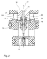
- Fig. 1 shows the variant Fig. 2 a varied control piece 21 and a modified embodiment of the core 30 with a (with respect to the axis of the control pin 20) concentric elevation 31st
- control piece 21 is also funnel-like or cone-like seen from the outside again.
- the functionality of the rule shown here is identical to that of Fig. 1 comparable and equivalent.
- the rule 21 has arisen in a plastic extrusion process, resulting in slightly larger wall thicknesses.
- the wall thickness itself is not the same everywhere, this can be realized by appropriate embodiments of the injection molding tool.
- fiber-reinforced plastic for example, carbon fiber or glass fiber reinforced plastic
- high temperature resistant plastic or high-strength plastic existing rule 21 is also provided on the control pin 20, an annular groove 24 or possibly other surface recesses, creating a positive connection between control pin 20th and Rule 21 is achieved.
- an elevation 31 facing the valve seat 11 is arranged concentrically around the bearing of the pin 20 in the core 30 on the core 30. Regardless of the axial position 27 of the pin 20 (and therefore of the control piece 21), this increase 31 is in the chamber 22 of the control piece 21 a. But there remains a small opening gap (annular) between the elevation 31 and the annular portion 202, through which also the medium to be controlled can flow. By this construction is achieved that there is a higher stability against pressure oscillations.
Landscapes
- Engineering & Computer Science (AREA)
- General Engineering & Computer Science (AREA)
- Mechanical Engineering (AREA)
- Magnetically Actuated Valves (AREA)
Applications Claiming Priority (1)
| Application Number | Priority Date | Filing Date | Title |
|---|---|---|---|
| DE102009035902 | 2009-08-03 |
Publications (2)
| Publication Number | Publication Date |
|---|---|
| EP2282090A2 true EP2282090A2 (fr) | 2011-02-09 |
| EP2282090A3 EP2282090A3 (fr) | 2013-11-20 |
Family
ID=42830711
Family Applications (1)
| Application Number | Title | Priority Date | Filing Date |
|---|---|---|---|
| EP20100008045 Withdrawn EP2282090A3 (fr) | 2009-08-03 | 2010-08-02 | Soupape, en particulier soupape de réglage de pression |
Country Status (3)
| Country | Link |
|---|---|
| US (1) | US9103462B2 (fr) |
| EP (1) | EP2282090A3 (fr) |
| DE (1) | DE102010033032A1 (fr) |
Families Citing this family (2)
| Publication number | Priority date | Publication date | Assignee | Title |
|---|---|---|---|---|
| DE102013107390B4 (de) * | 2013-07-12 | 2023-06-07 | Svm Schultz Verwaltungs-Gmbh & Co. Kg | Druckregelventil mit Regelelement |
| DE102013220877A1 (de) * | 2013-10-15 | 2015-04-16 | Continental Automotive Gmbh | Ventil |
Family Cites Families (13)
| Publication number | Priority date | Publication date | Assignee | Title |
|---|---|---|---|---|
| US788536A (en) * | 1903-03-14 | 1905-05-02 | John Patrick O Donnell | Pneumatic railway signaling system and electropneumatic valve therefor. |
| US2283903A (en) * | 1940-04-29 | 1942-05-26 | Honeywell Regulator Co | Valve |
| US2521308A (en) * | 1945-12-22 | 1950-09-05 | Louis M Porter | Vent structure for incubators |
| US2612188A (en) * | 1947-04-11 | 1952-09-30 | Mcquay Norris Mfg Co | Solenoid-operated gas valve |
| US3955795A (en) * | 1973-11-15 | 1976-05-11 | Refreshment Machinery Incorporated | Valve |
| US4304258A (en) * | 1979-10-15 | 1981-12-08 | The Garrett Corporation | Solenoid valve assembly |
| US5526837A (en) * | 1994-12-01 | 1996-06-18 | Robertshaw Controls Company | Solenoid controlled one-way valve |
| DE10023329A1 (de) * | 2000-05-12 | 2001-11-15 | Bosch Gmbh Robert | Ventil |
| DE10023582A1 (de) * | 2000-05-13 | 2001-11-15 | Bosch Gmbh Robert | Ventil mit elastischen Dichtelementen |
| DE10351504A1 (de) * | 2003-11-05 | 2005-06-02 | Robert Bosch Gmbh | Elektromagnetisches Druckventil |
| DE102005059433A1 (de) * | 2005-12-13 | 2007-06-14 | Robert Bosch Gmbh | Druckregelventil mit Massivlager |
| DE102007035472A1 (de) * | 2007-07-26 | 2009-01-29 | Svm Schultz Verwaltungs-Gmbh & Co. Kg | Ventil |
| DE102009004803A1 (de) * | 2008-01-17 | 2009-07-23 | Eto Magnetic Gmbh | Elektromagnetisch betätigbare Ventilvorrichtung |
-
2010
- 2010-08-02 DE DE102010033032A patent/DE102010033032A1/de not_active Withdrawn
- 2010-08-02 EP EP20100008045 patent/EP2282090A3/fr not_active Withdrawn
- 2010-08-03 US US12/805,507 patent/US9103462B2/en active Active
Non-Patent Citations (1)
| Title |
|---|
| None |
Also Published As
| Publication number | Publication date |
|---|---|
| EP2282090A3 (fr) | 2013-11-20 |
| US9103462B2 (en) | 2015-08-11 |
| DE102010033032A1 (de) | 2011-02-10 |
| US20110042596A1 (en) | 2011-02-24 |
Similar Documents
| Publication | Publication Date | Title |
|---|---|---|
| EP2308064B1 (fr) | Système d électroaimant de levage et système de soupape | |
| EP3206214B1 (fr) | Dispositif électromagnétique et dispositif d'aide au conducteur | |
| EP2685145A2 (fr) | Soupape | |
| EP2759749A1 (fr) | Soupape de fluide électromagnétique | |
| EP4031786B1 (fr) | Électrovanne pour véhicule automobile et procédé de production d'une unité déplacement à partir d'une armature et unité vanne pour électrovanne de ce type | |
| EP2405167A2 (fr) | Soupape électromagnétique pour un moteur à combustion interne | |
| EP3358233B1 (fr) | Soupape, en particulier soupape à tiroir | |
| DE102007035472A1 (de) | Ventil | |
| AT510989B1 (de) | Durchflussmengenbegrenzungseinrichtung | |
| EP2282090A2 (fr) | Soupape, en particulier soupape de réglage de pression | |
| EP2299458B1 (fr) | Électroaimant | |
| DE102013107390B4 (de) | Druckregelventil mit Regelelement | |
| DE102005023547A1 (de) | Elektrisch ansteuerbares Ventil | |
| EP3545185B1 (fr) | Valve de dosage de gaz | |
| WO2016058773A1 (fr) | Soupape d'injection de carburant | |
| EP3312853A1 (fr) | Électro-aimant | |
| DE10321154A1 (de) | Ventil | |
| DE102013107389B4 (de) | Druckregelventil | |
| EP1734541A2 (fr) | Électroaimant avec cône de contrôle | |
| EP2527945A2 (fr) | Soupape de réglage de pression avec écran | |
| DE102012104715A1 (de) | Magnetischer Ventilaktuator | |
| EP2405168B1 (fr) | Corps de soupape et soupape électromagnétique correspondante | |
| EP2966658B1 (fr) | Électroaimant et module de barre d'ancrage | |
| WO2020020836A1 (fr) | Soupape | |
| EP2185808B1 (fr) | Soupape d'injection de carburant pour moteurs à combustion interne |
Legal Events
| Date | Code | Title | Description |
|---|---|---|---|
| PUAI | Public reference made under article 153(3) epc to a published international application that has entered the european phase |
Free format text: ORIGINAL CODE: 0009012 |
|
| AK | Designated contracting states |
Kind code of ref document: A2 Designated state(s): AL AT BE BG CH CY CZ DE DK EE ES FI FR GB GR HR HU IE IS IT LI LT LU LV MC MK MT NL NO PL PT RO SE SI SK SM TR |
|
| AX | Request for extension of the european patent |
Extension state: BA ME RS |
|
| PUAL | Search report despatched |
Free format text: ORIGINAL CODE: 0009013 |
|
| AK | Designated contracting states |
Kind code of ref document: A3 Designated state(s): AL AT BE BG CH CY CZ DE DK EE ES FI FR GB GR HR HU IE IS IT LI LT LU LV MC MK MT NL NO PL PT RO SE SI SK SM TR |
|
| AX | Request for extension of the european patent |
Extension state: BA ME RS |
|
| RIC1 | Information provided on ipc code assigned before grant |
Ipc: F16K 31/06 20060101AFI20131011BHEP |
|
| STAA | Information on the status of an ep patent application or granted ep patent |
Free format text: STATUS: THE APPLICATION IS DEEMED TO BE WITHDRAWN |
|
| 18D | Application deemed to be withdrawn |
Effective date: 20140521 |