EP2282104A2 - Wickelstativ - Google Patents
Wickelstativ Download PDFInfo
- Publication number
- EP2282104A2 EP2282104A2 EP09173191A EP09173191A EP2282104A2 EP 2282104 A2 EP2282104 A2 EP 2282104A2 EP 09173191 A EP09173191 A EP 09173191A EP 09173191 A EP09173191 A EP 09173191A EP 2282104 A2 EP2282104 A2 EP 2282104A2
- Authority
- EP
- European Patent Office
- Prior art keywords
- movable joint
- hoverball
- winding
- movable
- hole
- Prior art date
- Legal status (The legal status is an assumption and is not a legal conclusion. Google has not performed a legal analysis and makes no representation as to the accuracy of the status listed.)
- Withdrawn
Links
- 238000004804 winding Methods 0.000 title claims abstract description 26
- 230000008878 coupling Effects 0.000 claims abstract description 9
- 238000010168 coupling process Methods 0.000 claims abstract description 9
- 238000005859 coupling reaction Methods 0.000 claims abstract description 9
- 210000005069 ears Anatomy 0.000 claims description 9
- 230000007547 defect Effects 0.000 description 3
- 102100040428 Chitobiosyldiphosphodolichol beta-mannosyltransferase Human genes 0.000 description 2
- 238000005516 engineering process Methods 0.000 description 2
- 229910000838 Al alloy Inorganic materials 0.000 description 1
- 239000002131 composite material Substances 0.000 description 1
- 239000007769 metal material Substances 0.000 description 1
- 238000012986 modification Methods 0.000 description 1
- 230000004048 modification Effects 0.000 description 1
- 229910052755 nonmetal Inorganic materials 0.000 description 1
- 239000010935 stainless steel Substances 0.000 description 1
- 229910001256 stainless steel alloy Inorganic materials 0.000 description 1
Images



Classifications
-
- F—MECHANICAL ENGINEERING; LIGHTING; HEATING; WEAPONS; BLASTING
- F16—ENGINEERING ELEMENTS AND UNITS; GENERAL MEASURES FOR PRODUCING AND MAINTAINING EFFECTIVE FUNCTIONING OF MACHINES OR INSTALLATIONS; THERMAL INSULATION IN GENERAL
- F16M—FRAMES, CASINGS OR BEDS OF ENGINES, MACHINES OR APPARATUS, NOT SPECIFIC TO ENGINES, MACHINES OR APPARATUS PROVIDED FOR ELSEWHERE; STANDS; SUPPORTS
- F16M11/00—Stands or trestles as supports for apparatus or articles placed thereon ; Stands for scientific apparatus such as gravitational force meters
- F16M11/20—Undercarriages with or without wheels
- F16M11/24—Undercarriages with or without wheels changeable in height or length of legs, also for transport only, e.g. by means of tubes screwed into each other
- F16M11/40—Undercarriages with or without wheels changeable in height or length of legs, also for transport only, e.g. by means of tubes screwed into each other by means of coilable or bendable legs or spiral shaped legs
Definitions
- the present invention relates to a photography device, and particularly to a winding tripod.
- a tripod is generally used for supporting a camera or vidicon when the camera or vidicon is used to take photos. Moreover, the tripod can be adjusted to meet the requirements on the shooting angle.
- a winding tripod In order to facilitate adjustment of the shooting angle, a winding tripod currently appears, that is, the legs of the tripod can be flexibly wound around other objects.
- links of the legs of most of the prior art winding tripods are connected together via a plurality of ball-cradle head universal joints therebetween, and the wound legs of the tripod are very easy to be unwound and stretched due to small friction force of the ball-cradle head universal joints, which may result in falling and damaging of the camera or vidicon mounted on the tripod.
- a purpose of the present invention is to provide a winding tripod that can be wound firmly and wound/unwound flexibly.
- the winding tripod of the present invention includes a cradle head and three legs, wherein each of the legs is connected at one end thereof with the cradle head via a universal joint and supported at the other end on the ground. At least one of the legs therein includes a plurality of first movable joints and a plurality of second movable joints, wherein said first and second movable joints are connected together alternately and hinged via a locking coupling device, so that the first movable joint and the second movable joint are capable of pivot with respect to each other..
- first and the second movable joints each are provided with a hoverball hole. Between the first and the second movable joints are positioned a spring and a hoverball. The spring pushes the hoverball and thus the hoverball is clipped into the hoverball hole when the first movable joint is pivoted to one of a plurality of predetermined angles with respect to the second movable joints.
- the spring when the first movable joint is pivoted towards another one of the plurality of predetermined angles with respect to the second movable joint, during the pivoting movement, the spring is retracted, so that the hoverball is disengaged with the hoverball hole, and when the first movable joint is pivoted and reach the another one of the plurality of predetermined angles with respect to the second movable joint, the spring pushes the hoverball once more, so that the hoverball is clipped into the hoverball hole again.
- the locking coupling device includes a male butt rivet and a female butt rivet used as a hinge axis, which are riveted together and make an interference fit with a hinge hole on the first and the second movable joints. It is more preferred that the magnitude of interference of the interference fit is 0.1-0.3 mm.
- the tripod further includes a rubber ring, with which the outer circumference of the second movable joint is muff-coupled.
- the hoverball is clipped into the hoverball hole when a pivotal angle between the first movable joint and the second movable joint is 180 degrees.
- first movable joint and the second movable joint each are provided with a chute, on which is positioned the hoverball hole.
- the first movable joint includes two first connection sections, each of which is provided with a through hole.
- the second movable joint includes two second connection sections, each of which is provided with double ears fitted with the first connection sections, and the double ears are provided with a through hole.
- the tripod further includes a mat and a footmuff supported on the ground, the mat is muff-coupled with the footmuff, and the footmuff is hinged to the second movable joint via the locking coupling device.
- the winding tripod of the present invention can overcome the defects of the prior art technology.
- a universal joint structure without a security function is replaced with a three-dimensional structure with the security function, which thus enables the windable legs to be wound firmly around any surface and winding and unwinding of the legs to be more flexible.
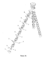
- the winding tripod of the present invention includes three legs 100s and a cradle head 200, each of the legs 100 connected at one end with the cradle head 200 via a universal joint and spherically rotatable around the cradle head 200.
- At least one of the legs 100 includes a plurality of first movable joints 7 and a plurality of second movable joints 9.
- first movable joints 7 and the second movable joints 9 are connected together alternately and hinged via a locking coupling device; that is, one of the first movable joints 7 is hinged to one of the second movable joints 9, this second movable joint 9 is in turn hinged to another one of the first movable joints 7, and so on.
- the connection length can be determined based on actual application.
- Each of the legs 100 is composed of a plurality of movable joints hinged together.
- the first movable joints 7 and the second movable joints 9 can make a pitching movement through pivoting around a hinge axis.
- each of the movable joints can be pivoted, making the tripod unbent or bent into a particular shape.
- it can be wound up.
- a butt rivet is used between the first movable joint 7 and the second movable joint 9.
- the butt rivet including a male butt rivet 3 and a female butt rivet 4, is interference-fitted with holes on the first movable joint 7 and the second movable joint 9, so as to produce an enough winding force.
- the friction force between each pair of first movable joint 7 and second movable joints 9 can reach about 10-50 N, and the amount of the friction force, i.e.
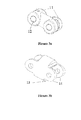
- the first movable joint 7 includes two first connection sections 11, which are hinged to the two adjacent second movable joints 9, respectively, each of the first connection sections 11s having a through hole 12.
- the second movable joint 9 also has two second connection sections 13, each of which has “double ears" 14 matched with the first connection section on the first movable joint 7.
- Each of the ears 14 has a hole, the diameter of which is substantially consistent with diameter of the through hole on the connection section of the first movable joint 7.
- connection section 13 shown in Figure 3b is provided with two ears, it can be understood that, in order to more firmly connect the first movable joint 7 with the second movable 9, the ears can be designed so that the number of the ears is more than 2, and thus the connection section 11 is designed in the corresponding shape.
- first movable joint 7 and the second movable joint 9 may have other shape and structure, so long as both of them ar connected together via a hinge having locking connection, without going beyond the protection scope of the present invention.
- the first movable joint 7 and the second movable joint 9 each are provided with a hoverball hole. Between the first and the second movable joints are positioned a spring 5 and a hoverball 6. Under the action of the elastic force of the spring 5, the hoverball 6 is pushed and clipped into the hoverball hole when the first movable joint is pivoted a predetermined angle with respect to the second movable joint.
- the spring 5 is ejected outwardly from both ends thereof and pushes the hoverball 6, and thus the hoverball 6 is clipped into the hoverball hole when the leg 100 is unbent; that is, the hoverball 6 is clipped into the hoverball hole when the pivotal angle between the first movable joint 7 and the second movable joint 9 is 180 degrees.
- the pivotal angle mentioned herein between the first movable joint 7 and the second movable joint 9 means the included angle between major axes of the first movable joint 7 and the second movable joint 9.
- said predetermined pivotal angle is not limited in 180 degree. That is to say, the first movable joint 7 and the second movable joint 9 can be fixed at a plurality of predetermined pivotal angles.
- the legs When the legs are unbent, if it is desirable to wind the legs, an operator may pivot the first movable joint 7 and the second movable joint 9. During pivoting of the movable joints, the spring 7 pulls the hoverball 6 backwards, so that the hoverball 6 is disengaged with the hoverball hole. When the first movable joint 7 and the second movable 9 pivot to another pivotal angle and stop there, the spring 5 pushes the hoverball 6 outwards once again, so that the hoverball 6 is clipped into the hoverball hole and thus the legs are stable at said another pivotal angle. Therefore, it is achieved that the legs can be wound/unwound more flexibly.
- a sound is usually made when the spring 5 pushes the hoverball 6 to be clipped into the hoverball hole, thus reminding an operator that the corresponding movable joints have already been pivoted in place.
- the hoverball hole is positioned on the connection sections of the first movable joint 7 and the second movable joint 9.
- the first connection section 11 and the second connection section 13 movably connected as mentioned above are provided with an orbital chute, and the hoverball hole can be positioned at the middle point of the chute and has a shape of a hemisphere recess matching with the hoverball 6.
- a rubber ring 8 can be positioned on the second movable joint 9, so as to further increase the friction force during the winding of the legs 100 and thus make the legs 100 wound more firmly.
- the outer circumferential surface of the second movable joint 9 is provided with a shallow groove, with which the rubber ring 8 is muff-coupled.
- the tripod can further include a mat 1 and a footmuff 2, wherein the footmuff 2 is connected to the end of the leg 100, and the mat 1 is muff-coupled with the footmuff 2 to protect the footmuff 2 and support the tripod on the ground.
- the footmuff is hinged to the second movable joint via the locking coupling device.
- At least one of the legs 100 is provided with locking hinge connection. It is preferred that all of the three legs are provided with the locking hinge connections.
- the first movable joint 7 and the second movable joint 9 can be made of such metal materials as stainless steel and aluminum alloy or the like, or appropriate nonmetal or composite materials.
Landscapes
- Engineering & Computer Science (AREA)
- General Engineering & Computer Science (AREA)
- Mechanical Engineering (AREA)
- Accessories Of Cameras (AREA)
- Studio Devices (AREA)
Applications Claiming Priority (1)
| Application Number | Priority Date | Filing Date | Title |
|---|---|---|---|
| CN200910162450XA CN101988615B (zh) | 2009-08-05 | 2009-08-05 | 缠绕式三脚架 |
Publications (2)
| Publication Number | Publication Date |
|---|---|
| EP2282104A2 true EP2282104A2 (de) | 2011-02-09 |
| EP2282104A3 EP2282104A3 (de) | 2012-01-04 |
Family
ID=43127059
Family Applications (1)
| Application Number | Title | Priority Date | Filing Date |
|---|---|---|---|
| EP09173191A Withdrawn EP2282104A3 (de) | 2009-08-05 | 2009-10-15 | Wickelstativ |
Country Status (4)
| Country | Link |
|---|---|
| US (1) | US20110031359A1 (de) |
| EP (1) | EP2282104A3 (de) |
| JP (1) | JP2011034037A (de) |
| CN (1) | CN101988615B (de) |
Families Citing this family (11)
| Publication number | Priority date | Publication date | Assignee | Title |
|---|---|---|---|---|
| CN102853220A (zh) * | 2012-09-13 | 2013-01-02 | 中国科学院长春光学精密机械与物理研究所 | 一种铰链式空间遥感相机支架 |
| US8857775B1 (en) | 2013-07-22 | 2014-10-14 | Gopro, Inc. | Camera mount with spring clamp |
| US20150049500A1 (en) * | 2013-08-14 | 2015-02-19 | Ford Global Technologies, Llc | Vehicle interior and portable accessory light assembly |
| CN103606829A (zh) * | 2013-11-04 | 2014-02-26 | 国家电网公司 | 一种蜘蛛式高空工作台架 |
| CN104110562A (zh) * | 2014-06-22 | 2014-10-22 | 苏州金螳螂住宅集成装饰有限公司 | 无障碍三角架 |
| US10289919B2 (en) * | 2015-01-27 | 2019-05-14 | Hyundai Motor Company | Vehicle and method of controlling the same |
| JP5838437B1 (ja) * | 2015-04-15 | 2016-01-06 | スリック株式会社 | カメラ支持具 |
| USD758474S1 (en) | 2015-05-07 | 2016-06-07 | Gopro, Inc. | Camera mount |
| CN105792053B (zh) * | 2016-05-14 | 2018-09-07 | 青岛歌尔声学科技有限公司 | 一种麦克杆结构 |
| USD921095S1 (en) | 2019-06-19 | 2021-06-01 | Gopro, Inc. | Camera mount |
| USD989847S1 (en) * | 2020-11-24 | 2023-06-20 | Ningbo Yizhou Machinery Co., Ltd. | Tripod |
Citations (1)
| Publication number | Priority date | Publication date | Assignee | Title |
|---|---|---|---|---|
| US3825356A (en) * | 1972-07-14 | 1974-07-23 | American Hoist & Derrick Co | Two-piece swage fittings |
Family Cites Families (26)
| Publication number | Priority date | Publication date | Assignee | Title |
|---|---|---|---|---|
| US255103A (en) * | 1882-03-21 | Shaft-coupling | ||
| US816240A (en) * | 1905-05-22 | 1906-03-27 | Charles F C Mehlig | Flexible shaft. |
| US2533494A (en) * | 1949-02-18 | 1950-12-12 | Jr Iverson O Mitchell | Adjustable article support |
| US3986692A (en) * | 1974-04-04 | 1976-10-19 | Olympus Optical Co., Ltd. | Apparatus for supporting articles |
| US4491435A (en) * | 1983-07-18 | 1985-01-01 | Automated Medical Products Corporation | Jointed stand |
| US4685349A (en) * | 1985-12-20 | 1987-08-11 | Agency Of Industrial Science And Technology | Flexibly foldable arm |
| JPH03129333A (ja) * | 1989-10-14 | 1991-06-03 | Konica Corp | カメラ用三脚 |
| US5348259A (en) * | 1992-02-10 | 1994-09-20 | Massachusetts Institute Of Technology | Flexible, articulable column |
| GB9309434D0 (en) * | 1993-05-07 | 1993-06-23 | Potter George A J | Golf training clubs |
| WO1997011283A2 (de) * | 1995-09-19 | 1997-03-27 | Norbert Noetzold | Ein aus formteilen bestehendes zug/druck-kraftübertragungssystem |
| US5899627A (en) * | 1996-09-12 | 1999-05-04 | Minnesota Scientific, Inc. | Clamp for retractor support |
| DE10019321C2 (de) * | 2000-04-19 | 2002-03-14 | Storz Karl Gmbh & Co Kg | Flexible Spannvorrichtung ,insbesondere für medizinische Zwecke |
| US6607684B1 (en) * | 2000-09-19 | 2003-08-19 | C. J. Associates, Ltd. | Method of making a jointed linkage support system |
| US6819550B2 (en) * | 2001-11-08 | 2004-11-16 | Apple Computer, Inc. | Computer controlled display device |
| US6672788B2 (en) * | 2002-02-04 | 2004-01-06 | Clarence Eduard Hathaway | Ball joint with detent action |
| US7369672B2 (en) * | 2002-06-24 | 2008-05-06 | Hirschhorn Bruce D | Personal audio visual system |
| US6749166B2 (en) * | 2002-11-13 | 2004-06-15 | Mike Valentine | Flashlight holder |
| US6767153B1 (en) * | 2003-02-10 | 2004-07-27 | Dana W. Holbrook | Locking positional arm device |
| US7959116B2 (en) * | 2004-03-17 | 2011-06-14 | Carnevali Jeffrey D | Configurable mounting bracket |
| US20070154254A1 (en) * | 2006-01-03 | 2007-07-05 | Bevirt Joeben | Mounting apparatus using ball and socket joints with gripping features |
| CN200972043Y (zh) * | 2006-11-23 | 2007-11-07 | 赵勇 | 自定位微型三脚架 |
| CN201003676Y (zh) * | 2006-12-29 | 2008-01-09 | 邓慧雯 | 一种可变形的固定结构及采用这种结构的便携式三脚架 |
| US20090039213A1 (en) * | 2007-04-27 | 2009-02-12 | Richard Darrow | Apparatuses and systems for supporting and positioning cameras and other equipment |
| US7621491B2 (en) * | 2007-07-26 | 2009-11-24 | Hung Hi Law | Portable supporting apparatus |
| CN100592193C (zh) * | 2007-10-17 | 2010-02-24 | 鸿富锦精密工业(深圳)有限公司 | 相机脚架 |
| CN201110449Y (zh) * | 2007-11-24 | 2008-09-03 | 陆伟明 | 照相机三脚架支脚连接机构 |
-
2009
- 2009-08-05 CN CN200910162450XA patent/CN101988615B/zh not_active Expired - Fee Related
- 2009-10-15 EP EP09173191A patent/EP2282104A3/de not_active Withdrawn
- 2009-10-21 JP JP2009242301A patent/JP2011034037A/ja active Pending
- 2009-10-23 US US12/604,451 patent/US20110031359A1/en not_active Abandoned
Patent Citations (1)
| Publication number | Priority date | Publication date | Assignee | Title |
|---|---|---|---|---|
| US3825356A (en) * | 1972-07-14 | 1974-07-23 | American Hoist & Derrick Co | Two-piece swage fittings |
Also Published As
| Publication number | Publication date |
|---|---|
| US20110031359A1 (en) | 2011-02-10 |
| CN101988615B (zh) | 2012-08-08 |
| CN101988615A (zh) | 2011-03-23 |
| EP2282104A3 (de) | 2012-01-04 |
| JP2011034037A (ja) | 2011-02-17 |
Similar Documents
| Publication | Publication Date | Title |
|---|---|---|
| EP2282104A2 (de) | Wickelstativ | |
| US10051163B2 (en) | 180 degree bendable articulating borescope endoscope | |
| EP3091730B1 (de) | Zugstangenartige digitalkamera | |
| US10088096B2 (en) | Portable stand for electronic device | |
| US20160273703A1 (en) | A Clamping Device for a Camera Device | |
| US9332170B1 (en) | Telescoping extension | |
| US8830391B2 (en) | Telescoping monopod camera holding apparatus and method | |
| US10365501B2 (en) | Hinge assembly and glasses frame | |
| CN207880407U (zh) | 手持云台 | |
| US20160146571A1 (en) | Multi-Axis Swivel Connector | |
| WO2017080337A1 (zh) | 摄影加长杆及拍摄装置 | |
| US20120288268A1 (en) | Miniature Mounting Apparatus | |
| CN205048104U (zh) | 自拍杆及具有该自拍杆的电子产品支架 | |
| US20110160005A1 (en) | Sports Goal Structure with Quick-Release Joint | |
| US20130272687A1 (en) | Frame for mounting reflecting plate and background sheet for picture and video shooting thereon | |
| CN108634543A (zh) | 一种杆件及拉杆背包 | |
| US20240223934A1 (en) | Headphone capable of being bent outward | |
| KR101170964B1 (ko) | 카메라 지지장치 | |
| CN211793685U (zh) | 一种项圈 | |
| CN206770924U (zh) | 一种摄影摇臂及摄影装置 | |
| US20160317852A1 (en) | Exercising Assembly | |
| AU2006100610A4 (en) | Connector | |
| CN204756341U (zh) | 自拍器云台 | |
| US20180170236A1 (en) | Mounting assembly | |
| CN107175143B (zh) | 一种防试管晃动的滴水架 |
Legal Events
| Date | Code | Title | Description |
|---|---|---|---|
| PUAI | Public reference made under article 153(3) epc to a published international application that has entered the european phase |
Free format text: ORIGINAL CODE: 0009012 |
|
| AK | Designated contracting states |
Kind code of ref document: A2 Designated state(s): AT BE BG CH CY CZ DE DK EE ES FI FR GB GR HR HU IE IS IT LI LT LU LV MC MK MT NL NO PL PT RO SE SI SK SM TR |
|
| AX | Request for extension of the european patent |
Extension state: AL BA RS |
|
| PUAL | Search report despatched |
Free format text: ORIGINAL CODE: 0009013 |
|
| AK | Designated contracting states |
Kind code of ref document: A3 Designated state(s): AT BE BG CH CY CZ DE DK EE ES FI FR GB GR HR HU IE IS IT LI LT LU LV MC MK MT NL NO PL PT RO SE SI SK SM TR |
|
| AX | Request for extension of the european patent |
Extension state: AL BA RS |
|
| RIC1 | Information provided on ipc code assigned before grant |
Ipc: F16M 11/32 20060101ALN20111125BHEP Ipc: F16M 11/40 20060101AFI20111125BHEP |
|
| 17P | Request for examination filed |
Effective date: 20120328 |
|
| 17Q | First examination report despatched |
Effective date: 20130222 |
|
| STAA | Information on the status of an ep patent application or granted ep patent |
Free format text: STATUS: THE APPLICATION IS DEEMED TO BE WITHDRAWN |
|
| 18D | Application deemed to be withdrawn |
Effective date: 20130705 |