EP2282373B1 - Câble électrique serti avec borne et son procédé de production - Google Patents
Câble électrique serti avec borne et son procédé de production Download PDFInfo
- Publication number
- EP2282373B1 EP2282373B1 EP10008298.1A EP10008298A EP2282373B1 EP 2282373 B1 EP2282373 B1 EP 2282373B1 EP 10008298 A EP10008298 A EP 10008298A EP 2282373 B1 EP2282373 B1 EP 2282373B1
- Authority
- EP
- European Patent Office
- Prior art keywords
- electric wire
- crimping
- terminal fitting
- section
- crimping section
- Prior art date
- Legal status (The legal status is an assumption and is not a legal conclusion. Google has not performed a legal analysis and makes no representation as to the accuracy of the status listed.)
- Not-in-force
Links
- 238000004519 manufacturing process Methods 0.000 title claims description 4
- 238000002788 crimping Methods 0.000 claims description 94
- 230000006835 compression Effects 0.000 claims description 44
- 238000007906 compression Methods 0.000 claims description 44
- XAGFODPZIPBFFR-UHFFFAOYSA-N aluminium Chemical compound [Al] XAGFODPZIPBFFR-UHFFFAOYSA-N 0.000 claims description 19
- 229910052782 aluminium Inorganic materials 0.000 claims description 19
- 229910000838 Al alloy Inorganic materials 0.000 claims description 5
- 238000000034 method Methods 0.000 claims description 5
- 230000000630 rising effect Effects 0.000 claims description 5
- 230000035939 shock Effects 0.000 description 8
- RYGMFSIKBFXOCR-UHFFFAOYSA-N Copper Chemical compound [Cu] RYGMFSIKBFXOCR-UHFFFAOYSA-N 0.000 description 7
- 229910052802 copper Inorganic materials 0.000 description 7
- 239000010949 copper Substances 0.000 description 7
- 229910000881 Cu alloy Inorganic materials 0.000 description 3
- 239000004411 aluminium Substances 0.000 description 3
- 239000012141 concentrate Substances 0.000 description 3
- 238000009413 insulation Methods 0.000 description 3
- 239000000463 material Substances 0.000 description 3
- 230000001747 exhibiting effect Effects 0.000 description 2
- 229910001369 Brass Inorganic materials 0.000 description 1
- 239000010951 brass Substances 0.000 description 1
- 239000004020 conductor Substances 0.000 description 1
- 230000007423 decrease Effects 0.000 description 1
- 230000000694 effects Effects 0.000 description 1
- 230000013011 mating Effects 0.000 description 1
Images





Classifications
-
- H—ELECTRICITY
- H01—ELECTRIC ELEMENTS
- H01R—ELECTRICALLY-CONDUCTIVE CONNECTIONS; STRUCTURAL ASSOCIATIONS OF A PLURALITY OF MUTUALLY-INSULATED ELECTRICAL CONNECTING ELEMENTS; COUPLING DEVICES; CURRENT COLLECTORS
- H01R4/00—Electrically-conductive connections between two or more conductive members in direct contact, i.e. touching one another; Means for effecting or maintaining such contact; Electrically-conductive connections having two or more spaced connecting locations for conductors and using contact members penetrating insulation
- H01R4/10—Electrically-conductive connections between two or more conductive members in direct contact, i.e. touching one another; Means for effecting or maintaining such contact; Electrically-conductive connections having two or more spaced connecting locations for conductors and using contact members penetrating insulation effected solely by twisting, wrapping, bending, crimping, or other permanent deformation
- H01R4/18—Electrically-conductive connections between two or more conductive members in direct contact, i.e. touching one another; Means for effecting or maintaining such contact; Electrically-conductive connections having two or more spaced connecting locations for conductors and using contact members penetrating insulation effected solely by twisting, wrapping, bending, crimping, or other permanent deformation by crimping
- H01R4/20—Electrically-conductive connections between two or more conductive members in direct contact, i.e. touching one another; Means for effecting or maintaining such contact; Electrically-conductive connections having two or more spaced connecting locations for conductors and using contact members penetrating insulation effected solely by twisting, wrapping, bending, crimping, or other permanent deformation by crimping using a crimping sleeve
- H01R4/203—Electrically-conductive connections between two or more conductive members in direct contact, i.e. touching one another; Means for effecting or maintaining such contact; Electrically-conductive connections having two or more spaced connecting locations for conductors and using contact members penetrating insulation effected solely by twisting, wrapping, bending, crimping, or other permanent deformation by crimping using a crimping sleeve having an uneven wire-receiving surface to improve the contact
- H01R4/206—Electrically-conductive connections between two or more conductive members in direct contact, i.e. touching one another; Means for effecting or maintaining such contact; Electrically-conductive connections having two or more spaced connecting locations for conductors and using contact members penetrating insulation effected solely by twisting, wrapping, bending, crimping, or other permanent deformation by crimping using a crimping sleeve having an uneven wire-receiving surface to improve the contact with transversal grooves or threads
-
- H—ELECTRICITY
- H01—ELECTRIC ELEMENTS
- H01R—ELECTRICALLY-CONDUCTIVE CONNECTIONS; STRUCTURAL ASSOCIATIONS OF A PLURALITY OF MUTUALLY-INSULATED ELECTRICAL CONNECTING ELEMENTS; COUPLING DEVICES; CURRENT COLLECTORS
- H01R4/00—Electrically-conductive connections between two or more conductive members in direct contact, i.e. touching one another; Means for effecting or maintaining such contact; Electrically-conductive connections having two or more spaced connecting locations for conductors and using contact members penetrating insulation
- H01R4/10—Electrically-conductive connections between two or more conductive members in direct contact, i.e. touching one another; Means for effecting or maintaining such contact; Electrically-conductive connections having two or more spaced connecting locations for conductors and using contact members penetrating insulation effected solely by twisting, wrapping, bending, crimping, or other permanent deformation
- H01R4/18—Electrically-conductive connections between two or more conductive members in direct contact, i.e. touching one another; Means for effecting or maintaining such contact; Electrically-conductive connections having two or more spaced connecting locations for conductors and using contact members penetrating insulation effected solely by twisting, wrapping, bending, crimping, or other permanent deformation by crimping
- H01R4/183—Electrically-conductive connections between two or more conductive members in direct contact, i.e. touching one another; Means for effecting or maintaining such contact; Electrically-conductive connections having two or more spaced connecting locations for conductors and using contact members penetrating insulation effected solely by twisting, wrapping, bending, crimping, or other permanent deformation by crimping for cylindrical elongated bodies, e.g. cables having circular cross-section
- H01R4/184—Electrically-conductive connections between two or more conductive members in direct contact, i.e. touching one another; Means for effecting or maintaining such contact; Electrically-conductive connections having two or more spaced connecting locations for conductors and using contact members penetrating insulation effected solely by twisting, wrapping, bending, crimping, or other permanent deformation by crimping for cylindrical elongated bodies, e.g. cables having circular cross-section comprising a U-shaped wire-receiving portion
- H01R4/185—Electrically-conductive connections between two or more conductive members in direct contact, i.e. touching one another; Means for effecting or maintaining such contact; Electrically-conductive connections having two or more spaced connecting locations for conductors and using contact members penetrating insulation effected solely by twisting, wrapping, bending, crimping, or other permanent deformation by crimping for cylindrical elongated bodies, e.g. cables having circular cross-section comprising a U-shaped wire-receiving portion combined with a U-shaped insulation-receiving portion
-
- H—ELECTRICITY
- H01—ELECTRIC ELEMENTS
- H01R—ELECTRICALLY-CONDUCTIVE CONNECTIONS; STRUCTURAL ASSOCIATIONS OF A PLURALITY OF MUTUALLY-INSULATED ELECTRICAL CONNECTING ELEMENTS; COUPLING DEVICES; CURRENT COLLECTORS
- H01R43/00—Apparatus or processes specially adapted for manufacturing, assembling, maintaining, or repairing of line connectors or current collectors or for joining electric conductors
- H01R43/04—Apparatus or processes specially adapted for manufacturing, assembling, maintaining, or repairing of line connectors or current collectors or for joining electric conductors for forming connections by deformation, e.g. crimping tool
- H01R43/048—Crimping apparatus or processes
- H01R43/0488—Crimping apparatus or processes with crimp height adjusting means
-
- H—ELECTRICITY
- H01—ELECTRIC ELEMENTS
- H01R—ELECTRICALLY-CONDUCTIVE CONNECTIONS; STRUCTURAL ASSOCIATIONS OF A PLURALITY OF MUTUALLY-INSULATED ELECTRICAL CONNECTING ELEMENTS; COUPLING DEVICES; CURRENT COLLECTORS
- H01R4/00—Electrically-conductive connections between two or more conductive members in direct contact, i.e. touching one another; Means for effecting or maintaining such contact; Electrically-conductive connections having two or more spaced connecting locations for conductors and using contact members penetrating insulation
- H01R4/58—Electrically-conductive connections between two or more conductive members in direct contact, i.e. touching one another; Means for effecting or maintaining such contact; Electrically-conductive connections having two or more spaced connecting locations for conductors and using contact members penetrating insulation characterised by the form or material of the contacting members
- H01R4/62—Connections between conductors of different materials; Connections between or with aluminium or steel-core aluminium conductors
-
- H—ELECTRICITY
- H01—ELECTRIC ELEMENTS
- H01R—ELECTRICALLY-CONDUCTIVE CONNECTIONS; STRUCTURAL ASSOCIATIONS OF A PLURALITY OF MUTUALLY-INSULATED ELECTRICAL CONNECTING ELEMENTS; COUPLING DEVICES; CURRENT COLLECTORS
- H01R43/00—Apparatus or processes specially adapted for manufacturing, assembling, maintaining, or repairing of line connectors or current collectors or for joining electric conductors
- H01R43/04—Apparatus or processes specially adapted for manufacturing, assembling, maintaining, or repairing of line connectors or current collectors or for joining electric conductors for forming connections by deformation, e.g. crimping tool
- H01R43/048—Crimping apparatus or processes
-
- Y—GENERAL TAGGING OF NEW TECHNOLOGICAL DEVELOPMENTS; GENERAL TAGGING OF CROSS-SECTIONAL TECHNOLOGIES SPANNING OVER SEVERAL SECTIONS OF THE IPC; TECHNICAL SUBJECTS COVERED BY FORMER USPC CROSS-REFERENCE ART COLLECTIONS [XRACs] AND DIGESTS
- Y10—TECHNICAL SUBJECTS COVERED BY FORMER USPC
- Y10T—TECHNICAL SUBJECTS COVERED BY FORMER US CLASSIFICATION
- Y10T29/00—Metal working
- Y10T29/49—Method of mechanical manufacture
- Y10T29/49002—Electrical device making
- Y10T29/49117—Conductor or circuit manufacturing
- Y10T29/49174—Assembling terminal to elongated conductor
- Y10T29/49181—Assembling terminal to elongated conductor by deforming
Definitions
- the present invention relates to a crimped electric wire with a terminal and a method for producing the same.
- a terminal fitting equipped with an electric wire crimping section for crimping a core wire exposed at the end of an electric wire is known as a terminal fitting that is connected to the end of an electric wire.
- This electric wire crimping section has a pair of barrel pieces rising from both end fringes of the bottom plate of the terminal fitting.
- the issue of specifically determining what kind of shape is formed as the crimped shape of the core wire using the barrel pieces of the electric wire crimping section is generally controlled depending on the value of the crimp height (the height dimension of the electric wire crimping section) in a crimping machine.
- the crimp width (the width dimension of the electric wire crimping section) is available as a parameter for determining the shape of the electric wire crimping section
- the crimp width is determined, for example, by the dimensions of the cavity in a connector housing accommodating the terminal fitting and the value of the crimp width is settled to a specific value depending on the shapes of the anvil and the crimper.
- the crimp height is generally adjusted so that the core wire is crimped at a relatively low compression ratio (at a compression ratio lower than that in the case that an aluminum electric wire is crimped as described below).
- Aluminum has properties such that the rigidity of aluminum is higher than that of copper and such that a non-conductive film is apt to be formed on the surface of aluminum.
- an aluminum electric wire should be crimped at a compression ratio higher than that when a copper electric wire is crimped.
- JP-A-H07-73950 and JP-A-2006-12716 are disclosed by JP-A-H07-73950 and JP-A-2006-12716 .
- EP 1 503 454 A1 discloses a terminal crimping structure for aluminium wire and producing method for crimping a terminal onto an aluminium electric wire in which a compressed ratio of the aluminium electric wire's conductor part by the wire barrel is within a range of 50 to 70%.
- FR 2 893 193 A1 discloses a crimping method and crimped wire in which a preformed barrel has, at right angles to an axis of compression of the barrel, a dimension termed as width.
- the present invention is intended to provide a crimped electric wire capable of suppressing the contact resistance between an electric wire and the electric wire crimping section of a terminal fitting even when the electric wire is subjected to a thermal shock cycle while the elongation ratio of the terminal fitting is suppressed small and to provide a method for producing the same.
- the inventors of the present invention have found that the elongation ratio of the terminal fitting can be suppressed, instead of controlling the values of the crimp height and the crimp width while paying attention to only the compression ratio, by controlling crimping conditions so that the compression ratio is within a specific range and furthermore so that the value (hereafter referred to as "height to width ratio") obtained by dividing the crimp height (H) by the crimp width (W) is within a certain range.
- the inventors have found for the first time that when the height to width ratio is smaller than the values in a predetermined range, the elongation ratio of the terminal fitting due to crimping becomes larger and that even if the height to width ratio is changed inversely so as to be larger than the values in the predetermined range, there is a height to width ratio at which the elongation ratio is large and the elongation is minimal.
- a crimped electric wire with a terminal including: an electric wire having a core wire made of aluminum or aluminum alloy; and a terminal fitting having an electric wire crimping section for crimping the core wire partly exposed from the electric wire, wherein a value obtained by dividing the height of the electric wire crimping section by the width of the electric wire crimping section after the crimping of the electric wire crimping section is referred to as a height to width ratio and the value obtained by dividing the gross cross-sectional area of the core wire after the crimping of the electric wire crimping section by the gross cross-sectional area of the core wire before the crimping of the electric wire crimping section is referred to as a compression ratio, the height to width ratio is set to 0.53, and the compression ratio is set to 55%.
- the crimp height is a dimension in the height direction from the lower end position of the crimped cross-section of the terminal fitting (the electric wire crimping section) to the upper end position thereof.
- the crimp width is a dimension in the width direction from the left end position of the crimped cross-section of the terminal fitting (the electric wire crimping section) to the right end position thereof.
- the height direction and the width direction extend in directions orthogonal to each other in a face orthogonal to the axial direction of the core wire.
- the compression ratio is the value obtained by dividing the gross cross-sectional area S1 of the core wire after the crimping of the electric wire crimping section by the gross cross-sectional area S2 of the core wire before the crimping of the electric wire crimping section.
- the gross cross-sectional area S2 of the core wire before the crimping of the electric wire crimping section is the value obtained by the calculation of (the cross-sectional area of one element wire constituting the core wire) ⁇ (the number of element wires), and the gross cross-sectional area S1 of the core wire after the crimping of the electric wire crimping section is the measured value obtained by calculating the area of the cross-sectional shape obtained after the crimping.
- the elongation ratio of the terminal fitting is the value obtained by the calculation of (the total length of the terminal fitting after the crimping)/(the total length of the terminal fitting before the crimping), and the total length of the terminal fitting is the dimension of the terminal fitting in the axial direction of the core wire crimped using the electric wire crimping section.
- the total length of the terminal fitting after the crimping is the value obtained by measuring the total length of the terminal fitting after the crimping.
- FIG. 6 shows a crimped cross-section obtained by setting the height to width ratio to 0.55 and by setting the compression ratio to 60%.
- the terminal fitting 20 shown in FIG. 6 has a bottom plate 21, a pair of barrel pieces 22 rising from both end fringes of the bottom plate 21 and a core wire 23 swaged using the bottom plate 21 and the barrel pieces 22.
- the crimp height shown in FIG. 6 is a dimension designated by H1
- the crimp width shown in FIG. 6 is a dimension designated by W1.
- the crimped cross-section shown in FIG. 6 has an ideal crimped shape according to the present invention, and the height to width ratio (H1/W1) is 0.55.
- FIG. 7 shows a crimped cross-section obtained by setting the height to width ratio to 0.78 and by setting the compression ratio to 60%.
- the terminal fitting 30 shown in FIG. 7 has a bottom plate 31, a pair of barrel pieces 32 rising from both end fringes of the bottom plate 31 and a core wire 33 swaged using the bottom plate 31 and the barrel pieces 32.
- the crimp height shown in FIG. 7 is a dimension designated by H2
- the crimp width shown in FIG. 7 is a dimension designated by W2.
- the height to width ratio (H2/W2) is set to a value larger than those in the predetermined range (0.5 or more and 0.6 or less), even thought the compression ratio is set to a value within the predetermined range (55% or more and 65% or less), the elongation ratio of the terminal fitting 30 is larger than that of the terminal fitting 20 shown in FIG. 6 .
- the reason for exhibiting this behavior is attributed to the following.
- the tip end of the barrel piece 32 is rounded.
- the thickness becomes larger by the amount of the rounding and that the rigidity of the portion becomes higher (in other words, the portion becomes hard to be elongated).
- the bottom plate 31 (the lower portion of the barrel) since the thickness decreases when a load is applied, the portion becomes easy to be elongated. Furthermore, a constant load is applied to the terminal fitting 30 as a whole, and the rigidity at the upper portion of the barrel and the rigidity at the intermediate portion of the barrel are high, whereby the portions are hard to be elongated as described above. Hence, the load tends to concentrate on the bottom plate 31, whereby it is assumed that the bottom plate 31 becomes easy to be elongated further.
- FIG. 8 shows a crimped cross-section obtained by setting the height to width ratio to 0.44 and by setting the compression ratio to 60%.
- the terminal fitting 40 shown in FIG. 8 has a bottom plate 41, a pair of barrel pieces 42 rising from both end fringes of the bottom plate 41 and a core wire 43 swaged using the bottom plate 41 and the barrel pieces 42.
- the crimp height shown in FIG. 8 is a dimension designated by H3
- the crimp width shown in FIG. 8 is a dimension designated by W3.
- the height to width ratio is set to a value smaller than those in the predetermined range (0.5 or more and 0.6 or less), even thought the compression ratio is set to a value within the predetermined range (55% or more and 65% or less), the elongation ratio of the terminal fitting 40 is larger than that of the terminal fitting 20 shown in FIG. 6 .
- the reason for exhibiting this behavior is attributed to the following.
- the barrel piece 42 In the portion (the upper portion of the barrel) constituting the upper face R of the barrel piece 42, since the upper face R is large, the barrel piece 42 is hard to be rounded. Hence, the thickness does not increase when a load is applied, whereby the rigidity is hard to be increased. However, since the tip end of the barrel piece 42 tends to be turned toward the bottom plate 41 due to the load applied to the upper portion of the barrel, the load applied to the upper face R of the barrel piece 42 easily concentrates on the bottom plate 41.
- the barrel piece 42 shown in FIG. 8 does not rise in the same direction as the direction (vertical direction) in which the load is applied.
- the intermediate portion of the barrel shown in FIG. 7 falls down, thereby constituting part of the upper portion of the barrel.
- the intermediate portion of the barrel does not exist in FIG. 8 .
- the tip end of the barrel piece 42 is closer to the bottom plate 41, the load is easily applied from the tip end of the barrel piece 42 to the bottom plate 41.
- the bottom plate 41 is easy to be elongated.
- the terminal fitting 20 shown in FIG. 6 has a cross-sectional shape positioned halfway between the cross-sectional shape of the terminal fitting 30 shown in FIG. 7 and the cross-sectional shape of the terminal fitting 40 shown in FIG. 8 .
- the load does not concentrate on the bottom plate 21 but is easy to be distributed to the bottom plate 21 and both the barrel pieces 22.
- the load is easily distributed to the bottom plate 21 and both the barrel pieces 22 by setting the height to width ratio (H1/W1) within the predetermined range (0.5 or more and 0.6 or less).
- the elongation ratio of the terminal fitting 20 is suppressed so as to be smaller than those of the terminal fitting 30 shown in FIG. 7 and the terminal fitting 40 shown in FIG. 8 .
- the compression ratio is set within the predetermined range (55% or more and 65% or less), the contact resistance does not increase even when the terminal fitting is subjected to a thermal shock cycle.
- the contact resistance between the electric wire and the electric wire crimping section can be suppressed from increasing even when the terminal fitting is subjected to a thermal shock cycle while the elongation of the terminal fitting is suppressed small.
- a crimped electric wire with a terminal is configured so that a terminal fitting 10 is crimp-connected to the end of an electric wire 14.
- An example is described in which the terminal fitting 10 is used as a female terminal fitting.
- the overall structure of the terminal fitting 10 before crimping is shown in a plan view of FIG. 1 .
- a hoop material made of a copper alloy sheet is stamped out using a press into a predetermined shape as shown in FIG. 2 and folded and bent so as to be formed into the state shown in FIG. 1 , whereby the terminal fitting 10 is obtained.
- a terminal connection section 11 having a square cylindrical shape is formed on the tip end side (the lower side in the figure) of the terminal fitting 10, and an electric wire crimping section 12 is formed on the opposite side.
- An elastic contact piece 13 (see FIG. 2 ) formed into a nearly U-shape so as to be folded back from the tip end side is provided inside the terminal connection section 11.
- a tab terminal serving as a mating terminal is inserted into the terminal connection section 11 and makes contact with the elastic contact piece 13.
- the electric wire 14 that is crimp-connected to the electric wire crimping section 12 has a core wire 15 made of aluminum or aluminum alloy.
- the electric wire crimping section 12 has a pair of wire barrel pieces 16 for crimping the core wire 15 of the electric wire 14 and a pair of insulation barrel pieces 17 for crimping the electric wire 14 at the covered portion thereof.
- the wire barrel pieces 16 are formed so as to rise from both end fringes of a bottom plate 18 having a semi-cylindrical shape in a state of being opposed to each other.
- the insulation barrel pieces 17 are formed so as to rise from both end fringes of the bottom plate 18 in a state of being opposed to each other.
- the wire barrel pieces 16 are positioned closer to the tip end side than the insulation barrel pieces 17.
- serrations 19 three in number for example, extending in a direction orthogonal to the axial direction of the electric wire 14 are formed in a recessed shape at positions adjacent to the wire barrel pieces 16.
- FIG. 6 is a view showing the cross-sectional shape of the electric wire crimping section 12 having been crimped.
- the tip end of one of the wire barrel pieces 16 is bent to the other wire barrel piece 16 and turned toward the bottom plate 18 of the electric wire crimping section 12.
- the element wires constituting the core wire 15 are swaged and deformed by crimping and made close contact with one another in a state in which there is almost no clearance.
- the core wire 15 is embedded inside the serrations 19.
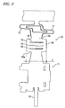
- FIGS. 3 to 5 a method for crimping the terminal fitting 10 will be described below referring to FIGS. 3 to 5 .
- the terminal fitting 10 to be crimped is set on a crimping machine (not shown)
- the bottom plate 18 of the terminal fitting 10 is placed on the upper face of an anvil 50
- the core wire 15 is placed on the bottom plate 18 as shown in FIG. 3 .
- a crimper 60 is provided above the anvil 50.
- the electric wire crimping section 12 is crimped by lowering the crimper 60 toward the anvil 50.
- the tip ends of both the wire barrel pieces 16 are bent so as to become close to each other along the crimping faces of the crimper 60, whereby the tip ends of both the wire barrel pieces 16 are made contact with each other.
- the element wires constituting the core wire 15 each maintain a circular cross-sectional shape, and clearances are formed among the element wires.
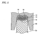
- the crimper 60 is lowered further from the state shown in FIG. 4 , the element wires constituting the core wire 15 are deformed and made close contact with one another in a state in which there is no clearance as shown in FIG.5 . Then, when the crimper 60 is raised and the terminal fitting 10 having been crimped is taken out, the terminal fitting 10 having the crimped shape shown in FIG. 6 is obtained.
- FIG. 9 is a graph representing the relationship between the height to width ratio of the electric wire crimping section 12 and the elongation ratio of the terminal fitting 10.
- TABLES 1 to 3 shown below provide data on which the graph of FIG. 9 is based.
- the values shown in the AVE. column of each table are plotted in the graph.
- the other experiment conditions are as described in the area enclosed by the rectangle shown in the lower portion of FIG. 9 .
- the developed length of the barrel in the experiment conditions shown in FIG. 9 is the dimension designated by L in FIG. 2 .
- the elongation ratios in the cases of compression ratios of 70% and 75% are smaller than those in the cases of compression ratios of 55% to 65%, since the contact resistance is likely to increase when the terminal fitting 10 is subjected to the thermal shock cycle, it is preferable that the compression ratio should be 55% or more and 65% or less.
- the embodiment produces an excellent effect capable of preventing the contact resistance from increasing even if the terminal fitting is subjected to the thermal shock cycle while the elongation ratio of the terminal fitting is suppressed small.
- the height to width ratio is set to 0.55 and that the compression ratio is set to 60%, an ideally crimped cross-sectional shape can be obtained.
Landscapes
- Engineering & Computer Science (AREA)
- Manufacturing & Machinery (AREA)
- Connections Effected By Soldering, Adhesion, Or Permanent Deformation (AREA)
- Manufacturing Of Electrical Connectors (AREA)
Claims (3)
- Un câble électrique serti avec une borne, comprenant :un câble électrique présentant un fil central ou encore fil noyau constitué d'aluminium ou d'un alliage d'aluminium ; etune garniture de borne présentant une section de sertissage de fil électrique pour sertir le fil central partiellement exposé du fil électrique, sachant que la valeur obtenue en divisant la superficie brute de section transversale du fil central après le sertissage de la section de sertissage de fil électrique par la superficie brute de section transversale du fil central avant le sertissage de la section de sertissage de fil électrique est appelée rapport de compression, et sachant que ledit rapport de compression est fixé à 55%,caractérisé en ce que
une valeur obtenue en divisant la hauteur de la section de sertissage de fil électrique par l'ampleur de la section de sertissage de fil électrique après le sertissage de la section de fil électrique est appelée rapport hauteur-largeur, et que ledit rapport hauteur-largeur est fixé à 0,53. - Le câble électrique serti avec la borne d'après la revendication 1, sachant que :la section de sertissage de fil électrique est équipée d'une paire de pièces en tonneau qui s'élèvent à partir des deux périphéries terminales de la plaque de fond de la garniture de borne ; et quel'extrémité de pointe d'une des pièces en tonneau est pliée vers l'autre pièce en tonneau et tournée vers la plaque de fond.
- Un procédé pour produire un câble électrique serti avec une borne, dans lequel une garniture de borne est raccordée par sertissage à une partie d'un fil électrique présentant un fil central ou encore fil noyau constitué d'aluminium ou d'un alliage d'aluminium, le procédé comprenant le fait de :placer le fil central sur la section de sertissage de fil électrique de la garniture de borne ; etcomprimer le fil central et la section de sertissage de fil électrique pour relier de façon conductrice le fil central à la section de sertissage de fil électrique en sertissant le fil central et la section de sertissage de fil électrique entre une paire de matrices (dies), sachant quela valeur obtenue en divisant la superficie brute de section transversale du fil central après le sertissage de la section de sertissage de fil électrique par la superficie brute de section transversale du fil central avant le sertissage de la section de sertissage de fil électrique est appelée rapport de compression, et sachant que ledit rapport de compression est fixé à 55%,caractérisé par le fait de
fixer un rapport hauteur-largeur à 0,53, sachant que
la valeur obtenue en divisant la hauteur (H1 à H3) de la section de sertissage de fil électrique (12) par l'ampleur (W1 à W3) de la section de sertissage de fil électrique (12) après le sertissage de la section de fil électrique (12) est ledit rapport hauteur-largeur.
Applications Claiming Priority (1)
| Application Number | Priority Date | Filing Date | Title |
|---|---|---|---|
| JP2009184426A JP2011040194A (ja) | 2009-08-07 | 2009-08-07 | 端子付き圧着電線および端子付き圧着電線の製造方法 |
Publications (2)
| Publication Number | Publication Date |
|---|---|
| EP2282373A1 EP2282373A1 (fr) | 2011-02-09 |
| EP2282373B1 true EP2282373B1 (fr) | 2016-11-02 |
Family
ID=42740409
Family Applications (1)
| Application Number | Title | Priority Date | Filing Date |
|---|---|---|---|
| EP10008298.1A Not-in-force EP2282373B1 (fr) | 2009-08-07 | 2010-08-09 | Câble électrique serti avec borne et son procédé de production |
Country Status (4)
| Country | Link |
|---|---|
| US (1) | US8628363B2 (fr) |
| EP (1) | EP2282373B1 (fr) |
| JP (1) | JP2011040194A (fr) |
| CN (1) | CN101997176A (fr) |
Families Citing this family (22)
| Publication number | Priority date | Publication date | Assignee | Title |
|---|---|---|---|---|
| JP2013054835A (ja) | 2011-09-01 | 2013-03-21 | Auto Network Gijutsu Kenkyusho:Kk | 端子金具、端子金具付き電線、および端子金具と電線の接続方法 |
| DE102011089207C5 (de) | 2011-12-20 | 2024-09-05 | Lisa Dräxlmaier GmbH | Verfahren zum Kontaktieren einer Litzenleitung mit einem Kontakt |
| CN103811879A (zh) * | 2012-11-09 | 2014-05-21 | 镇江宏联电工有限公司(中外合资) | 铝电抗器与铜引线焊接接头结构 |
| DE102013201167A1 (de) * | 2013-01-24 | 2014-08-07 | Elringklinger Ag | Verfahren zum Herstellen einer elektrisch leitenden Verbindung zwischen einer elektrischen Leitung und einem elektrisch leitenden Bauteil und nach dem Verfahren hergestellte Baugruppe |
| JP2014199721A (ja) | 2013-03-29 | 2014-10-23 | 日本碍子株式会社 | 圧着端子,圧着体及び圧着体の製造方法。 |
| US9391418B2 (en) * | 2013-08-13 | 2016-07-12 | Tyco Electronics Corporation | Terminal crimping device for determining a crimp height of a crimped electrical connection |
| US9362700B2 (en) * | 2013-08-13 | 2016-06-07 | Tyco Electronics Corporation | Device for determining a crimp height of a crimped electrical connection |
| JP6563168B2 (ja) * | 2013-11-25 | 2019-08-21 | 矢崎総業株式会社 | 圧着端子 |
| WO2015146819A1 (fr) * | 2014-03-24 | 2015-10-01 | 古河電気工業株式会社 | Faisceau de fils, procédé de connexion entre un fil conducteur revêtu et une borne, et corps de structure de faisceau de fils |
| JP6163149B2 (ja) * | 2014-12-15 | 2017-07-12 | 株式会社オートネットワーク技術研究所 | 端子付き電線の製造方法 |
| CN104538816A (zh) * | 2015-01-14 | 2015-04-22 | 合肥得润电子器件有限公司 | 一种端子压接及检验方法 |
| JP6154850B2 (ja) * | 2015-05-25 | 2017-06-28 | 日本碍子株式会社 | 圧着体及び圧着体の製造方法 |
| JP2017201577A (ja) * | 2016-05-02 | 2017-11-09 | 住友電装株式会社 | 端子付電線 |
| JP6434950B2 (ja) * | 2016-10-13 | 2018-12-05 | 矢崎総業株式会社 | 端子圧着装置 |
| JP6410163B1 (ja) * | 2017-06-22 | 2018-10-24 | 日立金属株式会社 | 端子付き電線 |
| JP6713009B2 (ja) * | 2018-02-15 | 2020-06-24 | 株式会社オートネットワーク技術研究所 | 端子、及びコネクタ |
| EP3588679B1 (fr) * | 2018-06-29 | 2023-09-27 | TE Connectivity Germany GmbH | Sertissage et procédé de production d'un sertissage |
| DE102019101017A1 (de) | 2019-01-16 | 2020-07-16 | Harting Electric Gmbh & Co. Kg | Verfahren und Vorrichtung zur Überwachung des Zustands einer Crimpeinrichtung |
| DE102019109460A1 (de) * | 2019-04-10 | 2020-10-15 | Te Connectivity Germany Gmbh | Crimpkontakt |
| CN111312439A (zh) * | 2020-04-01 | 2020-06-19 | 吉林省中赢高科技有限公司 | 一种电能传输铝件及其加工工艺 |
| CN112103746A (zh) * | 2020-08-10 | 2020-12-18 | 国网浙江省电力有限公司宁波供电公司 | 一种用于高压电缆头编织带与开口铜接头连接的压接装置 |
| CN216903370U (zh) * | 2022-03-24 | 2022-07-05 | 瑞智精密股份有限公司 | 压缩机电机漆包线的端子连接结构 |
Citations (3)
| Publication number | Priority date | Publication date | Assignee | Title |
|---|---|---|---|---|
| US3955044A (en) * | 1970-12-03 | 1976-05-04 | Amp Incorporated | Corrosion proof terminal for aluminum wire |
| JP2006286385A (ja) * | 2005-03-31 | 2006-10-19 | Asahi Electric Works Ltd | 端子金具と撚り線との圧着接続構造 |
| JP2009218072A (ja) * | 2008-03-10 | 2009-09-24 | Yazaki Corp | 圧着端子を用いた圧着方法、及び圧着端子を用いた圧着構造 |
Family Cites Families (19)
| Publication number | Priority date | Publication date | Assignee | Title |
|---|---|---|---|---|
| US2987697A (en) * | 1957-10-11 | 1961-06-06 | Ark Les Switch Corp | Electric connector |
| JPS63198268A (ja) * | 1987-02-12 | 1988-08-16 | 矢崎総業株式会社 | コネクタ端子の電線圧着構造 |
| JPH0522209A (ja) | 1991-07-10 | 1993-01-29 | Iwatsu Electric Co Ltd | 移動局接近報知システム |
| JPH0649361A (ja) | 1992-07-30 | 1994-02-22 | Mitsui Toatsu Chem Inc | ポリアミド酸水溶液 |
| JPH0680263A (ja) | 1992-09-01 | 1994-03-22 | Fuji Xerox Co Ltd | 画像形成装置の給紙装置 |
| JPH0680263U (ja) * | 1993-04-27 | 1994-11-08 | 矢崎総業株式会社 | 圧着端子 |
| JP2970362B2 (ja) | 1993-06-30 | 1999-11-02 | 住友電装株式会社 | 端子圧着構造及び端子圧着方法並びにこれらに用いる圧着端子 |
| US5561267A (en) | 1993-11-30 | 1996-10-01 | Sumitomo Wiring Systems, Ltd. | Crimp terminal and process for producing the same |
| EP1503454B1 (fr) * | 2003-07-30 | 2015-08-05 | Furukawa Electric Co. Ltd. | Assemblage de cosse sertie sur cable d'aluminium et méthode de fabrication |
| JP4809591B2 (ja) * | 2003-11-20 | 2011-11-09 | 古河電気工業株式会社 | アルミ電線への端子圧着構造及び端子圧着方法並びに端子付アルミ電線の製造方法 |
| JP2005327690A (ja) * | 2004-05-17 | 2005-11-24 | Furukawa Electric Co Ltd:The | アルミ電線への端子圧着構造及び端子圧着方法並びに端子付アルミ電線の製造方法 |
| JP4401877B2 (ja) | 2004-06-29 | 2010-01-20 | 株式会社オートネットワーク技術研究所 | コネクタ |
| FR2893193B1 (fr) * | 2005-11-09 | 2008-02-08 | Rh Innovation Sarl | Procede de sertissage |
| JP4550791B2 (ja) * | 2005-11-24 | 2010-09-22 | 古河電気工業株式会社 | アルミ撚線用圧着端子および前記圧着端子が接続されたアルミ撚線の端末構造 |
| JP2008177033A (ja) * | 2007-01-18 | 2008-07-31 | Yazaki Corp | 端子圧着装置 |
| JP4852436B2 (ja) * | 2007-01-23 | 2012-01-11 | 矢崎総業株式会社 | 銅合金線への端子圧着構造及び端子圧着方法、該端子圧着構造を備えたワイヤハーネス |
| JP5103137B2 (ja) * | 2007-11-01 | 2012-12-19 | 株式会社オートネットワーク技術研究所 | 圧着端子、端子付電線及びその製造方法 |
| JP5107693B2 (ja) * | 2007-12-21 | 2012-12-26 | タイコエレクトロニクスジャパン合同会社 | 圧着構造及び圧着方法 |
| JP2009272141A (ja) * | 2008-05-07 | 2009-11-19 | Autonetworks Technologies Ltd | 圧着端子及び端子付電線の製造方法 |
-
2009
- 2009-08-07 JP JP2009184426A patent/JP2011040194A/ja active Pending
-
2010
- 2010-08-09 US US12/852,815 patent/US8628363B2/en not_active Expired - Fee Related
- 2010-08-09 CN CN2010102511427A patent/CN101997176A/zh active Pending
- 2010-08-09 EP EP10008298.1A patent/EP2282373B1/fr not_active Not-in-force
Patent Citations (3)
| Publication number | Priority date | Publication date | Assignee | Title |
|---|---|---|---|---|
| US3955044A (en) * | 1970-12-03 | 1976-05-04 | Amp Incorporated | Corrosion proof terminal for aluminum wire |
| JP2006286385A (ja) * | 2005-03-31 | 2006-10-19 | Asahi Electric Works Ltd | 端子金具と撚り線との圧着接続構造 |
| JP2009218072A (ja) * | 2008-03-10 | 2009-09-24 | Yazaki Corp | 圧着端子を用いた圧着方法、及び圧着端子を用いた圧着構造 |
Also Published As
| Publication number | Publication date |
|---|---|
| EP2282373A1 (fr) | 2011-02-09 |
| US20110034091A1 (en) | 2011-02-10 |
| US8628363B2 (en) | 2014-01-14 |
| JP2011040194A (ja) | 2011-02-24 |
| CN101997176A (zh) | 2011-03-30 |
Similar Documents
| Publication | Publication Date | Title |
|---|---|---|
| EP2282373A1 (fr) | Câble électrique serti avec borne et son procédé de production | |
| US7494388B2 (en) | Terminal fitting having bi-metallic caulking pieces | |
| CN101842940B (zh) | 压接端子、带端子电线及带端子电线的制造方法 | |
| EP2472675B1 (fr) | Structure de sertissage de borne et procédé de sertissage de borne sur un fil électrique en aluminium | |
| KR101103114B1 (ko) | 압착 단자 피팅, 압착 단자 피팅의 제조 방법 및 단자 피팅을 구비한 전선 | |
| JP4376682B2 (ja) | 電線端部の加締構造 | |
| US8221171B2 (en) | Crimp terminal, terminal-provided wire, and manufacturing method thereof | |
| CN105229859B (zh) | 带端子电线 | |
| EP2765652B1 (fr) | Borne de type à sertir | |
| EP2602877B1 (fr) | Borne à sertir | |
| JP5080291B2 (ja) | 圧着端子、端子付電線及びその製造方法 | |
| US9048607B2 (en) | Terminal crimping apparatus, method of manufacturing terminal crimping electric wire, and terminal crimping electric wire | |
| EP2151892A1 (fr) | Pin de connection et méthode de connexion associée | |
| CN101536268A (zh) | 带有高导电性芯子的电端子 | |
| US20100055998A1 (en) | Terminal fitting and a wire connected with a terminal fitting | |
| US9088079B2 (en) | Crimped terminal attached electric wire and method of crimping crimped terminal to electric wire | |
| JP2010010086A (ja) | 端子金具及び端子付き電線 | |
| WO2013021602A1 (fr) | Fil à bornes serti | |
| JP7467516B2 (ja) | 圧着端子 | |
| US20130035008A1 (en) | Terminal fitting | |
| JP2010055902A (ja) | 端子金具および端子金具付き電線 |
Legal Events
| Date | Code | Title | Description |
|---|---|---|---|
| PUAI | Public reference made under article 153(3) epc to a published international application that has entered the european phase |
Free format text: ORIGINAL CODE: 0009012 |
|
| AK | Designated contracting states |
Kind code of ref document: A1 Designated state(s): AL AT BE BG CH CY CZ DE DK EE ES FI FR GB GR HR HU IE IS IT LI LT LU LV MC MK MT NL NO PL PT RO SE SI SK SM TR |
|
| AX | Request for extension of the european patent |
Extension state: BA ME RS |
|
| 17P | Request for examination filed |
Effective date: 20110324 |
|
| 17Q | First examination report despatched |
Effective date: 20110719 |
|
| RIC1 | Information provided on ipc code assigned before grant |
Ipc: H01R 4/62 20060101ALN20160421BHEP Ipc: H01R 4/20 20060101ALI20160421BHEP Ipc: H01R 43/048 20060101ALN20160421BHEP Ipc: H01R 4/18 20060101AFI20160421BHEP |
|
| RIC1 | Information provided on ipc code assigned before grant |
Ipc: H01R 4/62 20060101ALN20160422BHEP Ipc: H01R 4/18 20060101AFI20160422BHEP Ipc: H01R 43/048 20060101ALN20160422BHEP Ipc: H01R 4/20 20060101ALI20160422BHEP |
|
| GRAP | Despatch of communication of intention to grant a patent |
Free format text: ORIGINAL CODE: EPIDOSNIGR1 |
|
| INTG | Intention to grant announced |
Effective date: 20160610 |
|
| RIC1 | Information provided on ipc code assigned before grant |
Ipc: H01R 4/20 20060101ALI20160531BHEP Ipc: H01R 4/18 20060101AFI20160531BHEP Ipc: H01R 4/62 20060101ALN20160531BHEP Ipc: H01R 43/048 20060101ALN20160531BHEP |
|
| RIN1 | Information on inventor provided before grant (corrected) |
Inventor name: KOBAYASHI, KAZUMASA Inventor name: SHIMODA, HIROKI Inventor name: OOTSUKA, TAKUJI |
|
| RAP1 | Party data changed (applicant data changed or rights of an application transferred) |
Owner name: AUTONETWORKS TECHNOLOGIES, LTD. Owner name: SUMITOMO ELECTRIC INDUSTRIES, LTD. Owner name: SUMITOMO WIRING SYSTEMS, LTD. |
|
| GRAS | Grant fee paid |
Free format text: ORIGINAL CODE: EPIDOSNIGR3 |
|
| GRAA | (expected) grant |
Free format text: ORIGINAL CODE: 0009210 |
|
| AK | Designated contracting states |
Kind code of ref document: B1 Designated state(s): AL AT BE BG CH CY CZ DE DK EE ES FI FR GB GR HR HU IE IS IT LI LT LU LV MC MK MT NL NO PL PT RO SE SI SK SM TR |
|
| REG | Reference to a national code |
Ref country code: GB Ref legal event code: FG4D |
|
| REG | Reference to a national code |
Ref country code: AT Ref legal event code: REF Ref document number: 842684 Country of ref document: AT Kind code of ref document: T Effective date: 20161115 Ref country code: CH Ref legal event code: EP |
|
| REG | Reference to a national code |
Ref country code: IE Ref legal event code: FG4D |
|
| REG | Reference to a national code |
Ref country code: DE Ref legal event code: R096 Ref document number: 602010037568 Country of ref document: DE |
|
| PG25 | Lapsed in a contracting state [announced via postgrant information from national office to epo] |
Ref country code: LV Free format text: LAPSE BECAUSE OF FAILURE TO SUBMIT A TRANSLATION OF THE DESCRIPTION OR TO PAY THE FEE WITHIN THE PRESCRIBED TIME-LIMIT Effective date: 20161102 |
|
| REG | Reference to a national code |
Ref country code: NL Ref legal event code: MP Effective date: 20161102 |
|
| REG | Reference to a national code |
Ref country code: LT Ref legal event code: MG4D |
|
| REG | Reference to a national code |
Ref country code: AT Ref legal event code: MK05 Ref document number: 842684 Country of ref document: AT Kind code of ref document: T Effective date: 20161102 |
|
| PG25 | Lapsed in a contracting state [announced via postgrant information from national office to epo] |
Ref country code: GR Free format text: LAPSE BECAUSE OF FAILURE TO SUBMIT A TRANSLATION OF THE DESCRIPTION OR TO PAY THE FEE WITHIN THE PRESCRIBED TIME-LIMIT Effective date: 20170203 Ref country code: SE Free format text: LAPSE BECAUSE OF FAILURE TO SUBMIT A TRANSLATION OF THE DESCRIPTION OR TO PAY THE FEE WITHIN THE PRESCRIBED TIME-LIMIT Effective date: 20161102 Ref country code: NO Free format text: LAPSE BECAUSE OF FAILURE TO SUBMIT A TRANSLATION OF THE DESCRIPTION OR TO PAY THE FEE WITHIN THE PRESCRIBED TIME-LIMIT Effective date: 20170202 Ref country code: NL Free format text: LAPSE BECAUSE OF FAILURE TO SUBMIT A TRANSLATION OF THE DESCRIPTION OR TO PAY THE FEE WITHIN THE PRESCRIBED TIME-LIMIT Effective date: 20161102 Ref country code: LT Free format text: LAPSE BECAUSE OF FAILURE TO SUBMIT A TRANSLATION OF THE DESCRIPTION OR TO PAY THE FEE WITHIN THE PRESCRIBED TIME-LIMIT Effective date: 20161102 |
|
| PG25 | Lapsed in a contracting state [announced via postgrant information from national office to epo] |
Ref country code: PT Free format text: LAPSE BECAUSE OF FAILURE TO SUBMIT A TRANSLATION OF THE DESCRIPTION OR TO PAY THE FEE WITHIN THE PRESCRIBED TIME-LIMIT Effective date: 20170302 Ref country code: ES Free format text: LAPSE BECAUSE OF FAILURE TO SUBMIT A TRANSLATION OF THE DESCRIPTION OR TO PAY THE FEE WITHIN THE PRESCRIBED TIME-LIMIT Effective date: 20161102 Ref country code: AT Free format text: LAPSE BECAUSE OF FAILURE TO SUBMIT A TRANSLATION OF THE DESCRIPTION OR TO PAY THE FEE WITHIN THE PRESCRIBED TIME-LIMIT Effective date: 20161102 Ref country code: FI Free format text: LAPSE BECAUSE OF FAILURE TO SUBMIT A TRANSLATION OF THE DESCRIPTION OR TO PAY THE FEE WITHIN THE PRESCRIBED TIME-LIMIT Effective date: 20161102 Ref country code: HR Free format text: LAPSE BECAUSE OF FAILURE TO SUBMIT A TRANSLATION OF THE DESCRIPTION OR TO PAY THE FEE WITHIN THE PRESCRIBED TIME-LIMIT Effective date: 20161102 Ref country code: IS Free format text: LAPSE BECAUSE OF FAILURE TO SUBMIT A TRANSLATION OF THE DESCRIPTION OR TO PAY THE FEE WITHIN THE PRESCRIBED TIME-LIMIT Effective date: 20170302 Ref country code: PL Free format text: LAPSE BECAUSE OF FAILURE TO SUBMIT A TRANSLATION OF THE DESCRIPTION OR TO PAY THE FEE WITHIN THE PRESCRIBED TIME-LIMIT Effective date: 20161102 |
|
| PG25 | Lapsed in a contracting state [announced via postgrant information from national office to epo] |
Ref country code: DK Free format text: LAPSE BECAUSE OF FAILURE TO SUBMIT A TRANSLATION OF THE DESCRIPTION OR TO PAY THE FEE WITHIN THE PRESCRIBED TIME-LIMIT Effective date: 20161102 Ref country code: RO Free format text: LAPSE BECAUSE OF FAILURE TO SUBMIT A TRANSLATION OF THE DESCRIPTION OR TO PAY THE FEE WITHIN THE PRESCRIBED TIME-LIMIT Effective date: 20161102 Ref country code: CZ Free format text: LAPSE BECAUSE OF FAILURE TO SUBMIT A TRANSLATION OF THE DESCRIPTION OR TO PAY THE FEE WITHIN THE PRESCRIBED TIME-LIMIT Effective date: 20161102 Ref country code: SK Free format text: LAPSE BECAUSE OF FAILURE TO SUBMIT A TRANSLATION OF THE DESCRIPTION OR TO PAY THE FEE WITHIN THE PRESCRIBED TIME-LIMIT Effective date: 20161102 Ref country code: EE Free format text: LAPSE BECAUSE OF FAILURE TO SUBMIT A TRANSLATION OF THE DESCRIPTION OR TO PAY THE FEE WITHIN THE PRESCRIBED TIME-LIMIT Effective date: 20161102 |
|
| REG | Reference to a national code |
Ref country code: DE Ref legal event code: R097 Ref document number: 602010037568 Country of ref document: DE |
|
| PG25 | Lapsed in a contracting state [announced via postgrant information from national office to epo] |
Ref country code: BE Free format text: LAPSE BECAUSE OF FAILURE TO SUBMIT A TRANSLATION OF THE DESCRIPTION OR TO PAY THE FEE WITHIN THE PRESCRIBED TIME-LIMIT Effective date: 20161102 Ref country code: IT Free format text: LAPSE BECAUSE OF FAILURE TO SUBMIT A TRANSLATION OF THE DESCRIPTION OR TO PAY THE FEE WITHIN THE PRESCRIBED TIME-LIMIT Effective date: 20161102 Ref country code: BG Free format text: LAPSE BECAUSE OF FAILURE TO SUBMIT A TRANSLATION OF THE DESCRIPTION OR TO PAY THE FEE WITHIN THE PRESCRIBED TIME-LIMIT Effective date: 20170202 Ref country code: SM Free format text: LAPSE BECAUSE OF FAILURE TO SUBMIT A TRANSLATION OF THE DESCRIPTION OR TO PAY THE FEE WITHIN THE PRESCRIBED TIME-LIMIT Effective date: 20161102 |
|
| PLBE | No opposition filed within time limit |
Free format text: ORIGINAL CODE: 0009261 |
|
| STAA | Information on the status of an ep patent application or granted ep patent |
Free format text: STATUS: NO OPPOSITION FILED WITHIN TIME LIMIT |
|
| 26N | No opposition filed |
Effective date: 20170803 |
|
| PGFP | Annual fee paid to national office [announced via postgrant information from national office to epo] |
Ref country code: DE Payment date: 20170801 Year of fee payment: 8 |
|
| PG25 | Lapsed in a contracting state [announced via postgrant information from national office to epo] |
Ref country code: SI Free format text: LAPSE BECAUSE OF FAILURE TO SUBMIT A TRANSLATION OF THE DESCRIPTION OR TO PAY THE FEE WITHIN THE PRESCRIBED TIME-LIMIT Effective date: 20161102 |
|
| REG | Reference to a national code |
Ref country code: CH Ref legal event code: PL |
|
| PG25 | Lapsed in a contracting state [announced via postgrant information from national office to epo] |
Ref country code: MC Free format text: LAPSE BECAUSE OF FAILURE TO SUBMIT A TRANSLATION OF THE DESCRIPTION OR TO PAY THE FEE WITHIN THE PRESCRIBED TIME-LIMIT Effective date: 20161102 |
|
| GBPC | Gb: european patent ceased through non-payment of renewal fee |
Effective date: 20170809 |
|
| PG25 | Lapsed in a contracting state [announced via postgrant information from national office to epo] |
Ref country code: LI Free format text: LAPSE BECAUSE OF NON-PAYMENT OF DUE FEES Effective date: 20170831 Ref country code: CH Free format text: LAPSE BECAUSE OF NON-PAYMENT OF DUE FEES Effective date: 20170831 |
|
| REG | Reference to a national code |
Ref country code: FR Ref legal event code: ST Effective date: 20180430 |
|
| REG | Reference to a national code |
Ref country code: IE Ref legal event code: MM4A |
|
| PG25 | Lapsed in a contracting state [announced via postgrant information from national office to epo] |
Ref country code: LU Free format text: LAPSE BECAUSE OF NON-PAYMENT OF DUE FEES Effective date: 20170809 |
|
| PG25 | Lapsed in a contracting state [announced via postgrant information from national office to epo] |
Ref country code: IE Free format text: LAPSE BECAUSE OF NON-PAYMENT OF DUE FEES Effective date: 20170809 Ref country code: GB Free format text: LAPSE BECAUSE OF NON-PAYMENT OF DUE FEES Effective date: 20170809 |
|
| PG25 | Lapsed in a contracting state [announced via postgrant information from national office to epo] |
Ref country code: FR Free format text: LAPSE BECAUSE OF NON-PAYMENT OF DUE FEES Effective date: 20170831 |
|
| PG25 | Lapsed in a contracting state [announced via postgrant information from national office to epo] |
Ref country code: MT Free format text: LAPSE BECAUSE OF NON-PAYMENT OF DUE FEES Effective date: 20170809 |
|
| REG | Reference to a national code |
Ref country code: DE Ref legal event code: R119 Ref document number: 602010037568 Country of ref document: DE |
|
| PG25 | Lapsed in a contracting state [announced via postgrant information from national office to epo] |
Ref country code: HU Free format text: LAPSE BECAUSE OF FAILURE TO SUBMIT A TRANSLATION OF THE DESCRIPTION OR TO PAY THE FEE WITHIN THE PRESCRIBED TIME-LIMIT; INVALID AB INITIO Effective date: 20100809 |
|
| PG25 | Lapsed in a contracting state [announced via postgrant information from national office to epo] |
Ref country code: DE Free format text: LAPSE BECAUSE OF NON-PAYMENT OF DUE FEES Effective date: 20190301 |
|
| PG25 | Lapsed in a contracting state [announced via postgrant information from national office to epo] |
Ref country code: CY Free format text: LAPSE BECAUSE OF NON-PAYMENT OF DUE FEES Effective date: 20161102 |
|
| PG25 | Lapsed in a contracting state [announced via postgrant information from national office to epo] |
Ref country code: MK Free format text: LAPSE BECAUSE OF FAILURE TO SUBMIT A TRANSLATION OF THE DESCRIPTION OR TO PAY THE FEE WITHIN THE PRESCRIBED TIME-LIMIT Effective date: 20161102 |
|
| PG25 | Lapsed in a contracting state [announced via postgrant information from national office to epo] |
Ref country code: TR Free format text: LAPSE BECAUSE OF FAILURE TO SUBMIT A TRANSLATION OF THE DESCRIPTION OR TO PAY THE FEE WITHIN THE PRESCRIBED TIME-LIMIT Effective date: 20161102 |
|
| PG25 | Lapsed in a contracting state [announced via postgrant information from national office to epo] |
Ref country code: AL Free format text: LAPSE BECAUSE OF FAILURE TO SUBMIT A TRANSLATION OF THE DESCRIPTION OR TO PAY THE FEE WITHIN THE PRESCRIBED TIME-LIMIT Effective date: 20161102 |