EP2282429B1 - Funkkommunikationssystem - Google Patents
Funkkommunikationssystem Download PDFInfo
- Publication number
- EP2282429B1 EP2282429B1 EP09754659.2A EP09754659A EP2282429B1 EP 2282429 B1 EP2282429 B1 EP 2282429B1 EP 09754659 A EP09754659 A EP 09754659A EP 2282429 B1 EP2282429 B1 EP 2282429B1
- Authority
- EP
- European Patent Office
- Prior art keywords
- radio communication
- communication system
- sub
- carriers
- radio
- Prior art date
- Legal status (The legal status is an assumption and is not a legal conclusion. Google has not performed a legal analysis and makes no representation as to the accuracy of the status listed.)
- Not-in-force
Links
Images






Classifications
-
- H—ELECTRICITY
- H04—ELECTRIC COMMUNICATION TECHNIQUE
- H04L—TRANSMISSION OF DIGITAL INFORMATION, e.g. TELEGRAPHIC COMMUNICATION
- H04L5/00—Arrangements affording multiple use of the transmission path
- H04L5/003—Arrangements for allocating sub-channels of the transmission path
- H04L5/0058—Allocation criteria
- H04L5/0066—Requirements on out-of-channel emissions
-
- H—ELECTRICITY
- H04—ELECTRIC COMMUNICATION TECHNIQUE
- H04L—TRANSMISSION OF DIGITAL INFORMATION, e.g. TELEGRAPHIC COMMUNICATION
- H04L5/00—Arrangements affording multiple use of the transmission path
- H04L5/003—Arrangements for allocating sub-channels of the transmission path
- H04L5/0032—Distributed allocation, i.e. involving a plurality of allocating devices, each making partial allocation
-
- H—ELECTRICITY
- H04—ELECTRIC COMMUNICATION TECHNIQUE
- H04L—TRANSMISSION OF DIGITAL INFORMATION, e.g. TELEGRAPHIC COMMUNICATION
- H04L5/00—Arrangements affording multiple use of the transmission path
- H04L5/003—Arrangements for allocating sub-channels of the transmission path
- H04L5/0032—Distributed allocation, i.e. involving a plurality of allocating devices, each making partial allocation
- H04L5/0035—Resource allocation in a cooperative multipoint environment
-
- H—ELECTRICITY
- H04—ELECTRIC COMMUNICATION TECHNIQUE
- H04L—TRANSMISSION OF DIGITAL INFORMATION, e.g. TELEGRAPHIC COMMUNICATION
- H04L5/00—Arrangements affording multiple use of the transmission path
- H04L5/003—Arrangements for allocating sub-channels of the transmission path
- H04L5/0037—Inter-user or inter-terminal allocation
- H04L5/0041—Frequency-non-contiguous
-
- H—ELECTRICITY
- H04—ELECTRIC COMMUNICATION TECHNIQUE
- H04L—TRANSMISSION OF DIGITAL INFORMATION, e.g. TELEGRAPHIC COMMUNICATION
- H04L27/00—Modulated-carrier systems
- H04L27/26—Systems using multi-frequency codes
- H04L27/2601—Multicarrier modulation systems
- H04L27/2614—Peak power aspects
- H04L27/2623—Reduction thereof by clipping
-
- H—ELECTRICITY
- H04—ELECTRIC COMMUNICATION TECHNIQUE
- H04L—TRANSMISSION OF DIGITAL INFORMATION, e.g. TELEGRAPHIC COMMUNICATION
- H04L5/00—Arrangements affording multiple use of the transmission path
- H04L5/0001—Arrangements for dividing the transmission path
- H04L5/0003—Two-dimensional division
- H04L5/0005—Time-frequency
- H04L5/0007—Time-frequency the frequencies being orthogonal, e.g. OFDM(A) or DMT
-
- H—ELECTRICITY
- H04—ELECTRIC COMMUNICATION TECHNIQUE
- H04L—TRANSMISSION OF DIGITAL INFORMATION, e.g. TELEGRAPHIC COMMUNICATION
- H04L5/00—Arrangements affording multiple use of the transmission path
- H04L5/003—Arrangements for allocating sub-channels of the transmission path
- H04L5/0058—Allocation criteria
- H04L5/0064—Rate requirement of the data, e.g. scalable bandwidth, data priority
Definitions
- the present invention relates to a radio communication system including a first radio communication system configured to transmit and receive a radio signal by using multiple sub-carriers having a prescribed frequency spacing therebetween, and a second radio communication system configured to transmit and receive a radio signal in an adjacent frequency band by using multiple sub-carriers.
- the frequency response of a radio signal to be transmitted in each of the radio communication systems is used to define a spectrum mask for transmission power.
- the radio communication systems each control the amount of out -of -band radiation to a value not exceeding the spectrum mask, thereby avoiding inter-system interference.
- this method principally is a measure against intermodulation distortion on the transmission side. Hence, it is difficult to sufficiently suppress the influence of intermodulation distortion on the reception side with this method.
- defining too stringent spectrum mask results in an increase in the cost and size of devices constituting the radio communication systems, and is thus not favorable.
- Patent Literature 1 a method of dynamically controlling inter-system interference is known (see Patent Literature 1, for example). This method takes into consideration of the influence of a dominant wave used in data transmission on another radio communication system. Note that, this method does not refer to the influence of spurious emission on another radio communication system.
- EP 1 739 909 A1 relates to a method and an apparatus for reducing the interferences between a wide band device and a narrow band device interfering with said wide band device.
- Patent Literature 1 Japanese Patent Application Publication No. 2007-282228 (pp. 5-6)
- a high peak component sometimes occurs in transmission signals depending on a combination of the transmission signals. This often raises a problem of interference with another radio communication system due to the operation of a nonlinear device in its saturation region (spurious emission), the nonlinear device constituting a low-noise amplifier (LNA) or a mixer of a receiver.
- LNA low-noise amplifier
- the interference with another radio communication system presents a serious problem particularly when multiple noncontiguous frequency bands are used together instead of contiguous and wide frequency bands in order to achieve a fast communication speed.
- An objective of the present invention is to provide a radio communication system capable of effectively reducing interference with an adjacent radio communication system using an adjacent frequency band when employing a multi-carrier scheme.
- a radio communication system including a first radio communication system (radio communication system 100) configured to transmit and receive a radio signal (radio signal RS) in a prescribed frequency band (band BW1) by using a plurality of first sub-carriers (sub-carriers S1l) having a prescribed frequency spacing therebetween, and a second radio communication system (radio communication system 2) configured to transmit and receive a radio signal (radio signal RS) in an adjacent frequency band (band BW2) adjacent to the prescribed frequency band by using a plurality of second sub-carriers (sub-carriers S21), wherein the second radio communication system includes a sub-carrier selection unit (sub-carrier selection unit 303) configured to select one or more of the second sub-carriers to be used in accordance with a condition of the first sub-carriers, and a transmission unit (radio signal RS) in a prescribed frequency band (band BW1) by using a plurality of first sub-carriers (sub-carriers S1l) having a prescribed frequency
- the second sub-carriers located between the multiple first sub-carriers radiated in the adjacent frequency band are selected in accordance with the status of the first sub-carriers used by the first radio communication system.
- the second example relates to the first example and summarized in that the first radio communication system includes a used sub-carrier determining unit (sub-carrier processing unit 303) configured to use one or more of the first sub-carriers satisfying f+(NM+n) ⁇ f, where f represents a reference frequency in the prescribed frequency band, ⁇ f represents a spacing between the first sub-carriers, N and n each represent a certain natural number, and M represents an integer within such a range that f+(NM+n) ⁇ f falls within the prescribed frequency band, and the sub-carrier selection unit selects the second sub-carriers satisfying f+ (NM+m) ⁇ f, where m represents a positive integer other than n and smaller than N.
- a used sub-carrier determining unit sub-carrier processing unit 303 configured to use one or more of the first sub-carriers satisfying f+(NM+n) ⁇ f, where f represents a reference frequency in the prescribed frequency band, ⁇ f represents a spacing between the first sub-
- the third example relates to the second example and summarized in that the first radio communication system and the second radio communication system employ orthogonal frequency-division multiplexing.
- the fourth example relates to the third example and summarized in that a symbol (symbol SY) associated with a plurality of bits is used in the first radio communication system and the second radio communication system, and a timing for transmitting the symbol in the first radio communication system and a timing for transmitting the symbol in the second radio communication system are synchronized.
- a symbol symbol SY
- a timing for transmitting the symbol in the first radio communication system and a timing for transmitting the symbol in the second radio communication system are synchronized.
- the fifth example relates to the second example and summarized in that N satisfies N ⁇ 2, the sub-carrier selection unit selects sets of the second sub-carriers meeting a plurality of values of m, and the transmission unit transmits a radio signal by using the sets of second sub-carriers selected by the sub-carrier selection unit.
- the sixth example relates to the second example and summarized in that a transmission frame (transmission frame F) to be transmitted in the first radio communication system is divided into a plurality of time domains (time slots TS1 and TS2) along a time axis, and in each of the first radio communication system and the second radio communication system, the value of N is different for each of the time domains.
- transmission frame F transmission frame F
- the seventh example relates to the second example and summarized in that the first radio communication system includes a condition acquiring unit (network connecting unit 315 for example) configured to acquire an operating condition of the second radio communication system, and the used sub-carrier determining unit determines N on the basis of the operating condition acquired by the condition acquiring unit.
- a condition acquiring unit network connecting unit 315 for example
- the used sub-carrier determining unit determines N on the basis of the operating condition acquired by the condition acquiring unit.
- the eighth example relates to the seventh example and summarized in that the condition acquiring unit includes propagation loss between a transmitter and a receiver included in the second radio communication system.
- the ninth example relates to the seventh example and summarized in that the used sub-carrier determining unit determines N and n on the basis of a bandwidth of the prescribed frequency band used in the first radio communication system.
- the present invention is capable of providing a radio communication system effectively reducing interference with an adjacent radio communication system using an adjacent frequency band when employing a multi-carrier scheme.
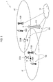
- Fig. 1 is a diagram showing a schematic configuration of an entire radio communication system 1 according to this embodiment.
- the radio communication system 1 includes a radio communication system 100 and a radio communication system 200.
- the radio communication system 100 includes radio base stations 110A and 110B and radio communication terminals 160A and 160B.
- the radio communication terminals 160A and 160B are mobile radio communication terminals.
- the radio communication system 100 is a mobile phone system, and constitutes a first radio communication system.
- the radio communication system 200 includes a transmitter station 210 and receivers 220A and 220B.
- the receivers 220A and 220B are placed in certain positions, and receive a radio signal RS transmitted from the transmitter station 210.
- the radio communication system 200 is a broadcast system, and constitutes a second radio communication system.
- the radio base stations 110A and 110B transmit radio signals RS toward the radio communication terminals 160A and 160B.
- the radio base station 110A forms a cover area A1
- the radio base station 110B forms a cover area A2.
- the radio communication system 100 is a multi-cell radio communication system including multiple cells (radio base stations).
- the radio communication system 100 and the radio communication system 200 employ orthogonal frequency-division multiplexing (OFDM).
- the radio communication system 100 and the radio communication system 200 are connected to each other via a communication network 10.
- Fig. 2 is an example showing how sub-carriers are arranged in a frequency band in which the radio communication system 100 performs transmission.
- the radio communication system 100 transmits and receives a radio signal RS in a band BW1 (prescribed frequency band) by using multiple sub-carriers S11 (first sub-carriers) having a prescribed frequency spacing therebetween.
- the radio communication system 200 transmits and receives a radio signal RS by using multiple sub-carriers S21 (second sub-carriers) in a band BW2 adjacent to the band BW1 (adjacent frequency band).
- a high peak component can occur in a time signal, more specifically, an output signal of an IFFT unit 305 (see Fig. 4 ), depending on combinations of transmitted symbols SY (unillustrated in Fig. 2 , see Fig. 4 ) .
- a nonlinear device constituting a radio unit 313 (see Fig. 4 ), such as a power amplifier
- this causes distortion (nonlinear distortion) of the signal, which in turn results in an increase in the amount of out-of-band radiation in the band BW2 adjacent to the band BW1.
- spurious waves are generated also at a frequency spacing ( ⁇ f) for all the sub-carriers S11 outside the band BW1, i.e., in the band BW2.
- the sub-carriers S11 are used at a spacing of two sub-carriers.
- spurious waves which are generated in the band BW2 by a signal with a spacing of two sub-carriers passing through the nonlinear device operating under saturation conditions, are generated also at a spacing of 2 ⁇ f.
- Fig. 3 is an example showing how sub-carriers are arranged with a spacing between sub-carriers of 2 ⁇ f. Assuming that the frequency of spurious waves (sub-carriers S11) generated by the radio communication system 100 is f+2n ⁇ f, the radio communication system 200 using the band BW2 performs communications by using sub-carriers S21 with a frequency of f+(2n+1) ⁇ f.
- f represents a reference frequency
- ⁇ f represents a spacing between sub-carriers
- n represents an integer which corresponds to sub-carriers in both of the bands (band BW1 and band BW2) and which falls within such a range that f+2n ⁇ f and f+(2n+1) ⁇ f fall within the respective frequency bands (band BW1 and band BW2).
- sub-carrier numbers to be used may be set to fixed values on the basis of the result of adjustment in the radio communication system 100 and the radio communication system 200.
- the radio communication terminals 160A and 160B constituting the radio communication system 100 may determine their usable sub-carriers, and numbers of the sub-carriers thus determined may be notified to the radio communication system 200.
- the radio communication system 200 (receivers 220A and 220B) may transmit a radio signal RS by using the set of (or part of the set of) sub-carriers thus notified.
- the radio communication system 100 and the radio communication system 200 use the same spacing between sub-carriers ( ⁇ f).
- the radio communication system 200 may perform single-carrier communication using a band equivalent to one sub-carrier.
- the timing for transmitting symbols SY in the first radio communication system 100 and the timing for transmitting the symbols SY in the second radio communication system 200 are synchronized.
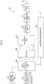
- Fig. 4 is a diagram showing the configuration of the functional blocks of the radio communication-device 300.
- the radio communication device 300 functions to transmit a radio signal RS.
- the radio communication device 300 includes a coding/symbol mapping unit 301, a sub-carrier processing unit 303, an IFFT unit 305, a P/S conversion unit 307, a GI adding unit 309, a D/A conversion unit 311, a radio unit 313, and a network connecting unit 315.
- the coding/symbol mapping unit 301 codes, with an error correction code, a transmission bit array transmitted.
- the coding/symbol mapping unit 301 also performs mapping to symbols SY each associated with multiple bits (for example, 0001).
- the sub-carrier processing unit 303 allocates sub-carriers to the symbols SY outputted from the coding/symbol mapping unit 301. In this embodiment, in particular, the sub-carrier processing unit 303 selects one or more sub-carriers S21 to be used in accordance with the status of the sub-carriers S11 used by the radio communication system 100 . When the radio communication device 300 is mounted in the transmitter station 210, the sub-carrier processing unit 303 constitutes a sub-carrier selection unit.
- the sub-carrier processing unit 303 selects sub-carriers S21 located between the multiple sub-carriers S11 radiated in the band BW2. In this embodiment, the sub-carrier processing unit 303 selects sub-carriers S21 satisfying f+(NM+m) ⁇ f.
- M represents an integer within such a range that f+(NM+n) ⁇ f to be described later falls within the band BW1.
- m represents a positive integer other than n and smaller than N.
- the IFFT unit 305 carries out inverse Fourier transform on the sub-carriers S21 outputted from the sub-carrier processing unit 303, and generates a time signal for the outputted sub-carriers S21.
- the P/S conversion unit 307 carries out parallel-serial conversion on the time signal outputted from the IFFT unit 305.
- the GI adding unit 309 adds a guard interval, more specifically part of the time signal.
- the D/A conversion unit 311 carries out digital/analog conversion on the time signal having the guard interval inserted thereto.
- the radio unit 313 carries out frequency conversion and power amplification on the signal outputted from the D/A conversion unit 311.
- the radio unit 313 also transmits, through an antenna, a radio signal RS generated by the execution of the frequency conversion and the power amplification.
- the radio unit 313 transmits the radio signal RS by using the sub-carriers S21 selected by the sub-carrier processing unit 303.
- the multiple sub-carriers S21 are transmitted in parallel, and each symbol SY is transmitted on any one of the sub-carriers S21.
- the radio unit 313 can transmit a radio signal RS using the selected sets of sub-carriers S21.
- the network connecting unit 315 provides a communication interface for connection with the communication network 10 (see Fig. 1 ).
- the network connecting unit 315 is connected to the sub-carrier processing unit 303, and transmits and receives, to and from the sub-carrier processing unit 303, information on the status of the sub-carriers being used by the radio communication system 100 and the radio communication system 200.
- the radio communication device 300 In the case where the radio communication device 300 is mounted in the radio base stations 110A and 110B, the radio communication device 300 provides functions to be described below. Note that, hereinbelow, description is given of parts different from the above case where the radio communication device 300 is mounted in the transmitter station 210.
- the sub-carriers S11 satisfy f+(NM+n) ⁇ f.
- f represents a reference frequency in the band BW1.
- N and n each represent a predetermined natural number.
- M represents an integer within such a range that f+(NM+n) ⁇ f falls within the band BW1.
- the sub-carrier processing unit 303 constitutes a used sub-carrier determining unit.
- the sub-carrier processing unit 303 determines N on the basis of the operating condition of the radio communication system 100 acquired by the network connecting unit 315. Alternatively, the sub-carrier processing unit 303 may determine N and n on the basis of the bandwidth of the band BW1 used by the radio communication system 100.
- the radio communication system 100 may determine N and m on the basis not of the operating condition of the radio communication system 200 but of a certain condition, e.g., to "select a set of N and m making the resource usage rate of each radio base station equal to or smaller than X%," according to the traffic state of the radio communication system 100.
- the radio communication system 200 may select a set of sub-carriers S21 to be used in accordance with the usage of the adjacent sub-carriers S11.
- the network connecting unit 315 acquires the operating condition of the radio communication system 200. To be more specific, the network connecting unit 315 acquires information on the usage of the sub-carriers S21, from the transmitter station 210 connected thereto via the communication network 10. The network connecting unit 315 notifies the sub-carrier processing unit 303 of the acquired information. When the radio communication device 300 is mounted in the radio base stations 110A and 110B, the network connecting unit 315 constitutes a condition acquiring unit.
- the network connecting unit 315 may also acquire information on propagation loss between the transmitter and each receiver included in the radio communication system 200, i.e., between the transmitter station 210 and each of the receivers 220A and 220B.
- the above embodiment has been given taking as an example the case where the amount of out-of-band radiation is constant independent of time, the radio base stations 110A and 110B, and the like. However, if there are no receivers 220A and 220B of the radio communication system 200, which use the band BW2 adjacent to the band BW1, in an area adjacent to the radio base stations 110A and 110B of the radio communication system 100, a larger amount of out-of-band radiation is allowed than in the case where such receivers exist in the area.
- the radio base stations 110A and 110B may control the amount of spurious waves to be transmitted outside the band, in accordance with the status of the radio communication system 200 using the band BW2.
- the radio base stations 110A and 110B use the sub-carriers S11 with a spacing of two sub-carriers being maintained between them, that is, with the number of sub-carriers to be used being reduced.
- the radio base stations 110A and 110B may use all the sub-carriers S11.
- the receivers 220A and 220B may notify the radio communication system 100 of the location information and operating condition of the receivers 220A and 220B.
- the receivers 220A and 220B may notify the radio communication system 100 not of the operating condition thereof but of the amount of interference caused by a radio signal RS transmitted from the transmitter station 210, the estimated propagation loss between the transmitter station 210 and each of the receivers 220A and 220B, and the amount of interference power reduction required.
- the estimated propagation loss may include the influence of the transmission antenna gain and the reception antenna gain.
- the allowable interference level which is set in accordance with the reception level of desired waves in the receivers 220A and 220B, may be notified together.
- the radio base stations 110A and 110B may determine N, m, and the transmission power so that the influence on the receivers 220A and 220B may be equal to or less than the allowable level.
- Fig. 5 shows the simulation result as to the status of sub-carriers in frequency bands.
- spurious waves of a relatively high level occur at all the frequency components in the band BW2 adjacent to the band BW1.
- AR1 in the drawing indicates SIR measured when the sub-carriers S11 are randomly used in the band BW1.
- the level of spurious waves is reduced at positions of sub-carriers used by the radio communication system 200 in the band BW2.
- AR2 in the drawing indicates SIR measured when the sub-carriers S11 and the sub-carriers S21 are used according to the method mentioned above.
- the interference by the sub-carriers S11 can be reduced in the radio communication system 200, which allows securing favorable reception quality.
- the method of sub-carrier allocation according to this embodiment is characterized by being advantageous in terms not only of the transmission spurious emission occurring on the transmission side but also of the reception intermodulation occurring on the reception side.
- the radio base stations 110A and 110B use different sub-carriers in the same frequency band, which allows reducing the inter-cell interference and effectively using large radio resources as a whole.
- the problem to be solved in this embodiment is likely to occur in the case where a receiver exists in a position adjacent to the radio base station 110A, like the receiver 220A does.
- the radio communication system 100 is deployed in a planar orientation like a multi-cell radio communication system, multiple radio base stations are generally not arranged adjacently. For this reason, the level at which the receiver 220A receives a radio signal RS transmitted from the radio base station 110B is relatively low. Accordingly, smaller spurious waves are generated due to the reception intermodulation, which rarely causes the generation of reception intermodulation large enough to disturb communication.
- the receiver 220B which receives radio signals RS transmitted from the radio base stations 110A and 110B at the same level, receives radio signals RS from the radio base stations 110A and 110B at a level lower than that of the receiver 220A.
- this embodiment also allows effectively reducing spurious waves generated due to the reception intermodulation.
- the radio communication system 200 selects sub-carriers S21 located between multiple sub-carriers S11 radiated in the band BW2 in accordance with the status of the sub-carriers S11 used by the radio communication system 100.
- the radio communication system 100 selects sub-carriers S11 satisfying f+(NM+n) ⁇ f; the radio communication system 200 selects sub-carriers S21 satisfying f+(NM+m) ⁇ f.
- m represents a positive integer other than n and smaller than N.
- the radio communication system 200 may determine a set of sub-carriers S21 which would not affect the radio communication system 100, in accordance with "the usage of the radio communication system 200" and "the influence of the radio communication system 100 on the radio communication system 200.”
- the interference between the radio communication system 100 and the radio communication system 200 using the band BW2 can be more effectively reduced even when the radiation of a radio signal RS in the band BW2 due to the operation of a nonlinear device in its saturation region occurs, that is, the out-of-band radiation occurs in the radio communication system 100.
- the timing for transmitting symbols SY in the radio communication system 100 and the timing for transmitting the symbols SY in the radio communication system 200 are synchronized. This suppresses the amount of out-of-band radiation due to the discontinuity of symbols SY. If symbols SY are operated asynchronously in the radio communication system 100 and the radio communication system 200, the sub-carrier allocation method described above is effective only in a situation where the amount of out-of-band radiation due to the distortion in a nonlinear device is larger than the amount of out-of-band radiation due to the discontinuity of symbols SY.
- the radio communication system 100 determines N on the basis of the operating condition of the radio communication system 200 acquired via the communication network 10. This allows more effectively using radio resources in the radio communication system 100 and the radio communication system 200 while suppressing the interference between the radio communication system 100 and the radio communication system 200 due to an increase in the amount of out-of-band radiation.
- Fig. 6 is an example showing how sub-carriers S11 are arranged in the band BW1 that the radio communication system 100 can use.
- the radio communication system 100 uses only sub-carriers S11 shown by the solid line out of the sub-carriers S11 shown in Fig. 6 .
- Fig. 7 shows an example of the sub-carriers S11 in the band BW1 and spurious waves caused by radiation of the sub-carriers S11 in the band BW2.
- the radio communication system 200 using the band BW2 uses one of sub-carrier arrangement patterns shown by the dotted line and the dashed-dotted line.
- the radio communication system 200 may use both the sub-carrier arrangement patterns shown by the dotted line and the dashed-dotted line.
- adjacent radio base stations use a single value as the above-mentioned spacing between sub-carriers, and that the adjacent radio base stations use different sub-carrier arrangement patterns.
- the use of such sub-carrier arrangement patterns allows preventing hindering the effective use of radio resources due to the presence of a sub-carrier not used at all in a specific area or the use of the same sub-carrier in adjacent radio base stations, for example.
- a spacing between sub-carriers S11 set in the radio communication system 100 may be shared via the communication network 10.
- the radio communication terminals 160A and 160B can measure the sub-carriers S11 used by the radio communication system 100, and notify the radio base stations 110A and 110B of the measurement result.
- the radio communication device 300 has only to include a reception processing unit 321 (see Fig. 1 ) which receives the measurement result notified from the radio base stations 110A and 110B.
- the radio base stations 110A and 110B may be set not to send radio signals RS when the radio communication terminals 160A and 160B measure the sub-carriers S11 used by the radio communication system 100 .
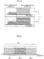
- Fig. 8 is an example showing how sub-carriers are arranged in the case where a transmission frame F is divided into time domains. As shown in Fig. 8 , the transmission frame F to be transmitted in the radio communication system 200 is divided into multiple time domains along the time axis, more specifically, into time slots TS1 and TS2.
- the radio communication system 200 may use sub-carriers which do not overlap spurious waves caused by out-of-band radiation from the radio communication system 100 (sub-carriers shown by the dotted line in Fig. 8 ).
- the value N (spacing between sub-carriers) described above is different for each time slot.
- the radio communication system 100 transmits all the sub-carriers in the time slot TS2. For this reason, spurious waves caused by out-of-band radiation from the radio communication system 100 exist in the band used by the radio communication system 200. Thus, the receivers 220A and 220B sometimes fail to receive radio signals RS transmitted by the transmitter station 210 properly.
- a receiver receiving large interference from the radio communication system 100 may use only sub-carriers shown by the dotted line in Fig. 8 .
- the sub-carriers shown by the dotted line in Fig. 8 may be allocated to a broadcast signal or a receiver receiving large interference from the radio communication system 100.
- sub-carriers shown by the solid line in Fig. 8 are preferably allocated to a receiver receiving small interference from the radio communication system 100.
- any one of (i) use of a value fixed in advance, (ii) determination based on the operating condition of the radio communication system 200, and (iii) determination based on the operating condition of the radio communication system 100, may be employed.
- the radio communication system 200 notifies the radio communication system 100 of the operating condition.
- a combination of the length of time slots and a sub-carrier arrangement pattern may be changed on the basis of the above operating condition.
- the frequency band that the radio communication system 1 can use is divided into multiple consecutive bands (sub-bands).
- the sub-carrier allocation described above is carried out on a specific sub-band.
- Fig. 9 is an example showing how sub-carriers are arranged in the case where the band BW1 is divided into sub-bands BW11 to BW13.
- the sub-carrier allocation is carried out so that the spacing of multiple sub-carriers (N sub-carriers) described above may be reserved only in the sub-bands located at outer sides among the sub-bands BW11 to BW13, i.e., the sub-band BW11 and the sub-band BW13 .
- the spacing of multiple sub-carriers is not reserved. Instead, all the sub-carriers may be used, or specific sub-carriers may be used in a pseudo-random manner.
- the radio communication system 200 and the radio communication system 100 employ OFDM. For this reason, in a mobile communication system such as the radio communication system 100, there are cases where signals are transmitted to multiple users (radio communication terminals) in the downlink by using the same symbol SY, and where the multiple users transmit signals by using the same symbol SY.
- Figs. 10(a) to 10(c) are an example showing how sub-carriers allocated to each user are arranged.
- a user 1 is assigned sub-carriers based on a sub-carrier pattern P1 (see Fig. 10 (b) )
- a user 2 is assigned sub-carriers based on a sub-carrier pattern P2 (see Fig. 10(c) ).
- the sub-carrier patterns P1 and P2 can be determined on the basis of sub-carriers selected in a pseudo-random manner or of a certain number of consecutive sub-carriers.
- clipping and filtering is known as a method of reducing the level of peak parts generated in a transmission radio signal. According to the clipping and filtering, clipping noise is generated by the clipping of peak parts of an OFDM signal.
- the following method is conventionally known as a method of controlling clipping noise in a frequency region.
- Fig. 11 is a diagram showing the configuration of functional blocks of a radio communication device 300A according to this embodiment.
- the radio communication device 300A includes a clipping unit 331, a FFT unit 333, and a filtering unit 335, as compared with the radio communication device 300 described above.
- the clipping unit 331 carries out clipping processing on an OFDM signal outputted from the IFFT unit 305.
- the clipping unit 331 carries out the clipping of peak parts of an OFDM signal outputted from the IFFT unit 305, on the basis of a publicly-known method of clipping processing (for example, " Effects of clipping and filtering on the performance of OFDM, " IEEE Commun. Lett. , vol. 2, No. 5, pp. 131 - 133, May 1998 ) .
- the FFT unit 333 carries out Fourier transform on the signal outputted from the clipping unit 331.
- the filtering unit 335 carries out filtering on clipping noise included in the signal outputted from the FFT unit 333.
- This embodiment limits sub-carriers, which are not used within the frequency band and which clipping noise overlaps with, to sub-carriers satisfying the following condition.
- sub-carriers to be used are limited to those satisfying f + NM + n ⁇ ⁇ f ,
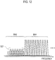
- Fig. 12 is an example showing how sub-carriers are allocated in the case where clipping noise overlaps with the sub-carriers.
- the control can be made such that clipping noise may overlap with only the sub-carriers shown by the dashed-dotted line. This prevents large interference on the sub-carriers S21 used by the radio communication system 200.
- the use of the sub-carriers not satisfying the above condition results in an increase in the level of spurious waves for the sub-carriers used by the radio communication system 200 in the band BW2 adjacent to the band BW1, depending on the dynamic range of the nonlinear device and the size of peak parts to be inputted.
- the level of allowable clipping noise may be estimated in advance, and clipping noise may be allowed up to this level.
- the radio communication system 100 and the radio communication system 200 have employed OFDM.
- the radio communication system 100 and the radio communication system 200 do not necessarily have to employ OFDM, but have only to employ multiple sub-carriers.
- parameters such as a spacing between sub-carriers and transmission power to be used may be determined in consideration not only of the radio communication systems using the adjacent frequency bands but also of radio communication systems using frequency bands other than the adjacent frequency bands (for example, frequency bands adjacent to the adjacent frequency bands).
- the above sub-carrier allocation method may be applied to both cases where adjacent frequency bands are used by different operators and where the adjacent frequency bands are used by a single operator.
- the frequency bands may be ones exclusively licensed to a specific operator, or may be ones requiring no license such as ones used by a short-distance radio communication system including a radio LAN system.
- the transmitter station 210 of the radio communication system 200 may perform both power control of a radio signal RS to be transmitted and a guard band adjustment, in order to reduce leakage power to an adjacent frequency band.
- the above third embodiment has been described taking as an example the case where a sub-carrier usage pattern is changed on a per time-domain basis .
- the number of multiple time-domains divided along the time axis (time slots TS) may be three or more, and the usage rate may be zero in part of the time-domains.
- a broadcast signal such as a control signal may be transmitted during the time with a usage rate of zero.
- the radio communication system 100 and the radio communication system 200 are not limited to such systems.
- the radio communication system 200 may be a satellite communication system or a radio LAN system.
- the first embodiment and the like have been described on the assumption that the radio communication system 100 is a multi-cell radio communication system including multiple cells, the radio communication system 100 may be a single-cell radio communication system.
- the present invention includes various embodiments and the like which are not described herein, as a matter of course. Therefore, a technological scope of the present invention is defined only by items specific to the invention according to claims pertinent based on the foregoing description.
- the radio communication system according to the present invention is capable of effectively reducing interference with an adjacent radio communication system using an adjacent frequency band when employing a multi-carrier scheme.
- the radio communication system is thus advantageous in radio communication such as mobile communication.
Landscapes
- Engineering & Computer Science (AREA)
- Signal Processing (AREA)
- Computer Networks & Wireless Communication (AREA)
- Mobile Radio Communication Systems (AREA)
Claims (9)
- Funkkommunikationssystem, umfassend:ein erstes Funkkommunikationssystem (100), das konfiguriert ist, ein Funksignal (RS) in einem vorgeschriebenen Frequenzband (BW1) mithilfe einer Vielzahl erster Unterträger (S11) mit einem vorgeschriebenen Frequenzabstand dazwischen zu senden und zu empfangen; undein zweites Funkkommunikationssystem (200), das konfiguriert ist, ein Funksignal (RS) in einem benachbarten Frequenzband (BW2), das zu dem vorgeschriebenen Frequenzband benachbart ist, mithilfe einer Vielzahl zweiter Unterträger (S21) zu senden und zu empfangen, wobeidas zweite Funkkommunikationssystem (200) aufweisteine Unterträgerauswahleinheit (303), die konfiguriert ist, einen oder mehrere der zu verwendenden zweiten Unterträger (S21) auszuwählen, undeine Sendeeinheit (313), die konfiguriert ist, ein Funksignal mithilfe der durch die Unterträgerauswahleinheit (303) ausgewählten zweiten Unterträger (S21) zu senden, wobei das Funkkommunikationssystem dadurch gekennzeichnet ist, dass:die Unterträgerauswahleinheit (303) konfiguriert ist, die zweiten Unterträger (S21) auszuwählen, die sich zwischen einer Vielzahl von Störwellen befinden, die in dem benachbarten Frequenzband (BW2) durch die Vielzahl von ersten Unterträgern (S11) erzeugt werden, wobei diese Störwellen zwischen sich ebenfalls den Frequenzabstand aufweisen.
- Funkkommunikationssystem nach Anspruch 1, wobei
das erste Funkkommunikationssystem (100) eine Einheit zum Bestimmen verwendeter Unterträger aufweist, die konfiguriert ist, einen oder mehrere der ersten Unterträger (S11) zu verwenden, für die gilt wobei f für eine Referenzfrequenz in dem vorgeschriebenen Frequenzband steht, Δf für einen Abstand zwischen den ersten Unterträgern (S11) steht,N und n für je eine bestimmte natürliche Zahl stehen undM für eine ganze Zahl in einem Bereich steht, sodass f + (NM + n) x Δf in das vorgeschriebene Frequenzband fällt,und die Unterträgerauswahleinheit (303) konfiguriert ist, die zweiten Unterträger (S21) auszuwählen, für die gilt
- Funkkommunikationssystem nach Anspruch 2, wobei
das erste Funkkommunikationssystem (100) und das zweite Funkkommunikationssystem (200) konfiguriert sind, ein orthogonales Frequenzmultiplexverfahren einzusetzen. - Funkkommunikationssystem nach Anspruch 3, wobei
im ersten Funkkommunikationssystem (100) und im zweiten Funkkommunikationssystem (200) ein Symbol verwendet wird, das einer Vielzahl von Bits zugeordnet ist, und
ein Timing zum Senden des Symbols im ersten Funkkommunikationssystem (100) und ein Timing zum Senden des Symbols im zweiten Funkkommunikationssystem (200) synchronisiert sind. - Funkkommunikationssystem nach Anspruch 2, wobei
für N gilt N ≥ 2,
die Unterträgerauswahleinheit (303) konfiguriert ist, Gruppen der zweiten Unterträger (S21) auszuwählen, die einer Vielzahl von Werten für m entsprechen, und
die Sendeeinheit (313) konfiguriert ist, ein Funksignal mithilfe der durch die Unterträgerauswahleinheit (303) ausgewählten Gruppen von zweiten Unterträgern (S21) zu senden. - Funkkommunikationssystem nach Anspruch 2, wobei
ein im ersten Funkkommunikationssystem (100) zu sendender Sendeframe in eine Vielzahl von Zeitbereichen entlang einer Zeitachse unterteilt wird und
in jedem von erstem Funkkommunikationssystem (100) und zweitem Funkkommunikationssystem (200) der Wert für N für jeden der Zeitbereiche anders ist. - Funkkommunikationssystem nach Anspruch 2, wobei
das erste Funkkommunikationssystem (100) eine Bedingungserfassungseinheit aufweist, die konfiguriert ist, eine Betriebsbedingung des zweiten Funkkommunikationssystems (200) zu erfassen, und
die Einheit zum Bestimmen verwendeter Unterträger konfiguriert ist, N auf Basis der durch die Bedingungserfassungseinheit erfassten Betriebsbedingung zu bestimmen. - Funkkommunikationssystem nach Anspruch 7, wobei die Bedingungserfassungseinheit Ausbreitungsverlust zwischen einem Transmitter und einem Empfänger aufweist, die das zweite Funkkommunikationssystem (200) aufweist.
- Funkkommunikationssystem nach Anspruch 2, wobei die Einheit zum Bestimmen verwendeter Unterträger konfiguriert ist, N und n auf Basis einer Bandbreite des in dem ersten Funkkommunikationssystem (100) verwendeten vorgeschriebenen Frequenzbands zu bestimmen.
Applications Claiming Priority (2)
| Application Number | Priority Date | Filing Date | Title |
|---|---|---|---|
| JP2008140193A JP5156485B2 (ja) | 2008-05-28 | 2008-05-28 | 無線通信システム |
| PCT/JP2009/059541 WO2009145151A1 (ja) | 2008-05-28 | 2009-05-25 | 無線通信システム |
Publications (3)
| Publication Number | Publication Date |
|---|---|
| EP2282429A1 EP2282429A1 (de) | 2011-02-09 |
| EP2282429A4 EP2282429A4 (de) | 2016-05-18 |
| EP2282429B1 true EP2282429B1 (de) | 2018-02-28 |
Family
ID=41377024
Family Applications (1)
| Application Number | Title | Priority Date | Filing Date |
|---|---|---|---|
| EP09754659.2A Not-in-force EP2282429B1 (de) | 2008-05-28 | 2009-05-25 | Funkkommunikationssystem |
Country Status (5)
| Country | Link |
|---|---|
| US (1) | US8619885B2 (de) |
| EP (1) | EP2282429B1 (de) |
| JP (1) | JP5156485B2 (de) |
| CN (1) | CN102047597B (de) |
| WO (1) | WO2009145151A1 (de) |
Families Citing this family (7)
| Publication number | Priority date | Publication date | Assignee | Title |
|---|---|---|---|---|
| BRPI0817599B1 (pt) * | 2007-10-04 | 2020-10-20 | Apple Inc | método e sistema para reduzir de forma adaptável uma razão de potência de pico para potência média em uma estação móvel |
| CN102783077A (zh) | 2010-01-12 | 2012-11-14 | 诺基亚西门子通信公司 | 基于发射接收频隙带在载波聚合通信系统中调度的设备和方法 |
| US9838137B2 (en) | 2015-12-18 | 2017-12-05 | Fujitsu Limited | Device and method for transmitting optical signal in which a plurality of signals are multiplexed |
| CN110289941B (zh) * | 2016-03-16 | 2022-06-28 | 华为技术有限公司 | 数据发送方法、数据接收方法、发送端设备及接收端设备 |
| EP3534656B1 (de) * | 2016-10-28 | 2022-06-22 | Ntt Docomo, Inc. | Benutzerendgerät und drahtloskommunikationsverfahren |
| CN108377555B (zh) * | 2017-01-31 | 2020-09-01 | 上海朗帛通信技术有限公司 | 一种用于无线通信中的用户设备、基站中的方法和装置 |
| FR3088795A1 (fr) * | 2018-11-19 | 2020-05-22 | Orange | Procédé de mise à disposition d’un deuxième opérateur d’une ressource d’accès gérée par un premier opérateur |
Family Cites Families (14)
| Publication number | Priority date | Publication date | Assignee | Title |
|---|---|---|---|---|
| JPS5698957A (en) * | 1980-01-11 | 1981-08-08 | Mitsubishi Electric Corp | Spectral diffusion communication system |
| JPH07273733A (ja) * | 1994-03-31 | 1995-10-20 | Toshiba Corp | 信号多重方法、多重信号送信装置及び多重信号受信装置 |
| DE19616829C1 (de) * | 1996-04-26 | 1997-04-24 | Siemens Ag | System zur Funkübertragung digitaler Signale zwischen mehreren Teilnehmerstationen und einer Basisstation |
| JP2920131B1 (ja) * | 1998-01-28 | 1999-07-19 | 株式会社次世代デジタルテレビジョン放送システム研究所 | Ofdm信号送出装置 |
| JP2000269917A (ja) * | 1999-03-12 | 2000-09-29 | Sony Corp | 送信装置および方法、並びに提供媒体 |
| US7012912B2 (en) * | 2003-05-14 | 2006-03-14 | Qualcomm Incorporated | Power control and scheduling in an OFDM system |
| KR100713528B1 (ko) * | 2004-03-12 | 2007-05-02 | 삼성전자주식회사 | 직교 주파수 분할 다중 접속 방식을 사용하는 통신시스템에서 서브 채널 신호 송신 장치 및 방법 |
| WO2006077696A1 (ja) * | 2005-01-18 | 2006-07-27 | Sharp Kabushiki Kaisha | 無線通信装置、携帯端末および無線通信方法 |
| US8144658B2 (en) * | 2005-02-11 | 2012-03-27 | Qualcomm Incorporated | Method and apparatus for mitigating interference in a wireless communication system |
| JP2006287624A (ja) * | 2005-03-31 | 2006-10-19 | Sanyo Electric Co Ltd | 無線基地局、通信チャネル割当方法及び通信チャネル割当処理用プログラム |
| EP1739909A1 (de) * | 2005-06-30 | 2007-01-03 | STMicroelectronics N.V. | Verfahren und Einrichtung zur Reduzierung der Interferenzen zwischen einem breitbandigen Gerät und einem störenden schmalbandigen Gerät |
| GB2436911B (en) | 2006-04-03 | 2010-10-20 | Toshiba Res Europ Ltd | Dynamic optimisation of block transmissions for interference avoidance |
| JP4893278B2 (ja) | 2006-12-01 | 2012-03-07 | 日本電気株式会社 | 証紙識別システム及び証紙識別方法 |
| JP2008177842A (ja) * | 2007-01-18 | 2008-07-31 | Mitsubishi Electric Corp | 受信装置、送信装置および通信システム |
-
2008
- 2008-05-28 JP JP2008140193A patent/JP5156485B2/ja not_active Expired - Fee Related
-
2009
- 2009-05-25 US US12/994,981 patent/US8619885B2/en not_active Expired - Fee Related
- 2009-05-25 EP EP09754659.2A patent/EP2282429B1/de not_active Not-in-force
- 2009-05-25 WO PCT/JP2009/059541 patent/WO2009145151A1/ja not_active Ceased
- 2009-05-25 CN CN2009801195521A patent/CN102047597B/zh not_active Expired - Fee Related
Non-Patent Citations (1)
| Title |
|---|
| None * |
Also Published As
| Publication number | Publication date |
|---|---|
| JP5156485B2 (ja) | 2013-03-06 |
| EP2282429A1 (de) | 2011-02-09 |
| WO2009145151A1 (ja) | 2009-12-03 |
| EP2282429A4 (de) | 2016-05-18 |
| CN102047597B (zh) | 2013-11-13 |
| US20110182377A1 (en) | 2011-07-28 |
| JP2009290493A (ja) | 2009-12-10 |
| CN102047597A (zh) | 2011-05-04 |
| US8619885B2 (en) | 2013-12-31 |
Similar Documents
| Publication | Publication Date | Title |
|---|---|---|
| CN101087290B (zh) | 发送器和发送方法 | |
| US7372909B2 (en) | Radio transmitting apparatus, radio receiving apparatus and method therefor | |
| EP2282429B1 (de) | Funkkommunikationssystem | |
| EP3254424B1 (de) | Anpassung des unterträgerfrequenzabstandes je nach energieeffizienzindikator | |
| Kryszkiewicz et al. | Protection of primary users in dynamically varying radio environment: practical solutions and challenges | |
| EP1039683A3 (de) | Frequenzsprungmehrfachzugriff mit Mehrträgersignalen | |
| KR101239580B1 (ko) | 기지국 장치, 이동국 장치, 블록 배치 방법, 데이터 수신 방법 및 집적 회로 | |
| CN103491047B (zh) | 发射端、接收端及单载波系统和多载波系统的共存方法 | |
| WO2007127009A2 (en) | Method, apparatus, and computer-readable medium for asymmetric frequency division duplexing operation | |
| US20020118783A1 (en) | Smart antenna based spectrum multiplexing using a pilot signal | |
| JP5606436B2 (ja) | 送信電力制御方法および送信装置 | |
| Mizutani et al. | Comprehensive performance evaluation of universal time-domain windowed OFDM-based LTE downlink system | |
| CN107371383B (zh) | 用于使用频谱掩模填充来降低无线通信系统中的峰均功率的方法和设备 | |
| EP1897313B1 (de) | Verfahren und Vorrichtung zum verringern der Störungen zwischen einer Breitbandeinrichtung und einer die Breitbandeinrichtung störenden Schmalband-Einrichtung | |
| EP1897312B1 (de) | Verfahren und Vorrichtung zum verringern der Störungen zwischen einer Breitbandeinrichtung und einem Schmalband-Störer | |
| US8570910B2 (en) | Wireless transmission apparatus and wireless transmission method | |
| Kiayani et al. | Linearity challenges of LTE-advanced mobile transmitters: Requirements and potential solutions | |
| EP2086154A1 (de) | Verfahren und Vorrichtung für Wellenlängenmultiplex-Zugriff mit lokalisiertem Frequenzsprung und leistungseffizientes Wellenlängenmultiplexen | |
| CN117119606A (zh) | 通信方法及装置、存储介质 | |
| JP2010199923A (ja) | 無線通信装置 | |
| Takakusaki et al. | Implementation of experimental equipment with Wideband Non-Contiguous OFDM | |
| JP2007243236A (ja) | 無線通信システム、無線通信装置及び無線通信方法、並びにコンピュータ・プログラム | |
| CN102077632A (zh) | 使用连续波频调的发射机覆盖标识 | |
| Kosaka et al. | Evaluation of influence by simultaneous reception of other radio systems in wideband NC-OFDM |
Legal Events
| Date | Code | Title | Description |
|---|---|---|---|
| PUAI | Public reference made under article 153(3) epc to a published international application that has entered the european phase |
Free format text: ORIGINAL CODE: 0009012 |
|
| 17P | Request for examination filed |
Effective date: 20101208 |
|
| AK | Designated contracting states |
Kind code of ref document: A1 Designated state(s): AT BE BG CH CY CZ DE DK EE ES FI FR GB GR HR HU IE IS IT LI LT LU LV MC MK MT NL NO PL PT RO SE SI SK TR |
|
| AX | Request for extension of the european patent |
Extension state: AL BA RS |
|
| DAX | Request for extension of the european patent (deleted) | ||
| RA4 | Supplementary search report drawn up and despatched (corrected) |
Effective date: 20160415 |
|
| RIC1 | Information provided on ipc code assigned before grant |
Ipc: H04J 11/00 20060101AFI20160411BHEP |
|
| GRAP | Despatch of communication of intention to grant a patent |
Free format text: ORIGINAL CODE: EPIDOSNIGR1 |
|
| INTG | Intention to grant announced |
Effective date: 20171106 |
|
| GRAS | Grant fee paid |
Free format text: ORIGINAL CODE: EPIDOSNIGR3 |
|
| GRAA | (expected) grant |
Free format text: ORIGINAL CODE: 0009210 |
|
| AK | Designated contracting states |
Kind code of ref document: B1 Designated state(s): AT BE BG CH CY CZ DE DK EE ES FI FR GB GR HR HU IE IS IT LI LT LU LV MC MK MT NL NO PL PT RO SE SI SK TR |
|
| REG | Reference to a national code |
Ref country code: GB Ref legal event code: FG4D Ref country code: CH Ref legal event code: EP |
|
| REG | Reference to a national code |
Ref country code: AT Ref legal event code: REF Ref document number: 975229 Country of ref document: AT Kind code of ref document: T Effective date: 20180315 |
|
| REG | Reference to a national code |
Ref country code: IE Ref legal event code: FG4D |
|
| REG | Reference to a national code |
Ref country code: DE Ref legal event code: R096 Ref document number: 602009050988 Country of ref document: DE |
|
| REG | Reference to a national code |
Ref country code: NL Ref legal event code: MP Effective date: 20180228 |
|
| REG | Reference to a national code |
Ref country code: LT Ref legal event code: MG4D |
|
| REG | Reference to a national code |
Ref country code: AT Ref legal event code: MK05 Ref document number: 975229 Country of ref document: AT Kind code of ref document: T Effective date: 20180228 |
|
| PG25 | Lapsed in a contracting state [announced via postgrant information from national office to epo] |
Ref country code: NO Free format text: LAPSE BECAUSE OF FAILURE TO SUBMIT A TRANSLATION OF THE DESCRIPTION OR TO PAY THE FEE WITHIN THE PRESCRIBED TIME-LIMIT Effective date: 20180528 Ref country code: CY Free format text: LAPSE BECAUSE OF FAILURE TO SUBMIT A TRANSLATION OF THE DESCRIPTION OR TO PAY THE FEE WITHIN THE PRESCRIBED TIME-LIMIT Effective date: 20180228 Ref country code: HR Free format text: LAPSE BECAUSE OF FAILURE TO SUBMIT A TRANSLATION OF THE DESCRIPTION OR TO PAY THE FEE WITHIN THE PRESCRIBED TIME-LIMIT Effective date: 20180228 Ref country code: ES Free format text: LAPSE BECAUSE OF FAILURE TO SUBMIT A TRANSLATION OF THE DESCRIPTION OR TO PAY THE FEE WITHIN THE PRESCRIBED TIME-LIMIT Effective date: 20180228 Ref country code: NL Free format text: LAPSE BECAUSE OF FAILURE TO SUBMIT A TRANSLATION OF THE DESCRIPTION OR TO PAY THE FEE WITHIN THE PRESCRIBED TIME-LIMIT Effective date: 20180228 Ref country code: LT Free format text: LAPSE BECAUSE OF FAILURE TO SUBMIT A TRANSLATION OF THE DESCRIPTION OR TO PAY THE FEE WITHIN THE PRESCRIBED TIME-LIMIT Effective date: 20180228 Ref country code: FI Free format text: LAPSE BECAUSE OF FAILURE TO SUBMIT A TRANSLATION OF THE DESCRIPTION OR TO PAY THE FEE WITHIN THE PRESCRIBED TIME-LIMIT Effective date: 20180228 |
|
| PG25 | Lapsed in a contracting state [announced via postgrant information from national office to epo] |
Ref country code: SE Free format text: LAPSE BECAUSE OF FAILURE TO SUBMIT A TRANSLATION OF THE DESCRIPTION OR TO PAY THE FEE WITHIN THE PRESCRIBED TIME-LIMIT Effective date: 20180228 Ref country code: LV Free format text: LAPSE BECAUSE OF FAILURE TO SUBMIT A TRANSLATION OF THE DESCRIPTION OR TO PAY THE FEE WITHIN THE PRESCRIBED TIME-LIMIT Effective date: 20180228 Ref country code: AT Free format text: LAPSE BECAUSE OF FAILURE TO SUBMIT A TRANSLATION OF THE DESCRIPTION OR TO PAY THE FEE WITHIN THE PRESCRIBED TIME-LIMIT Effective date: 20180228 Ref country code: GR Free format text: LAPSE BECAUSE OF FAILURE TO SUBMIT A TRANSLATION OF THE DESCRIPTION OR TO PAY THE FEE WITHIN THE PRESCRIBED TIME-LIMIT Effective date: 20180529 Ref country code: BG Free format text: LAPSE BECAUSE OF FAILURE TO SUBMIT A TRANSLATION OF THE DESCRIPTION OR TO PAY THE FEE WITHIN THE PRESCRIBED TIME-LIMIT Effective date: 20180528 |
|
| PG25 | Lapsed in a contracting state [announced via postgrant information from national office to epo] |
Ref country code: PL Free format text: LAPSE BECAUSE OF FAILURE TO SUBMIT A TRANSLATION OF THE DESCRIPTION OR TO PAY THE FEE WITHIN THE PRESCRIBED TIME-LIMIT Effective date: 20180228 Ref country code: RO Free format text: LAPSE BECAUSE OF FAILURE TO SUBMIT A TRANSLATION OF THE DESCRIPTION OR TO PAY THE FEE WITHIN THE PRESCRIBED TIME-LIMIT Effective date: 20180228 Ref country code: EE Free format text: LAPSE BECAUSE OF FAILURE TO SUBMIT A TRANSLATION OF THE DESCRIPTION OR TO PAY THE FEE WITHIN THE PRESCRIBED TIME-LIMIT Effective date: 20180228 Ref country code: IT Free format text: LAPSE BECAUSE OF FAILURE TO SUBMIT A TRANSLATION OF THE DESCRIPTION OR TO PAY THE FEE WITHIN THE PRESCRIBED TIME-LIMIT Effective date: 20180228 |
|
| PGFP | Annual fee paid to national office [announced via postgrant information from national office to epo] |
Ref country code: GB Payment date: 20180518 Year of fee payment: 10 |
|
| REG | Reference to a national code |
Ref country code: DE Ref legal event code: R097 Ref document number: 602009050988 Country of ref document: DE |
|
| PG25 | Lapsed in a contracting state [announced via postgrant information from national office to epo] |
Ref country code: SK Free format text: LAPSE BECAUSE OF FAILURE TO SUBMIT A TRANSLATION OF THE DESCRIPTION OR TO PAY THE FEE WITHIN THE PRESCRIBED TIME-LIMIT Effective date: 20180228 Ref country code: CZ Free format text: LAPSE BECAUSE OF FAILURE TO SUBMIT A TRANSLATION OF THE DESCRIPTION OR TO PAY THE FEE WITHIN THE PRESCRIBED TIME-LIMIT Effective date: 20180228 Ref country code: DK Free format text: LAPSE BECAUSE OF FAILURE TO SUBMIT A TRANSLATION OF THE DESCRIPTION OR TO PAY THE FEE WITHIN THE PRESCRIBED TIME-LIMIT Effective date: 20180228 |
|
| REG | Reference to a national code |
Ref country code: DE Ref legal event code: R119 Ref document number: 602009050988 Country of ref document: DE |
|
| REG | Reference to a national code |
Ref country code: CH Ref legal event code: PL |
|
| PLBE | No opposition filed within time limit |
Free format text: ORIGINAL CODE: 0009261 |
|
| STAA | Information on the status of an ep patent application or granted ep patent |
Free format text: STATUS: NO OPPOSITION FILED WITHIN TIME LIMIT |
|
| REG | Reference to a national code |
Ref country code: BE Ref legal event code: MM Effective date: 20180531 |
|
| PG25 | Lapsed in a contracting state [announced via postgrant information from national office to epo] |
Ref country code: MC Free format text: LAPSE BECAUSE OF FAILURE TO SUBMIT A TRANSLATION OF THE DESCRIPTION OR TO PAY THE FEE WITHIN THE PRESCRIBED TIME-LIMIT Effective date: 20180228 |
|
| 26N | No opposition filed |
Effective date: 20181129 |
|
| REG | Reference to a national code |
Ref country code: IE Ref legal event code: MM4A |
|
| PG25 | Lapsed in a contracting state [announced via postgrant information from national office to epo] |
Ref country code: SI Free format text: LAPSE BECAUSE OF FAILURE TO SUBMIT A TRANSLATION OF THE DESCRIPTION OR TO PAY THE FEE WITHIN THE PRESCRIBED TIME-LIMIT Effective date: 20180228 Ref country code: LI Free format text: LAPSE BECAUSE OF NON-PAYMENT OF DUE FEES Effective date: 20180531 Ref country code: CH Free format text: LAPSE BECAUSE OF NON-PAYMENT OF DUE FEES Effective date: 20180531 |
|
| PG25 | Lapsed in a contracting state [announced via postgrant information from national office to epo] |
Ref country code: LU Free format text: LAPSE BECAUSE OF NON-PAYMENT OF DUE FEES Effective date: 20180525 |
|
| PG25 | Lapsed in a contracting state [announced via postgrant information from national office to epo] |
Ref country code: IE Free format text: LAPSE BECAUSE OF NON-PAYMENT OF DUE FEES Effective date: 20180525 Ref country code: FR Free format text: LAPSE BECAUSE OF NON-PAYMENT OF DUE FEES Effective date: 20180531 Ref country code: DE Free format text: LAPSE BECAUSE OF NON-PAYMENT OF DUE FEES Effective date: 20181201 |
|
| PG25 | Lapsed in a contracting state [announced via postgrant information from national office to epo] |
Ref country code: BE Free format text: LAPSE BECAUSE OF NON-PAYMENT OF DUE FEES Effective date: 20180531 |
|
| GBPC | Gb: european patent ceased through non-payment of renewal fee |
Effective date: 20190525 |
|
| PG25 | Lapsed in a contracting state [announced via postgrant information from national office to epo] |
Ref country code: MT Free format text: LAPSE BECAUSE OF NON-PAYMENT OF DUE FEES Effective date: 20180525 |
|
| PG25 | Lapsed in a contracting state [announced via postgrant information from national office to epo] |
Ref country code: TR Free format text: LAPSE BECAUSE OF FAILURE TO SUBMIT A TRANSLATION OF THE DESCRIPTION OR TO PAY THE FEE WITHIN THE PRESCRIBED TIME-LIMIT Effective date: 20180228 |
|
| PG25 | Lapsed in a contracting state [announced via postgrant information from national office to epo] |
Ref country code: GB Free format text: LAPSE BECAUSE OF NON-PAYMENT OF DUE FEES Effective date: 20190525 |
|
| PG25 | Lapsed in a contracting state [announced via postgrant information from national office to epo] |
Ref country code: HU Free format text: LAPSE BECAUSE OF FAILURE TO SUBMIT A TRANSLATION OF THE DESCRIPTION OR TO PAY THE FEE WITHIN THE PRESCRIBED TIME-LIMIT; INVALID AB INITIO Effective date: 20090525 Ref country code: PT Free format text: LAPSE BECAUSE OF FAILURE TO SUBMIT A TRANSLATION OF THE DESCRIPTION OR TO PAY THE FEE WITHIN THE PRESCRIBED TIME-LIMIT Effective date: 20180228 |
|
| PG25 | Lapsed in a contracting state [announced via postgrant information from national office to epo] |
Ref country code: MK Free format text: LAPSE BECAUSE OF NON-PAYMENT OF DUE FEES Effective date: 20180228 |
|
| PG25 | Lapsed in a contracting state [announced via postgrant information from national office to epo] |
Ref country code: IS Free format text: LAPSE BECAUSE OF FAILURE TO SUBMIT A TRANSLATION OF THE DESCRIPTION OR TO PAY THE FEE WITHIN THE PRESCRIBED TIME-LIMIT Effective date: 20180628 |