EP2282866B1 - Procede d'oxycoupage d'une piece en acier avec augmentation de la pression et/ou du debit de l'oxygene gazeux apres amorcage du percage - Google Patents
Procede d'oxycoupage d'une piece en acier avec augmentation de la pression et/ou du debit de l'oxygene gazeux apres amorcage du percage Download PDFInfo
- Publication number
- EP2282866B1 EP2282866B1 EP09745949A EP09745949A EP2282866B1 EP 2282866 B1 EP2282866 B1 EP 2282866B1 EP 09745949 A EP09745949 A EP 09745949A EP 09745949 A EP09745949 A EP 09745949A EP 2282866 B1 EP2282866 B1 EP 2282866B1
- Authority
- EP
- European Patent Office
- Prior art keywords
- workpiece
- cutting
- pressure
- oxygen
- nozzle
- Prior art date
- Legal status (The legal status is an assumption and is not a legal conclusion. Google has not performed a legal analysis and makes no representation as to the accuracy of the status listed.)
- Not-in-force
Links
Images
Classifications
-
- B—PERFORMING OPERATIONS; TRANSPORTING
- B23—MACHINE TOOLS; METAL-WORKING NOT OTHERWISE PROVIDED FOR
- B23K—SOLDERING OR UNSOLDERING; WELDING; CLADDING OR PLATING BY SOLDERING OR WELDING; CUTTING BY APPLYING HEAT LOCALLY, e.g. FLAME CUTTING; WORKING BY LASER BEAM
- B23K7/00—Cutting, scarfing, or desurfacing by applying flames
-
- B—PERFORMING OPERATIONS; TRANSPORTING
- B23—MACHINE TOOLS; METAL-WORKING NOT OTHERWISE PROVIDED FOR
- B23K—SOLDERING OR UNSOLDERING; WELDING; CLADDING OR PLATING BY SOLDERING OR WELDING; CUTTING BY APPLYING HEAT LOCALLY, e.g. FLAME CUTTING; WORKING BY LASER BEAM
- B23K7/00—Cutting, scarfing, or desurfacing by applying flames
- B23K7/008—Preliminary treatment
-
- B—PERFORMING OPERATIONS; TRANSPORTING
- B23—MACHINE TOOLS; METAL-WORKING NOT OTHERWISE PROVIDED FOR
- B23K—SOLDERING OR UNSOLDERING; WELDING; CLADDING OR PLATING BY SOLDERING OR WELDING; CUTTING BY APPLYING HEAT LOCALLY, e.g. FLAME CUTTING; WORKING BY LASER BEAM
- B23K7/00—Cutting, scarfing, or desurfacing by applying flames
- B23K7/10—Auxiliary devices, e.g. for guiding or supporting the torch
- B23K7/102—Auxiliary devices, e.g. for guiding or supporting the torch for controlling the spatial relationship between the workpieces and the gas torch
-
- B—PERFORMING OPERATIONS; TRANSPORTING
- B23—MACHINE TOOLS; METAL-WORKING NOT OTHERWISE PROVIDED FOR
- B23K—SOLDERING OR UNSOLDERING; WELDING; CLADDING OR PLATING BY SOLDERING OR WELDING; CUTTING BY APPLYING HEAT LOCALLY, e.g. FLAME CUTTING; WORKING BY LASER BEAM
- B23K2101/00—Articles made by soldering, welding or cutting
- B23K2101/18—Sheet panels
-
- B—PERFORMING OPERATIONS; TRANSPORTING
- B23—MACHINE TOOLS; METAL-WORKING NOT OTHERWISE PROVIDED FOR
- B23K—SOLDERING OR UNSOLDERING; WELDING; CLADDING OR PLATING BY SOLDERING OR WELDING; CUTTING BY APPLYING HEAT LOCALLY, e.g. FLAME CUTTING; WORKING BY LASER BEAM
- B23K2103/00—Materials to be soldered, welded or cut
- B23K2103/02—Iron or ferrous alloys
Definitions
- the present invention relates to a method for flame cutting a workpiece according to the preamble of claim 1 (see, for example, JP 59/070464 ), to avoid or minimize splashes of molten metal between the preheating and the drilling of the sheet, which process is particularly suitable for installations not provided with a device for the progressive arrival of the cutting oxygen pressure.
- Oxygen cutting is a cutting method widely used for cutting steels or more generally ferrous materials, that is to say containing iron.
- this process is carried out on installations or machines comprising 1 or 2 torches on the simplest installations, and up to 6 to 12 torches operating in parallel, for the most complex, typically a machine of oxycutting comprises from 1 to 8 torches.
- flame cutting is a method of cutting by localized and continuous combustion of the metal by a jet of pure oxygen.
- This process is well known in the industry. The process is first initiated with an oxy-fuel flame at high temperature, during the so-called priming or preheating phase, making it possible to bring the workpiece locally to its ignition temperature, that is to say typically the order of 1150 ° C, then the combustion reaction is started and maintained by sending a jet of oxygen, during the drilling phase and actual cutting and throughout the desired cutting path.
- the oxycutting materials are mainly those containing iron, especially low alloyed or unalloyed steels, especially carbon steels.
- the main parameters influencing the cutting performance are the cutting equipment, in particular the choice of the cutting nozzle, the quality of the gases (fuel and oxygen), the material to be cut and the know-how of the operator.
- Oxygen cutting is mainly used for cutting steel pieces with a thickness greater than 10 mm because at lower thicknesses, the process limits are reached, namely a quality and cutting performance not acceptable at the industrial level.
- This phenomenon is accentuated when using a high-pressure nozzle, typically more than 8 bar, and having a high oxygen flow rate, that is to say at least 3900 l / h, because of the immediate reaction that occurs with oxygen brought in large quantities.
- This phenomenon is furthermore amplified when several oxygen cutting torches operate in parallel, as well as during the use of so-called High Pressure nozzles which have instantaneous flow rates of cutting oxygen of 7 to 12 bar.
- the object of the invention is therefore to propose an improved oxycutting method making it possible to avoid or minimize all or part of the abovementioned problems so as to minimize or avoid projections of molten metal during the drilling of the sheet metal. , at the beginning of cutting.
- the solution of the invention is a method of flame cutting a piece of an iron-containing metal according to claim 1.
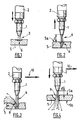
- the Figures 1 to 4 illustrate the principle of a flame cutting process of a 30 mm thick steel sheet according to the invention.
- the oxycutting process of the invention starts with a conventional and localized preheating step (in 6) of the sheet 5 to be cut, as illustrated in FIG. Figure 1 by sending to the nozzle (or nozzles) 1 of an oxygen cutting torch 2, a gas mixture formed of oxygen and a combustible gas to establish a heating flame 3 whose objective is to preheat the sheet 5 to be cut so that it reaches locally (at 6) its ignition temperature of about 1150 ° C, so as to maintain homogeneity of the oxygen jet cutting subsequently distributed.
- the heating flame must be capable of carrying, very rapidly and locally, the surface of the sheet to the ignition temperature of the material, typically of the order of about 1150 ° C for steel.
- the heating flame consists of a dart and a plume.
- the stinger is the surface on which combustion of the mixture of the oxidant gas and the combustible gas introduced into the torch occurs. This combustion makes it possible to obtain very high temperatures.
- the amount of energy that can be transmitted to the sheet is a function of the power of the sting. Also, it is necessary that this power is concentrated on a small surface in order to obtain a strong heating of the place where the cutting operation begins. This amount of energy is defined by the specific power (power per unit area given in KJ / cm 2 .s)
- Acetylene is the gas with the highest specific power: 8 KJ / cm 2 .s for a mixture having a 1/1 volume ratio. This power can reach 16 KJ / cm 2 .s with a ratio of 1m 3 of combustible gas for 2 m 3 of oxygen.
- a jet of cutting oxygen 4 is sent to the preheated zone 6, as shown in FIG. Figure 2 while proceeding preferentially to a slight rise, that is to say a distance from the cutting nozzle 1 of the upper surface 5a of the part 5 to be cut, preferably a distance of a distance "d" from the approximately 2 cm to 3 cm.
- the pressure (and / or the flow rate) of the cutting oxygen jet 4 for example limiting the pressure to a maximum value of the order of 0.2 to 1 bar, then begin to slowly move the torch 2 relatively to the part 5 to cut according to the desired cutting path, that is to say in the direction of the arrow 10 of the Figure 3 , so as to obtain an evacuation of the molten metal towards the rear portion 9 of the cutting groove being formed.
- the movement of the torch 2 begins while the sheet 5 is not yet pierced along its entire thickness.
- the pressure and / or the flow rate of the cutting oxygen jet 4 sent to the bleed 9 being formed is progressively increased, while bringing the torch 2 closer to the upper surface 5a of the sheet. 5 and continuing the movement (in the direction 10) of the torch 2 along the desired cutting path.
- the invention begins to drill and cut the sheet 5, after the localized preheating 6 of the sheet 5, using a pressure and / or an oxygen flow rate of the oxygen jet 4 which are / are lower than those used during the actual cutting.
- the oxygen cutting is done normally, that is to say according to an exothermic combustion process which consists in burning the iron of the steel constituting the sheet 5 by oxygen under pressure with a formation of oxides of iron.
- the iron oxides form a molten slag evacuated from the flame cutting groove 9 under the effect of the pressure of the cutting oxygen jet 4, that is to say expelled below the sheet 5.
- the combustion reaction is initiated with a gaseous mixture comprising oxygen as an oxidant and a combustible gas, such as acetylene, which is "ignited” so as to obtain a combustion flame serving to bring the metal to its ignition temperature and then to trigger the actual combustion of the iron ( Fig. 2 to 4 ) of the iron it contains.
- a gaseous mixture comprising oxygen as an oxidant and a combustible gas, such as acetylene, which is "ignited” so as to obtain a combustion flame serving to bring the metal to its ignition temperature and then to trigger the actual combustion of the iron ( Fig. 2 to 4 ) of the iron it contains.
- the maintenance of the combustion reaction of the metal is done by sending only oxygen under pressure, during the entire cutting of the room.
- the oxygen cutting according to the invention can be carried out manually or on a machine, in particular on a machine equipped with several torches 2 operating in parallel. to perform the cutting of identical parts (large series) within a steel sheet or the like.
- the method according to the invention is particularly suitable for cutting a sheet having a thickness of between 25 to 30 mm and 140 mm, typically of the order of about 30 to 100 mm.
- the method of the invention can be implemented with a simple flame cutting nozzle or with a nozzle with a double flow of oxygen. These two types of nozzles are perfectly common.
- a simple nozzle typically consists of an elongated body comprising an axial central passage of oxygen capable of delivering a central jet of oxygen, and one or more peripheral passages of gas capable of delivering, during the preheating phase, which is sometimes called priming phase, one or more peripheral gas streams fuel mixing with oxygen and being burned to give the combustion flame, called heating flame, used during the localized preheating of the sheet.
- a dual oxygen flow nozzle is similar to a single nozzle but further includes one or more additional internal gas passages, in fluid communication with the central oxygen passageway, which are capable of deflecting a portion of the central flow of oxygen. oxygen and distribute it around the central jet of oxygen cutting so as to create a curtain or oxygen cladding around the central jet of oxygen, during cutting.
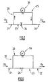
- the implementation of the invention can be done by means of a gas circuit 20, such as that illustrated on the Figures 5 and 6 which is connected to each of the torches 2 provided with a nozzle 1.
- the Figure 5 represents the circuit 20 in the 'closed' position, that is to say in the configuration which must be adopted during the preheating and the start of cutting until the actual piercing of the part 5, as illustrated in FIGS. Figures 1 to 3
- Figure 6 represents the circuit 20 in the 'open' position, that is to say in the configuration that must be adopted after drilling and when cutting, as illustrated in FIG. Figure 4 .
- the gas circuit 20 comprises a main pipe 23 of gas with an inlet 21 for oxygen (O 2 ) under pressure, for example at 10 bar, and an oxygen outlet 22 fluidly connected to the (x ) torch (x).
- the main pipe 23 further comprises a valve, for example 1 ⁇ 4 turn, to control the passage of gas in the main pipe 23, especially during cutting (cf. Fig. 4 ).
- the circuit 20 comprises a bypass line 25 or bypass for passing the valve 24, on which is arranged a gas expander 26 for controlling the pressure (or flow) of the gas flowing in this branch line 25, for example a pressure reducer 26 having a working range from 0 to 2 bar.
- valve 24 moves to the "open" position and the circuit 20 is found in the configuration of the Figure 6 to make the actual cutting, as illustrated on the Figure 4 .
- the gas then passes essentially through the main line 23 through the valve 24 without undergoing expansion. It is therefore send under high pressure (10 bar) to the torch.
- the valve 24 may be a solenoid valve controlled automatically, or remotely, by a digital CNC type console or any control cabinet or computer adapted.
- the pressure level of the expander 26 can also be controlled automatically by a CNC or the like.
- valve 24 it is essentially the control of the valve 24 that will vary the oxygen pressure and thus move from one stage to another of the method of the invention.
- control of the valve 24 is synchronized or coordinated with the control of movements away or closer to the nozzle carried by the torch of the upper surface of the plate to be cut, and with that relative movement of the torch relative to said plate to be cut, as explained above.
- the circuit 20 and its various components can be fixed by means of a support and fixing plate or any other similar system on the flame cutting machine.
- each torch can be fed by a circuit 20 of gas supply ducts dedicated to it and dedicated to this torch, or the same circuit 20 can supply gas to several torches.
Landscapes
- Engineering & Computer Science (AREA)
- Mechanical Engineering (AREA)
- Gas Burners (AREA)
- Laser Beam Processing (AREA)
- Arc Welding In General (AREA)
Description
- La présente invention concerne un procédé d'oxycoupage d'une pièce conformément au préambule de la revendication 1 (voir, par example,
JP 59/070464 - L'oxycoupage est un procédé de découpe largement utilisé pour la découpe des aciers ou plus généralement des matériaux ferreux, c'est-à-dire renfermant du fer.
- Au plan industriel, ce procédé est mis en oeuvre sur des installations ou des machines comprenant 1 ou 2 chalumeaux sur les installations les plus simples, et jusqu'à 6 à 12 chalumeaux fonctionnant en parallèle, pour les plus complexes, typiquement une machine d'oxycoupage comprend de 1 à 8 chalumeaux.
- En fait, l'oxycoupage est un procédé de découpe par combustion localisée et continue du métal par un jet d'oxygène pur. Ce procédé est bien connu dans l'industrie. Le procédé est d'abord initié avec une flamme oxycombustible à haute température, pendant la phase dite d'amorçage ou de préchauffage, permettant de porter localement la pièce à couper à sa température d'inflammation, c'est-à-dire typiquement de l'ordre de 1150°C, puis la réaction de combustion est débutée puis entretenue par envoi d'un jet d'oxygène, durant la phase de perçage puis de coupe proprement dite et ce, tout au long de la trajectoire de coupe désirée.
- Les matériaux pouvant être oxycoupés sont principalement ceux contenant du fer, en particulier les aciers faiblement alliés ou non alliés, notamment les aciers au carbone.
- Les principaux paramètres influençant les performances de coupes sont le matériel de coupe, en particulier le choix de la buse de coupage, la qualité des gaz (combustible et oxygène), le matériau à découper et le savoir-faire de l'opérateur.
- L'oxycoupage est principalement utilisé pour la découpe de pièces d'acier d'épaisseur supérieure à 10 mm car sur des épaisseurs inférieures, les limites du procédé sont atteintes, à savoir une qualité et des performances de coupe non acceptables au plan industriel.
- Pour les épaisseurs supérieures à 30 mm, lors du perçage en pleine tôle de la pièce à couper, juste après le préchauffage de celle-ci, on a remarqué qu'il existait également certains problèmes récurrents, tels que des remontées de métal en fusion sur la buse, des retours de flammes intempestifs provoquant des dégradations du matériel de coupe, des défauts de coupes dues à des buses encrassées, des défauts de perpendicularité des faces de coupe et des difficultés à démarrer la coupe.
- En fait, la plupart de ces problèmes sont engendrés ou résultent des projections adhérentes de métal en fusion qui se produisent juste après le préchauffage de la tôle, c'est-à-dire pendant le perçage de la tôle.
- Ce phénomène s'accentue lorsqu'on utilise une buse à haute pression, typiquement plus de 8 bar, et ayant un débit d'oxygène élevé, c'est-à-dire d'au moins 3900 1/h, du fait de la réaction immédiate qui se produit avec l'oxygène amené en grande quantité.
- Ce phénomène est par ailleurs encore amplifié lorsque plusieurs chalumeaux d'oxycoupage fonctionnent en parallèle, ainsi que lors de l'utilisation de buses dite à Haute Pression qui ont des débits instantanés d'oxygène de coupe de 7 à 12 bar.
- Le but de l'invention est dès lors de proposer un procédé d'oxycoupage amélioré permettant d'éviter ou de minimiser tout ou partie des problèmes susmentionnés de manière à minimiser ou à éviter les projections de métal en fusion, lors du perçage de la tôle, en début de coupage.
- La solution de l'invention est un procédé d'oxycoupage d'une pièce en un métal contenant du fer conformément à la revendication 1.
- Selon le cas, le procédé de l'invention peut comprendre l'une ou plusieurs des caractéristiques suivantes :
- le gaz combustible de l'étape a) et l'oxygène des étapes a), b) et c) sont distribués par la buse qui est située en regard de la surface supérieure de la pièce.
- à l'étape a), le préchauffage est effectué jusqu'à atteindre au moins la température d'inflammation du métal de la pièce, au niveau de ladite zone localisé de la pièce, de préférence une température supérieure ou égale à 1150°C.
- à l'étape b), on opère en outre un éloignement de la buse de la surface supérieure de la pièce de manière à positionner ladite buse à une distance de perçage (d) comprise entre 1 et 5 cm, typiquement de l'ordre de 2 cm à 3 cm, de la surface supérieure de la pièce.
- après éloignement de la buse de la surface supérieure de la pièce mais préalablement à l'obtention du perçage selon toute l'épaisseur de la pièce, on opère un déplacement relatif de la buse par rapport à la pièce de manière au moins initier une saignée de coupe.
- la première pression d'oxygène est inférieure à 2 bar environ et la deuxième pression d'oxygène est supérieure à 2 bar, de préférence supérieure à 5 bar.
- l'épaisseur de la pièce est supérieure à 25 mm, de préférence comprise entre 30 et 100 mm.
- la pièce est en acier.
- le gaz combustible utilisé à l'étape a) contient de l'acétylène, de l'éthylène, du gaz naturel ou du GPL (gaz de pétrole liquéfié).
- il met en oeuvre plusieurs buses de coupe agencées sur plusieurs chalumeaux fonctionnant simultanément pour réaliser concomitamment plusieurs découpages au sein de ladite pièce.
- L'invention va maintenant être mieux comprise grâce à la description détaillée suivante du principe de perçage et du mode opératoire, faite en références aux Figures annexées.
- Les
figures 1 à 4 illustrent le principe d'un procédé d'oxycoupage d'une tôle en acier de 30 mm d'épaisseur selon l'invention. - Le procédé d'oxycoupage de l'invention débute avec une étape de préchauffage classique et localisé (en 6) de la tôle 5 à couper, comme illustré en
Figure 1 , par envoi vers la (ou les) buse 1 d'un chalumeau d'oxycoupage 2, d'un mélange gazeux formé d'oxygène et d'un gaz combustible pour établir une flamme 3 de chauffe dont l'objectif est de préchauffer la tôle 5 à couper pour qu'elle atteigne localement (en 6) sa température d'inflammation d'environ 1150°C, de manière à maintenir une homogénéité du jet d'oxygène de coupe distribué subséquemment. - En effet, pour réaliser une opération d'oxycoupage, il est nécessaire de mettre en oeuvre successivement au moins une flamme dite « de chauffe » et un jet d'oxygène central dit « oxygène de coupe ».
- La flamme de chauffe doit être capable de porter, très rapidement et localement, la surface de la tôle à la température d'inflammation du matériau, à savoir classiquement de l'ordre d'environ 1150° C pour de l'acier.
- Lorsque celle-ci est atteinte, l'oxygène de coupe est libéré et la réaction de combustion du fer contenu dans l'acier débute. Il est donc primordial de bien définir le gaz combustible le plus adapté pour atteindre rapidement la température d'inflammation.
- En fait, plusieurs mélanges de gaz combustibles et d'oxygène permettent d'obtenir une température supérieure à 1500° C. Ceux-ci sont donnés dans le Tableau suivant.
Tableau Mélange gazeux Température atteinte (en °C) O2 + acétylène 3150 O2 + éthylène 2924 O2 + hydrogène 2856 O2 + propane 2830 - La flamme de chauffe se compose d'un dard et d'un panache. En oxycoupage, seules les propriétés du dard de la flamme sont intéressantes. Le dard est la surface sur laquelle se produit la combustion du mélange du gaz comburant et du gaz combustible introduit dans le chalumeau. Cette combustion permet d'obtenir des températures très élevées. La quantité d'énergie qu'il est possible de transmettre à la tôle est fonction de la puissance de ce dard. Aussi, il faut que cette puissance soit concentrée sur une petite surface afin d'obtenir un fort échauffement de l'endroit ou débute l'opération de découpe. Cette quantité d'énergie est définie par la puissance spécifique (puissance par unité de surface donnée en KJ/cm2.s)
- L'acétylène est le gaz ayant la plus forte puissance spécifique : 8 KJ/cm2.s pour un mélange ayant un rapport de volume 1/1. Cette puissance peut atteindre 16 KJ/cm2.s avec un rapport de 1m3 de gaz combustible pour 2 m3 d'oxygène.
- C'est également l'acétylène qui détient la plus grande vitesse de déflagration dans l'oxygène. Cette notion est importante car elle informe de la sensibilité aux retours de flamme et reste un des facteurs bloquant à l'utilisation en oxycoupage sur machine.
- Une fois la température d'inflammation atteinte, par exemple après un temps de chauffage donné préfixé, on opère un envoi d'un jet 4 d'oxygène de coupe vers la zone préchauffée 6, comme montré en
Figure 2 , tout en procédant préférentiellement à une légère remontée, c'est-à-dire un éloignement de la buse 1 de coupe de la surface supérieure 5a de la pièce 5 à couper, de préférence un éloignement d'une distance « d » de l'ordre de 2 cm à 3 cm environ. - Afin d'éviter les projections de métal en fusion, il conviendra de contrôler la pression (et/ou le débit) du jet d'oxygène 4 de coupe, par exemple limiter la pression à une valeur maximale de l'ordre de 0,2 à 1 bar, puis de commencer à déplacer lentement le chalumeau 2 relativement par rapport à la pièce 5 à couper selon la trajectoire de coupe désirée, c'est-à-dire dans le sens de la flèche 10 de la
Figure 3 , de manière à obtenir une évacuation du métal fondu vers la partie arrière 9 de la saignée de coupe en cours de formation. - Selon l'invention, le déplacement du chalumeau 2 commence alors que la tôle 5 n'est pas encore percée selon la totalité de son épaisseur.
- Après avoir décalé le chalumeau, on augmente progressivement la pression et/ou le débit du jet 4 d'oxygène de coupe envoyé vers la saignée 9 en cours de formation, tout en rapprochant à nouveau le chalumeau 2 de la surface supérieure 5a de la tôle 5 et en continuant le déplacement (selon la direction 10) du chalumeau 2 le long de la trajectoire de coupe souhaitée.
- En d'autres termes, selon l'invention, on commence à percer et à couper la tôle 5, postérieurement au préchauffage localisé 6 de la tôle 5, en utilisant une pression et/ou un débit d'oxygène du jet d'oxygène 4 qui est/sont inférieurs à ceux mis en oeuvre pendant le coupage proprement dit.
- Ensuite, l'oxycoupage se fait normalement, c'est-à-dire selon un processus de combustion exothermique qui consiste à brûler le fer de l'acier constituant la tôle 5 par de l'oxygène sous pression avec une formation d'oxydes de fer. Les oxydes de fer forment un laitier en fusion évacué de la saignée 9 d'oxycoupage sous l'effet de la pression du jet d'oxygène 4 de coupe, c'est-à-dire expulsé en dessous de la tôle 5.
- Pendant la phase de préchauffage (
Fig. 1 ), l'initiation de la réaction de combustion se fait avec un mélange gazeux comprenant de l'oxygène en tant que comburant et un gaz combustible, tel que l'acétylène, qui est « allumé » de manière à obtenir une flamme de combustion servant à porter le métal à sa température d'inflammation et à déclencher ensuite la combustion proprement dite du fer (Fig. 2 à 4 ) du fer qu'il contient. L'entretien de la réaction de combustion du métal se fait par envoi uniquement de l'oxygène sous pression, durant toute la coupe de la pièce. - L'oxycoupage selon l'invention peut être réalisé manuellement ou sur une machine, en particulier sur une machine équipée de plusieurs chalumeaux 2 fonctionnant en parallèle pour réaliser la découpe de pièces identiques (grandes séries) au sein d'une tôle d'acier ou analogue.
- Le procédé selon l'invention particulièrement adapté au coupage d'une tôle ayant une épaisseur comprise entre 25 à 30 mm et 140 mm, typiquement de l'ordre de 30 à 100 mm environ.
- Le procédé de l'invention peut être mis en oeuvre avec une buse d'oxycoupage simple ou alors avec une buse à double flux d'oxygène. Ces deux types de buses sont parfaitement usuels.
- Ainsi, une buse simple se compose typiquement d'un corps allongé comprenant un passage central axial d'oxygène apte à délivrer un jet central d'oxygène, et un ou plusieurs passages périphériques de gaz apte à délivrer, pendant la phase de préchauffage, qui est parfois appelée phase d'amorçage, un ou plusieurs jets périphériques de gaz combustible venant se mélanger avec l'oxygène et étant brûler en donnant la flamme de combustion, dite flamme de chauffe, servant durant le préchauffage localisé de la tôle.
- Un buse à double flux d'oxygène est similaire à une buse simple mais comprend en outre un ou plusieurs passages internes supplémentaires de gaz, en communication fluidique avec le passage central d'oxygène, qui sont aptes à dévier une partie du flux central d'oxygène et de le distribuer autour du jet central d'oxygène de coupe de manière à créer un rideau ou gainage d'oxygène autour du jet central d'oxygène, pendant la coupe.
- La mise en oeuvre de l'invention peut se faire au moyen d'un circuit de gaz 20, tel celui illustré sur les
Figures 5 et 6 , qui est relié à chacun des chalumeaux 2 munis d'une buse 1. - La
Figure 5 représente le circuit 20 en position 'fermée', c'est-à-dire dans la configuration qui doit être adoptée lors du préchauffage et du début de coupe jusqu'au perçage proprement dit de la pièce 5, comme illustré sur lesFigures 1 à 3 , alors que laFigure 6 représente le circuit 20 en position 'ouverte', c'est-à-dire dans la configuration qui doit être adoptée après perçage et lors du coupage, comme illustré sur laFigure 4 . - Comme on le voit, le circuit 20 de gaz comprend une canalisation principale 23 de gaz avec une entrée 21 pour l'oxygène (O2) sous pression, par exemple à 10 bar, et une sortie d'oxygène 22 reliée fluidiquement au(x) chalumeau(x).
- La canalisation principale 23 comprend en outre une vanne, par exemple de type ¼ de tour, permettant de contrôler le passage de gaz dans la canalisation 23 principale, en particulier durant la coupe (cf.
Fig. 4 ). - Par ailleurs, le circuit 20 comporte une ligne de dérivation 25 ou bipasse permettant de bipasser la vanne 24, sur laquelle est agencé un détendeur 26 de gaz permettant de contrôler la pression (ou le débit) du gaz circulant dans cette ligne de dérivation 25, par exemple un détendeur 26 ayant une plage de travail allant de 0 à 2 bar.
- Lorsque le circuit 20 est en position « fermée », comme illustré en
Figure 5 , alors l'oxygène sous haute pression (10 bar) arrivant par l'entrée 21, transite par la ligne de dérivation 25 mais pas par la ligne principale 23 puisque que la vanne 24 est fermée. Le gaz subit alors une détente dans le détendeur 26 jusqu'à la pression basse souhaitée, par exemple 0,5 bar, mise en oeuvre durant les étapes illustrées sur lesfigures 1 à 3 , puis est convoyé vers la sortie 22, en direction du chalumeau. - Lorsque le perçage est obtenu, la vanne 24 passe en position « ouverte » et le circuit 20 se retrouve dans la configuration de la
Figure 6 pour opérer le coupage proprement dit, tel qu'illustré sur laFigure 4 . Le gaz transite alors essentiellement par la ligne principale 23 au travers de la vanne 24 sans y subir de détente. Il est donc envoyer sous haute pression (10 bar) vers le chalumeau. - La vanne 24 peut être une électrovanne commandée automatiquement, voire à distance, par une console numérique de type CNC ou toute armoire de commande ou ordinateur adapté.
- De même, le niveau de pression du détendeur 26 peut également être piloté automatiquement par une CNC ou analogue.
- En fait, c'est essentiellement le pilotage de la vanne 24 qui permettra de varier la pression d'oxygène donc de passer d'une étape à l'autre du procédé de l'invention.
- Il va de soi que le pilotage de la vanne 24 se fait de manière synchronisée ou coordonnée avec le pilotage des mouvements en éloignement ou en rapprochement de la buse portée par le chalumeau de la surface supérieure de la plaque à couper, ainsi qu'avec celui du mouvement de déplacement relatif du chalumeau par rapport à ladite plaque à couper, comme expliqué ci-avant.
- Le circuit 20 et ses différents composants peuvent être fixés au moyen d'une plaque de support et de fixation ou tout autre système analogue sur la machine d'oxycoupage.
- Lorsque plusieurs chalumeaux sont utilisés en parallèle, chaque chalumeau peut être alimenté par un circuit 20 de conduits d'amenée gaz qui lui est propre et dédié à ce chalumeau, ou alors un même circuit 20 peut alimenter en gaz plusieurs chalumeaux.
Claims (7)
- Procédé d'oxycoupage d'une pièce (5, 5a, 5b) en un métal contenant du fer, mettant en oeuvre au moins un chalumeau (2) muni d'une buse de coupe (1), dans lequel on opère selon les étapes de :a) préchauffage d'une zone localisé (6) de la pièce (5, 5a, 5b) au moyen d'une flamme (3) obtenue par combustion d'un gaz combustible et d'oxygène, etb) envoi en direction de la zone localisé (6) préchauffée à l'étape a), d'oxygène gazeux à une première pression et/ou à un premier débit pour initier une amorce de perçage tout en décalant le chalumeau (2) dans le sens (10) de la coupe,
caractérisé en ce qu'il comporte en outre l'étape c) suivante :c) après l'amorce de perçage de la pièce à l'étape b), augmenter la pression et/ou le débit de l'oxygène gazeux envoyé en direction de la zone de début de perçage jusqu'à une deuxième pression supérieure à la première pression et/ou à un deuxième débit supérieur au premier débit pour obtenir le perçage total de la pièce (5, 5a, 5b), et on opère un rapprochement de la buse (1) de la surface supérieure (5a) de la pièce (5) jusqu'à une distance de coupe (d') comprise entre 0,5 et 1,5 cm, avec d' < d, concomitamment à l'augmentation de la pression et/ou du débit d'oxygène gazeux envoyé en direction de la zoné percée. - Procédé selon la revendication 1, caractérisé en ce que le gaz combustible de l'étape a) et l'oxygène des étapes a), b) et c) sont distribués par la buse (1) qui est située en regard de la surface supérieure (5a) de la pièce (5).
- Procédé selon l'une des revendications précédentes, caractérisé en ce qu'à l'étape a), le préchauffage est effectué jusqu'à atteindre au moins la température d'inflammation du métal de la pièce, au niveau de ladite zone localisé (6) de la pièce (5, 5a, 5b), de préférence une température supérieure ou égale à 1150°C.
- Procédé selon l'une des revendications précédentes, caractérisé en ce qu'à l'étape b), on opère en outre un éloignement de la buse (1) de la surface supérieure (5a) de la pièce de manière à positionner ladite buse à une distance de perçage (d) comprise entre 1 et 5 cm, typiquement de l'ordre de 2 cm à 3 cm, de 1a surface supérieure (5a) de la pièce (5).
- procédé selon l'une des revendications précédentes, caractérisé en ce qu'après éloignement de la buse (1) de la surface supérieure (5a) de la pièce mais préalablement à l'obtention du perçage selon toute l'épaisseur de la pièce (5), on opère un déplacement relatif de la buse (1) par rapport à la pièce (5) de manière au moins initier une saignée de coupe (9).
- Procédé selon l'une des revendications précédentes, caractérisé que la première pression d'oxygène est inférieure à 2 bar environ et la deuxième pression d'oxygène est supérieure à 2 bar, de préférence supérieure à 5 bar.
- Procédé selon l'une des revendications précédentes, caractérisé en ce qu'il met en oeuvre plusieurs buses (1) de coupe agencées sur plusieurs chalumeaux (2) fonctionnant simultanément pour réaliser concomitamment plusieurs découpages au sein de ladite pièce (5, 5a, 5b).
Priority Applications (1)
| Application Number | Priority Date | Filing Date | Title |
|---|---|---|---|
| PL09745949T PL2282866T3 (pl) | 2008-04-24 | 2009-04-16 | Sposób cięcia gazowego części ze stali ze zwiększaniem ciśnienia i/lub natężenia przepływu gazowego tlenu po zapoczątkowaniu przebijania |
Applications Claiming Priority (2)
| Application Number | Priority Date | Filing Date | Title |
|---|---|---|---|
| FR0852747A FR2930468B1 (fr) | 2008-04-24 | 2008-04-24 | Procede et installation d'oxycoupage d'une piece en acier |
| PCT/FR2009/050706 WO2009138630A2 (fr) | 2008-04-24 | 2009-04-16 | Procede et installation d'oxycoupage d'une piece en acier |
Publications (2)
| Publication Number | Publication Date |
|---|---|
| EP2282866A2 EP2282866A2 (fr) | 2011-02-16 |
| EP2282866B1 true EP2282866B1 (fr) | 2012-01-18 |
Family
ID=40040032
Family Applications (1)
| Application Number | Title | Priority Date | Filing Date |
|---|---|---|---|
| EP09745949A Not-in-force EP2282866B1 (fr) | 2008-04-24 | 2009-04-16 | Procede d'oxycoupage d'une piece en acier avec augmentation de la pression et/ou du debit de l'oxygene gazeux apres amorcage du percage |
Country Status (8)
| Country | Link |
|---|---|
| US (1) | US20110036461A1 (fr) |
| EP (1) | EP2282866B1 (fr) |
| CN (1) | CN102015185B (fr) |
| AT (1) | ATE541665T1 (fr) |
| CA (1) | CA2717194A1 (fr) |
| FR (1) | FR2930468B1 (fr) |
| PL (1) | PL2282866T3 (fr) |
| WO (1) | WO2009138630A2 (fr) |
Families Citing this family (7)
| Publication number | Priority date | Publication date | Assignee | Title |
|---|---|---|---|---|
| CN102784996B (zh) * | 2012-08-28 | 2014-10-15 | 北京中气华辰新能源技术开发有限公司 | 氢氧燃气切割枪及其枪体 |
| DE102013210844B3 (de) * | 2013-06-11 | 2014-09-25 | Trumpf Werkzeugmaschinen Gmbh + Co. Kg | Verfahren zum Bilden eines Durchgangslochs in einem metallischen Werkstück, Laserbearbeitungsmaschine und Computerprogrammprodukt |
| CN106312238B (zh) * | 2016-08-31 | 2018-10-02 | 安徽景隆金属材料有限公司 | 一种厚钢板火焰切割方法 |
| CN116171204A (zh) * | 2020-09-07 | 2023-05-26 | Emc概念 | 用于火焰切割含铁金属工件的方法及其实施设备 |
| JP7557782B2 (ja) | 2021-02-26 | 2024-09-30 | 株式会社群馬コイケ | ピアシング方法 |
| CN116000407B (zh) * | 2023-03-22 | 2023-06-27 | 哈尔滨电机厂有限责任公司 | 一种特厚钢板起弧孔穿孔装置及穿孔方法 |
| CN119140942B (zh) * | 2024-11-15 | 2025-01-07 | 深圳市蓝海永兴实业有限公司 | 一种定位式切割设备 |
Family Cites Families (7)
| Publication number | Priority date | Publication date | Assignee | Title |
|---|---|---|---|---|
| GB853088A (en) * | 1959-01-09 | 1960-11-02 | Union Carbide Corp | Improvements in and relating to the selective removal of surface defects from metal bodies by thermochemical descarfing |
| DE2247012C2 (de) * | 1972-09-25 | 1974-06-27 | Messer Griesheim Gmbh, 6000 Frankfurt | Einrichtung an einer Brennschneidmaschine zur Zuführung von Gasen |
| JPS5633169A (en) * | 1979-08-23 | 1981-04-03 | Hitachi Constr Mach Co Ltd | Boring in gas cutting and its apparatus |
| JPS5970464A (ja) * | 1982-10-14 | 1984-04-20 | Nippon Steel Corp | ガス溶削穿孔方法 |
| JPS60145273A (ja) * | 1984-01-09 | 1985-07-31 | Mitsubishi Electric Corp | ガス切断方法 |
| JPH0635068B2 (ja) * | 1986-06-20 | 1994-05-11 | 株式会社田中製作所 | プラズマ切断法 |
| JPH1080764A (ja) * | 1996-09-09 | 1998-03-31 | Tanaka Seisakusho Kk | 切断機 |
-
2008
- 2008-04-24 FR FR0852747A patent/FR2930468B1/fr not_active Expired - Fee Related
-
2009
- 2009-04-16 AT AT09745949T patent/ATE541665T1/de active
- 2009-04-16 CA CA2717194A patent/CA2717194A1/fr not_active Abandoned
- 2009-04-16 US US12/989,153 patent/US20110036461A1/en not_active Abandoned
- 2009-04-16 EP EP09745949A patent/EP2282866B1/fr not_active Not-in-force
- 2009-04-16 WO PCT/FR2009/050706 patent/WO2009138630A2/fr not_active Ceased
- 2009-04-16 PL PL09745949T patent/PL2282866T3/pl unknown
- 2009-04-16 CN CN2009801143423A patent/CN102015185B/zh not_active Expired - Fee Related
Also Published As
| Publication number | Publication date |
|---|---|
| EP2282866A2 (fr) | 2011-02-16 |
| CN102015185A (zh) | 2011-04-13 |
| CA2717194A1 (fr) | 2009-11-19 |
| FR2930468A1 (fr) | 2009-10-30 |
| US20110036461A1 (en) | 2011-02-17 |
| CN102015185B (zh) | 2013-08-21 |
| FR2930468B1 (fr) | 2010-08-27 |
| ATE541665T1 (de) | 2012-02-15 |
| PL2282866T3 (pl) | 2012-07-31 |
| WO2009138630A3 (fr) | 2010-01-07 |
| WO2009138630A2 (fr) | 2009-11-19 |
Similar Documents
| Publication | Publication Date | Title |
|---|---|---|
| EP2282866B1 (fr) | Procede d'oxycoupage d'une piece en acier avec augmentation de la pression et/ou du debit de l'oxygene gazeux apres amorcage du percage | |
| FR2852541A1 (fr) | Procede de coupage plasma avec double flux de gaz | |
| US2470999A (en) | Thermochemical metal removal | |
| US20080302767A1 (en) | Plasma Cutting Machine | |
| US11920097B2 (en) | Oxy fuel gas mixtures and methods for use | |
| EP1140412B1 (fr) | Procede d'oxycoupage avec prechauffage par plasma de materiaux ferreux, tels les aciers de construction | |
| JP2010000511A (ja) | 鋼板のガス切断方法及び装置 | |
| CN105252104B (zh) | 一种钢板的火焰切割方法 | |
| KR100960845B1 (ko) | 플라즈마 절단 장치 및 방법 | |
| EP0952205A1 (fr) | Mélange gazeux contenant de l'acétylène et de l'hydrogène et/ou du gaz naturel | |
| US2510210A (en) | Method of thermochemically cutting metal bodies | |
| US20080115862A1 (en) | Method for thermal cutting | |
| JP4875949B2 (ja) | ガス切断方法 | |
| US934235A (en) | Process for cutting metal objects. | |
| EP1578177A1 (fr) | Procédé de coupage plasma avec double flux de gaz | |
| FR2745064A1 (fr) | Installation et procede de mise en oeuvre d'une flamme | |
| JP5738254B2 (ja) | 可燃性ガスおよび鋼材の溶断方法 | |
| FR2943568A1 (fr) | Procede de coupage plasma avec controle de l'extinction de l'arc en fin de coupe | |
| FR2958371A1 (fr) | Adaptateur pour chalumeau d'oxycoupage sans premelange interne de gaz | |
| JP2000280079A (ja) | ガス圧接方法 | |
| FR2928286A1 (fr) | Procede d'oxycoupage de paquets de toles empilees | |
| CA2460635A1 (fr) | Procede de coupage plasma avec double flux de gaz | |
| FR2774693A1 (fr) | Melange gazeux combustible, notamment pour chalumeau d'oxycoupage | |
| JPS58199683A (ja) | ガス加圧溶接方法 | |
| FR2864953A1 (fr) | Procede de production de noir de carbone par craquage d'un hydrocarbure allume par un gaz chaud |
Legal Events
| Date | Code | Title | Description |
|---|---|---|---|
| PUAI | Public reference made under article 153(3) epc to a published international application that has entered the european phase |
Free format text: ORIGINAL CODE: 0009012 |
|
| 17P | Request for examination filed |
Effective date: 20101124 |
|
| AK | Designated contracting states |
Kind code of ref document: A2 Designated state(s): AT BE BG CH CY CZ DE DK EE ES FI FR GB GR HR HU IE IS IT LI LT LU LV MC MK MT NL NO PL PT RO SE SI SK TR |
|
| AX | Request for extension of the european patent |
Extension state: AL BA RS |
|
| GRAP | Despatch of communication of intention to grant a patent |
Free format text: ORIGINAL CODE: EPIDOSNIGR1 |
|
| DAX | Request for extension of the european patent (deleted) | ||
| RTI1 | Title (correction) |
Free format text: METHOD OF FLAME CUTTING A STEEL PART, WITH AN INCREASE IN THE PRESSURE AND/OR FLOW RATE OF THE GASEOUS OXYGEN AFTER INITIATION OF PIERCING |
|
| GRAS | Grant fee paid |
Free format text: ORIGINAL CODE: EPIDOSNIGR3 |
|
| GRAA | (expected) grant |
Free format text: ORIGINAL CODE: 0009210 |
|
| AK | Designated contracting states |
Kind code of ref document: B1 Designated state(s): AT BE BG CH CY CZ DE DK EE ES FI FR GB GR HR HU IE IS IT LI LT LU LV MC MK MT NL NO PL PT RO SE SI SK TR |
|
| REG | Reference to a national code |
Ref country code: GB Ref legal event code: FG4D Free format text: NOT ENGLISH |
|
| REG | Reference to a national code |
Ref country code: CH Ref legal event code: EP |
|
| REG | Reference to a national code |
Ref country code: AT Ref legal event code: REF Ref document number: 541665 Country of ref document: AT Kind code of ref document: T Effective date: 20120215 Ref country code: IE Ref legal event code: FG4D Free format text: LANGUAGE OF EP DOCUMENT: FRENCH |
|
| REG | Reference to a national code |
Ref country code: DE Ref legal event code: R096 Ref document number: 602009004782 Country of ref document: DE Effective date: 20120322 |
|
| REG | Reference to a national code |
Ref country code: NL Ref legal event code: VDEP Effective date: 20120118 |
|
| LTIE | Lt: invalidation of european patent or patent extension |
Effective date: 20120118 |
|
| PG25 | Lapsed in a contracting state [announced via postgrant information from national office to epo] |
Ref country code: HR Free format text: LAPSE BECAUSE OF FAILURE TO SUBMIT A TRANSLATION OF THE DESCRIPTION OR TO PAY THE FEE WITHIN THE PRESCRIBED TIME-LIMIT Effective date: 20120118 Ref country code: NO Free format text: LAPSE BECAUSE OF FAILURE TO SUBMIT A TRANSLATION OF THE DESCRIPTION OR TO PAY THE FEE WITHIN THE PRESCRIBED TIME-LIMIT Effective date: 20120418 Ref country code: BG Free format text: LAPSE BECAUSE OF FAILURE TO SUBMIT A TRANSLATION OF THE DESCRIPTION OR TO PAY THE FEE WITHIN THE PRESCRIBED TIME-LIMIT Effective date: 20120418 Ref country code: NL Free format text: LAPSE BECAUSE OF FAILURE TO SUBMIT A TRANSLATION OF THE DESCRIPTION OR TO PAY THE FEE WITHIN THE PRESCRIBED TIME-LIMIT Effective date: 20120118 Ref country code: IS Free format text: LAPSE BECAUSE OF FAILURE TO SUBMIT A TRANSLATION OF THE DESCRIPTION OR TO PAY THE FEE WITHIN THE PRESCRIBED TIME-LIMIT Effective date: 20120518 Ref country code: LT Free format text: LAPSE BECAUSE OF FAILURE TO SUBMIT A TRANSLATION OF THE DESCRIPTION OR TO PAY THE FEE WITHIN THE PRESCRIBED TIME-LIMIT Effective date: 20120118 |
|
| REG | Reference to a national code |
Ref country code: PL Ref legal event code: T3 |
|
| REG | Reference to a national code |
Ref country code: IE Ref legal event code: FD4D |
|
| PG25 | Lapsed in a contracting state [announced via postgrant information from national office to epo] |
Ref country code: GR Free format text: LAPSE BECAUSE OF FAILURE TO SUBMIT A TRANSLATION OF THE DESCRIPTION OR TO PAY THE FEE WITHIN THE PRESCRIBED TIME-LIMIT Effective date: 20120419 Ref country code: PT Free format text: LAPSE BECAUSE OF FAILURE TO SUBMIT A TRANSLATION OF THE DESCRIPTION OR TO PAY THE FEE WITHIN THE PRESCRIBED TIME-LIMIT Effective date: 20120518 Ref country code: LV Free format text: LAPSE BECAUSE OF FAILURE TO SUBMIT A TRANSLATION OF THE DESCRIPTION OR TO PAY THE FEE WITHIN THE PRESCRIBED TIME-LIMIT Effective date: 20120118 Ref country code: FI Free format text: LAPSE BECAUSE OF FAILURE TO SUBMIT A TRANSLATION OF THE DESCRIPTION OR TO PAY THE FEE WITHIN THE PRESCRIBED TIME-LIMIT Effective date: 20120118 |
|
| REG | Reference to a national code |
Ref country code: AT Ref legal event code: MK05 Ref document number: 541665 Country of ref document: AT Kind code of ref document: T Effective date: 20120118 |
|
| PG25 | Lapsed in a contracting state [announced via postgrant information from national office to epo] |
Ref country code: CY Free format text: LAPSE BECAUSE OF FAILURE TO SUBMIT A TRANSLATION OF THE DESCRIPTION OR TO PAY THE FEE WITHIN THE PRESCRIBED TIME-LIMIT Effective date: 20120118 |
|
| BERE | Be: lapsed |
Owner name: L'AIR LIQUIDE S.A. POUR L'ETUDE ET L'EXPLOITATION Effective date: 20120430 |
|
| PG25 | Lapsed in a contracting state [announced via postgrant information from national office to epo] |
Ref country code: DK Free format text: LAPSE BECAUSE OF FAILURE TO SUBMIT A TRANSLATION OF THE DESCRIPTION OR TO PAY THE FEE WITHIN THE PRESCRIBED TIME-LIMIT Effective date: 20120118 Ref country code: IE Free format text: LAPSE BECAUSE OF FAILURE TO SUBMIT A TRANSLATION OF THE DESCRIPTION OR TO PAY THE FEE WITHIN THE PRESCRIBED TIME-LIMIT Effective date: 20120118 Ref country code: RO Free format text: LAPSE BECAUSE OF FAILURE TO SUBMIT A TRANSLATION OF THE DESCRIPTION OR TO PAY THE FEE WITHIN THE PRESCRIBED TIME-LIMIT Effective date: 20120118 Ref country code: SE Free format text: LAPSE BECAUSE OF FAILURE TO SUBMIT A TRANSLATION OF THE DESCRIPTION OR TO PAY THE FEE WITHIN THE PRESCRIBED TIME-LIMIT Effective date: 20120118 Ref country code: SI Free format text: LAPSE BECAUSE OF FAILURE TO SUBMIT A TRANSLATION OF THE DESCRIPTION OR TO PAY THE FEE WITHIN THE PRESCRIBED TIME-LIMIT Effective date: 20120118 Ref country code: EE Free format text: LAPSE BECAUSE OF FAILURE TO SUBMIT A TRANSLATION OF THE DESCRIPTION OR TO PAY THE FEE WITHIN THE PRESCRIBED TIME-LIMIT Effective date: 20120118 |
|
| PLBE | No opposition filed within time limit |
Free format text: ORIGINAL CODE: 0009261 |
|
| STAA | Information on the status of an ep patent application or granted ep patent |
Free format text: STATUS: NO OPPOSITION FILED WITHIN TIME LIMIT |
|
| PG25 | Lapsed in a contracting state [announced via postgrant information from national office to epo] |
Ref country code: MC Free format text: LAPSE BECAUSE OF NON-PAYMENT OF DUE FEES Effective date: 20120430 Ref country code: SK Free format text: LAPSE BECAUSE OF FAILURE TO SUBMIT A TRANSLATION OF THE DESCRIPTION OR TO PAY THE FEE WITHIN THE PRESCRIBED TIME-LIMIT Effective date: 20120118 |
|
| 26N | No opposition filed |
Effective date: 20121019 |
|
| PG25 | Lapsed in a contracting state [announced via postgrant information from national office to epo] |
Ref country code: AT Free format text: LAPSE BECAUSE OF FAILURE TO SUBMIT A TRANSLATION OF THE DESCRIPTION OR TO PAY THE FEE WITHIN THE PRESCRIBED TIME-LIMIT Effective date: 20120118 Ref country code: BE Free format text: LAPSE BECAUSE OF NON-PAYMENT OF DUE FEES Effective date: 20120430 |
|
| REG | Reference to a national code |
Ref country code: DE Ref legal event code: R097 Ref document number: 602009004782 Country of ref document: DE Effective date: 20121019 |
|
| PG25 | Lapsed in a contracting state [announced via postgrant information from national office to epo] |
Ref country code: MK Free format text: LAPSE BECAUSE OF FAILURE TO SUBMIT A TRANSLATION OF THE DESCRIPTION OR TO PAY THE FEE WITHIN THE PRESCRIBED TIME-LIMIT Effective date: 20120118 |
|
| PG25 | Lapsed in a contracting state [announced via postgrant information from national office to epo] |
Ref country code: ES Free format text: LAPSE BECAUSE OF FAILURE TO SUBMIT A TRANSLATION OF THE DESCRIPTION OR TO PAY THE FEE WITHIN THE PRESCRIBED TIME-LIMIT Effective date: 20120429 |
|
| PG25 | Lapsed in a contracting state [announced via postgrant information from national office to epo] |
Ref country code: MT Free format text: LAPSE BECAUSE OF FAILURE TO SUBMIT A TRANSLATION OF THE DESCRIPTION OR TO PAY THE FEE WITHIN THE PRESCRIBED TIME-LIMIT Effective date: 20120118 |
|
| REG | Reference to a national code |
Ref country code: CH Ref legal event code: PL |
|
| PG25 | Lapsed in a contracting state [announced via postgrant information from national office to epo] |
Ref country code: LI Free format text: LAPSE BECAUSE OF NON-PAYMENT OF DUE FEES Effective date: 20130430 Ref country code: CH Free format text: LAPSE BECAUSE OF NON-PAYMENT OF DUE FEES Effective date: 20130430 |
|
| PG25 | Lapsed in a contracting state [announced via postgrant information from national office to epo] |
Ref country code: TR Free format text: LAPSE BECAUSE OF FAILURE TO SUBMIT A TRANSLATION OF THE DESCRIPTION OR TO PAY THE FEE WITHIN THE PRESCRIBED TIME-LIMIT Effective date: 20120118 |
|
| PG25 | Lapsed in a contracting state [announced via postgrant information from national office to epo] |
Ref country code: LU Free format text: LAPSE BECAUSE OF NON-PAYMENT OF DUE FEES Effective date: 20120416 |
|
| PG25 | Lapsed in a contracting state [announced via postgrant information from national office to epo] |
Ref country code: HU Free format text: LAPSE BECAUSE OF FAILURE TO SUBMIT A TRANSLATION OF THE DESCRIPTION OR TO PAY THE FEE WITHIN THE PRESCRIBED TIME-LIMIT Effective date: 20090416 |
|
| REG | Reference to a national code |
Ref country code: FR Ref legal event code: PLFP Year of fee payment: 8 |
|
| PGFP | Annual fee paid to national office [announced via postgrant information from national office to epo] |
Ref country code: CZ Payment date: 20160323 Year of fee payment: 8 |
|
| PGFP | Annual fee paid to national office [announced via postgrant information from national office to epo] |
Ref country code: PL Payment date: 20160323 Year of fee payment: 8 |
|
| PGFP | Annual fee paid to national office [announced via postgrant information from national office to epo] |
Ref country code: DE Payment date: 20160421 Year of fee payment: 8 Ref country code: GB Payment date: 20160421 Year of fee payment: 8 |
|
| PGFP | Annual fee paid to national office [announced via postgrant information from national office to epo] |
Ref country code: FR Payment date: 20160421 Year of fee payment: 8 Ref country code: IT Payment date: 20160426 Year of fee payment: 8 |
|
| REG | Reference to a national code |
Ref country code: DE Ref legal event code: R119 Ref document number: 602009004782 Country of ref document: DE |
|
| GBPC | Gb: european patent ceased through non-payment of renewal fee |
Effective date: 20170416 |
|
| REG | Reference to a national code |
Ref country code: FR Ref legal event code: ST Effective date: 20171229 |
|
| PG25 | Lapsed in a contracting state [announced via postgrant information from national office to epo] |
Ref country code: CZ Free format text: LAPSE BECAUSE OF NON-PAYMENT OF DUE FEES Effective date: 20170416 Ref country code: DE Free format text: LAPSE BECAUSE OF NON-PAYMENT OF DUE FEES Effective date: 20171103 Ref country code: FR Free format text: LAPSE BECAUSE OF NON-PAYMENT OF DUE FEES Effective date: 20170502 |
|
| PG25 | Lapsed in a contracting state [announced via postgrant information from national office to epo] |
Ref country code: GB Free format text: LAPSE BECAUSE OF NON-PAYMENT OF DUE FEES Effective date: 20170416 |
|
| PG25 | Lapsed in a contracting state [announced via postgrant information from national office to epo] |
Ref country code: IT Free format text: LAPSE BECAUSE OF NON-PAYMENT OF DUE FEES Effective date: 20170416 |
|
| PG25 | Lapsed in a contracting state [announced via postgrant information from national office to epo] |
Ref country code: PL Free format text: LAPSE BECAUSE OF NON-PAYMENT OF DUE FEES Effective date: 20170416 |