EP2283335B1 - Detecteur de fuites de gaz par ultrasons avec une perte de puissance electrique et une sortie d'empreinte carbone - Google Patents
Detecteur de fuites de gaz par ultrasons avec une perte de puissance electrique et une sortie d'empreinte carbone Download PDFInfo
- Publication number
- EP2283335B1 EP2283335B1 EP09759299.2A EP09759299A EP2283335B1 EP 2283335 B1 EP2283335 B1 EP 2283335B1 EP 09759299 A EP09759299 A EP 09759299A EP 2283335 B1 EP2283335 B1 EP 2283335B1
- Authority
- EP
- European Patent Office
- Prior art keywords
- compressed gas
- ultrasonic
- gas leak
- electrical
- leak
- Prior art date
- Legal status (The legal status is an assumption and is not a legal conclusion. Google has not performed a legal analysis and makes no representation as to the accuracy of the status listed.)
- Active
Links
Images


Classifications
-
- G—PHYSICS
- G01—MEASURING; TESTING
- G01M—TESTING STATIC OR DYNAMIC BALANCE OF MACHINES OR STRUCTURES; TESTING OF STRUCTURES OR APPARATUS, NOT OTHERWISE PROVIDED FOR
- G01M3/00—Investigating fluid-tightness of structures
- G01M3/02—Investigating fluid-tightness of structures by using fluid or vacuum
- G01M3/04—Investigating fluid-tightness of structures by using fluid or vacuum by detecting the presence of fluid at the leakage point
- G01M3/24—Investigating fluid-tightness of structures by using fluid or vacuum by detecting the presence of fluid at the leakage point using infrasonic, sonic or ultrasonic vibrations
-
- G—PHYSICS
- G01—MEASURING; TESTING
- G01N—INVESTIGATING OR ANALYSING MATERIALS BY DETERMINING THEIR CHEMICAL OR PHYSICAL PROPERTIES
- G01N29/00—Investigating or analysing materials by the use of ultrasonic, sonic or infrasonic waves; Visualisation of the interior of objects by transmitting ultrasonic or sonic waves through the object
- G01N29/14—Investigating or analysing materials by the use of ultrasonic, sonic or infrasonic waves; Visualisation of the interior of objects by transmitting ultrasonic or sonic waves through the object using acoustic emission techniques
-
- G—PHYSICS
- G01—MEASURING; TESTING
- G01N—INVESTIGATING OR ANALYSING MATERIALS BY DETERMINING THEIR CHEMICAL OR PHYSICAL PROPERTIES
- G01N29/00—Investigating or analysing materials by the use of ultrasonic, sonic or infrasonic waves; Visualisation of the interior of objects by transmitting ultrasonic or sonic waves through the object
- G01N29/44—Processing the detected response signal, e.g. electronic circuits specially adapted therefor
- G01N29/46—Processing the detected response signal, e.g. electronic circuits specially adapted therefor by spectral analysis, e.g. Fourier analysis or wavelet analysis
-
- G—PHYSICS
- G06—COMPUTING OR CALCULATING; COUNTING
- G06Q—INFORMATION AND COMMUNICATION TECHNOLOGY [ICT] SPECIALLY ADAPTED FOR ADMINISTRATIVE, COMMERCIAL, FINANCIAL, MANAGERIAL OR SUPERVISORY PURPOSES; SYSTEMS OR METHODS SPECIALLY ADAPTED FOR ADMINISTRATIVE, COMMERCIAL, FINANCIAL, MANAGERIAL OR SUPERVISORY PURPOSES, NOT OTHERWISE PROVIDED FOR
- G06Q10/00—Administration; Management
-
- G—PHYSICS
- G06—COMPUTING OR CALCULATING; COUNTING
- G06Q—INFORMATION AND COMMUNICATION TECHNOLOGY [ICT] SPECIALLY ADAPTED FOR ADMINISTRATIVE, COMMERCIAL, FINANCIAL, MANAGERIAL OR SUPERVISORY PURPOSES; SYSTEMS OR METHODS SPECIALLY ADAPTED FOR ADMINISTRATIVE, COMMERCIAL, FINANCIAL, MANAGERIAL OR SUPERVISORY PURPOSES, NOT OTHERWISE PROVIDED FOR
- G06Q50/00—Information and communication technology [ICT] specially adapted for implementation of business processes of specific business sectors, e.g. utilities or tourism
- G06Q50/06—Energy or water supply
-
- Y—GENERAL TAGGING OF NEW TECHNOLOGICAL DEVELOPMENTS; GENERAL TAGGING OF CROSS-SECTIONAL TECHNOLOGIES SPANNING OVER SEVERAL SECTIONS OF THE IPC; TECHNICAL SUBJECTS COVERED BY FORMER USPC CROSS-REFERENCE ART COLLECTIONS [XRACs] AND DIGESTS
- Y02—TECHNOLOGIES OR APPLICATIONS FOR MITIGATION OR ADAPTATION AGAINST CLIMATE CHANGE
- Y02P—CLIMATE CHANGE MITIGATION TECHNOLOGIES IN THE PRODUCTION OR PROCESSING OF GOODS
- Y02P90/00—Enabling technologies with a potential contribution to greenhouse gas [GHG] emissions mitigation
- Y02P90/80—Management or planning
- Y02P90/84—Greenhouse gas [GHG] management systems
- Y02P90/845—Inventory and reporting systems for greenhouse gases [GHG]
Definitions
- the invention generally relates to the field of ultrasonic detectors and, more particularly, to a system using ultrasonic detectors to monitor leaks of compressed gas.
- ultrasonic generators and detectors can be used to locate leaks or defects, e.g., in pipes.
- a system is shown in U.S. Pat. No. 3,978,915 to Harris .
- ultrasonic generators are positioned in a chamber through which the pipes pass. At the ends of these pipes, exterior to the chamber, ultrasonic detectors are located. At the point where a leak occurs in the pipe or the pipe wall is thin, the ultrasonic energy will enter the pipe from the chamber and travel to the end of the pipe where the detector is located. The detector will receive an ultrasonic signal at the end of the pipe indicating the existence of the leak or weak spot in the pipe.
- ultrasonic energy used for these purposes is generally in the range of 40 kHz, it is too high in frequency to be heard by a human being.
- means are typically provided for heterodyning, or frequency shifting, the detected signal into the audio range, and various schemes are available for doing this.
- U.S. Pat. No. Re. 33,977 to Goodman et al discloses an ultrasonic sensor that displays the intensity of the detected signal on an output meter operable in either linear or logarithmic mode, and also provides for audio output through headphones.
- U.S. Pat. No. 4,987,769 to Peacock et al discloses an ultrasonic detector that displays the amplitude of the detected ultrasonic signal on a ten-stage logarithmic LED display.
- the detector disclosed in Peacock does not process the detected signal to produce an audible response, nor does it provide for signal attenuation after the initial pre-amplification stage.
- One such proposal envisioned by the Kyoto Protocol involves the determination of the carbon footprint of an enterprise (i.e., a measure of the amount of carbon dioxide (CO 2 ) and other greenhouse gases emitted by the enterprise, the setting of a limit on the footprint, and the possibility of trading carbon credits between enterprises that are below their carbon footprint with those which are above, so that an acceptable average is reached.
- CO 2 carbon dioxide
- the present invention is directed to providing improved methods and apparatus for detecting gas leaks by ultrasonic means, and reporting those leaks as electrical energy required to replace the lost gas over some time period and the effect of the additional need for electricity on the carbon footprint of the facility.
- ultrasonic detectors are used to read and store information about compressed gas leak readings in decibels, dB.
- the inventors have discovered that there is a rough correlation between the amplitude of the ultrasonic signal in dB and the size of the leak in cubic feet per minute ("cfm") of leaked gas.
- the stored ultrasonic dB reading is converted to an approximate flow rate of loss compressed gas (cfm). This value can in turn be converted to the amount of electricity needed to generate enough additional gas to make up for the loss compressed gas.
- a chart is used to covert the cfin to kilowatt hours ("hWh"), so that the system can present the user with a kWh per leak value.
- This conversion depends on the amount of electricity needed to compress the particular type of gas that is leaking and the efficiency of the compressors that generate the compressed gas.
- a chart or software can convert the reading to greenhouse gas emissions per leak. This, of course, depends on the type of electrical power generation that is used.
- the facility If the facility generates its own electricity, a precise value can be obtained.
- electricity is purchased over the electrical power grid, the electric generators connected to the grid and their environmental impact can vary greatly.
- a coal-fired generator and a nuclear generator may both supply electrical power to the grid.
- an average value of environmental impact of electrical generation can be obtained on a state-by-state basis.
- the present inventions permits the value of individual leaks to be determined in terms of electrical usage, cost of electricity and/or carbon emissions. Further, the user can track value of the total of all leaks. Further, any trends can also be determined. In a preferred embodiment, this information is automated based on the dB output of ultrasonic detection instruments and can result in a report of the results.
- the report may be web based so that individual and total results for a site, a division or an enterprise can be tracked remotely.
- a company can track its performance versus a baseline average.
- the customer can use the ultrasound detection to measure creation of green house gases per leak of compressed air, thus providing a way to for the customer to start taking action to reduce those gases without large capital expense.
- FIG. 1 is a perspective view of a portable ultrasonic detector 100.
- Micro-processor controlled circuits for heterodyning the ultrasonic signal to shift its frequency to the audio range are contained in the body of the housing.
- a display 82 e.g., an LCD, is located at the back so the operation and the results can be viewed.
- Other jacks and controls are located on the body.
- the LCD screen ( FIG. 2 ) is large so that the display can easily be seen by the operator. In accordance with the contemplated embodiments, this would include a time series display of the heterodyned ultrasonic signal to permit the viewing of measurement trends in real time.
- the dB output signal at a connector on the bottom of the detector has a 50 dB dynamic range, a 0-5V DC scale for direct input to a micro-controller, and an accurate linear dB format.
- the sensitivity of the detector is adjusted by turning a rotational knob 72 that is located at the back of the housing.
- the sensitivity encoder 100 is a rotational optical encoder.
- LCD 82 provides a display of data that is used to distinguish between trends or deviations in readings.
- a user is provided with the means to pinpoint an ultrasonic source, such as an internal leak in a tank or vessel, or an underground leak in gas piping or electrical transmission lines.
- Sensitivity level indicator 105 shown on the LCD 82, provides the user with the ability to view the sensitivity level setting of the heterodyne circuit. As a result, the user can consistently set the sensitivity level of the circuit to permit repeated comparative frequency spectrum measurements, where repeatability is critical.
- LCD 82 displays the sensitivity level setting as a range of integer numbers. In the preferred embodiment, this range is from 0 to 70S, where S is an abbreviation for sensitivity.
- the integer numbers represent the adjustment range, where each integer value corresponds to one decibel in the change of the gain.
- a sensitivity level setting of 70 corresponds to maximum sensitivity while a sensitivity level setting of 0 corresponds to a minimum sensitivity setting (70 dB below maximum sensitivity).
- the sensitivity setting is also a field in the memory of the portable ultrasonic detector so that when the user presses the Enter button 85, the sensitivity level setting value is stored.
- the user can also annotate data files that are stored and, by way of voice recognition, incorporate them into a final report.
- knob 72 acts as a cursor control. As knob 72 is clicked, the cursor moves in a set pattern around the display screen 82. If a "function field" is blinking, knob 72 is then spun to change the values within the function field. Once a function is selected, knob 72 is then clicked to set the selected value.
- multiple applications can be run on the detector.
- there are 6 applications i.e., GENERIC, LEAKS, STEAM TRAPS, VALVES, BEARINGS AND ELECTRICAL.
- Each application has two screens, i.e., MAIN and STORAGE.
- the "Click" on knob 72 moves the "cursor" to "FIXED" positions on each screen.
- the number of controls are minimized; but, in the preferred embodiment, two controls are used to permit the user to "navigate” through the various display screens, and change multiple operational settings.
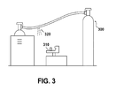
- FIGS. 3 and 4 are directed to an embodiment of the present invention in which the ultrasonic detector is placed in a remotely located position next to a reservoir, e.g., a tank 300, of compressed gas to monitor whether there is a leak 320.
- a reservoir e.g., a tank 300
- FIGS. 3 and 4 are directed to an embodiment of the present invention in which the ultrasonic detector is placed in a remotely located position next to a reservoir, e.g., a tank 300, of compressed gas to monitor whether there is a leak 320.
- FIG. 4 is a block diagram illustrating a system 1500 in which the ultrasonic detector are used for remote monitoring of gas reservoirs.
- the system 1500 includes a plurality of ultrasonic detectors 1520, 1530, 1540, 1550, 1560, 1570 located at respective gas reservoirs.
- the ultrasonic detectors 1520 ... 1570 detect ultrasonic emissions generated by leaks of compressed gas, and heterodyne the ultrasonic emissions into audio signals proportional to the received ultrasonic emissions. While six ultrasonic detectors 1520 ... 1570 are shown, any number of ultrasonic detectors may be included in the system.
- the ultrasonic detectors 1520 ... 1570 include respective failure condition detectors 1521, 1531, 1541, 1551, 1561, 1571, which can in real-time detect a potential leak condition when the audio signal falls outside of a predetermined profile.
- Digital audio network converters 1522, 1532, 1542, 1552, 1562, 1572 convert the audio signal into a digital audio stream, which is transmitted via an Ethernet connection (not shown) in either half or full duplex mode.
- the converters 1522 ... 1572 and the failure condition detectors 1521 ... 1571 may be located with the ultrasonic detectors 1520 ... 1570 or they may be provided in separate housings.
- a user is able to set the IP address of the digital audio network converter 1522 ... 1572 for use in single point-to-point systems or for use in multiple detector systems using LAN networks or router-based systems.
- the digital audio stream can be generated and transmitted continuously, only when a potential leak condition is detected, at periodic intervals for regular testing, or anytime testing of a compressed gas reservoir is desired. Also, the user can start and stop the digital audio stream using control signals transmitted via the Ethernet connection to the ultrasonic detector 1520 ... 1570.
- a processing unit 1510 is centrally located remotely to receive inputs from the ultrasonic detectors 1520 ... 1570. Transmitting lines 1523, 1533, 1543, 1553, 1563, 1573 transmit the digital audio stream to the processing unit 1510. Thus, it is not merely an alarm signal that is sent to the central processing unit 1510, but a digitized version of the audio frequency signal that is representative of the ultrasonic emissions.
- the transmitting lines 1523 ... 1573 can be "hard wired” (e.g., Ethernet, cable, internet, etc.) or wireless (e.g., radio spectrum, Wi-Fi, cell phone, etc.).
- the ultrasonic detectors 1520 ... 1570 as well as the processing unit 1510, can have an embedded local internet server for remote network web browser access/monitoring. Also, when a failure condition is detected by the failure condition detector 1521 ... 1571, an e-mail can be sent to the central processing unit 1510 or any other address.
- an expert can use the processing unit 1510 to analyze the digital audio stream to determine whether the potential failure condition is an actual failure condition or is caused by a false event, such as a competing source. That is, the processing unit 1510 can use analysis software to determine whether the signal represents an actual compressed gas leak. This can be based on the frequency spectrum of the signal. Also, the inspectors can simultaneously hear the digital audio stream while viewing the streams on a screen. When compared with a known "good” or "normal” profile, an anomaly can be quickly determined.
- FIG. 5 is a flowchart 1700 illustrating the operation of the remote monitoring of the compressed gas reservoirs.
- an ultrasonic detector 1520 ... 1570 detects ultrasonic emissions generated by the leaking gas (step 1710).
- the ultrasonic detector 1520 ... 1570 then heterodynes the ultrasonic emissions into an audio signal (step 1720).
- the failure condition detector 1521 ... 1571 detects a potential failure condition when the audio signal falls outside of a predetermined profile (step 1730).
- a potential failure condition i.e., a leak of compressed gas
- the audio signal is digitized to create a digital audio stream (step 1740).
- the digital audio stream is then transmitted to the central processing unit 1510 located remotely from the gas reservoir at the ultrasonic detector 1520 ... 1570 (step 1750).
- the processing unit 1510 analyzes the digital audio stream to determine whether the potential failure condition is an actual failure condition (step 1760). If there is an actual failure condition, the processing unit 1510 could send a control signal to the gas reservoir to shut down its operation.
- the processor 1510 can analyze the signal to determine the rate of flow of the leak, and in turn calculate the amount of electrical energy per unit time it would take to replace the leaking gas, as well as the carbon footprint or carbon load created by the replacement of the leaking gas.
- FIG. 6 is a graph of a set of curves which shows the relationship between flow rate in cubic feet per minute (cfm) and the ultrasonic signal amplitude in decibel (dB) level for leaks of compressed gas at specific pressure levels.
- the values in the flow rate table were empirically determined and statistically trended for the best fit relationships. Since at least the initial set gas pressure is known for any gas reservoir at a facility, the flow rate can be determined rather accurately. Naturally, if the leak persists over a long period of time or is at an exceptionally high rate, the gas pressure will drop and the flow rate calculation will be somewhat less accurate.
- the values in FIG. 6 can be programmed into the processor 1510 of FIG. 4 , so that for each detector 1520 ... 1570, the processor can calculate the flow rate of any leak detected by it.
- This flow rate can be displayed on the monitor of processor 1510 so that an operator can immediately see the rate of gas leakage at one or all of the gas reservoirs of a facility, and can make operational decisions as a result thereof. Such decisions can include anything from ignoring the leak because it is too small to be significant to halting the operation of the facility
- ultrasonic detectors By centralizing the calculation of the flow rate of the leak, as well as the information that can be determined from it, e.g., electricity cost and carbon footprint, commercially available ultrasonic detectors, e.g., the UE System's UltraProbeTM series of instruments, can be used to carry out the invention without modification. However, it is also contemplated that the software and computing power for making these determinations could be incorporated into individual ultrasonic detectors.
- One piece of information provided by the present invention that the operator of the facility may find helpful is an estimate of how much money can be saved annually (cost avoidance) by identifying and repairing leaks on a compressed air system.
- Another piece of useful information is an estimate of the "emission footprint,” specifically the carbon footprint (in pounds of carbon dioxide) and the other significant components of the emission footprint created by using electricity to generate compressed air in a compressed gas system that leaks.
- Carbon dioxide, nitrogen oxide, and sulfur dioxide are the most significant components of the products of combustion when generating electricity from burning fossil fuels. Emission coefficients are calculated and tabulated by state in the State Electricity Profiles Report from the US Department of Energy, Energy Information Administration Office of Coal, Nuclear, Electric, and Alternative Fuels in terms of Pounds of carbon dioxide per kilo Watt hour (lbs of CO 2 /hWh), Pounds nitrogen oxide per kilo Watt hour (lbs of NO/kWh), and pounds of sulfur dioxide per kilo Watt hour (lbs of SO 2 /kWh) This information can also be stored in processor 1510 and used to make the desired calculations.
- the Compressed Gas Survey information of FIG 6 converts the dB level of the ultrasonic leak to a flow rate (cfm) and the Electricity Profiles Report information is used to calculate the cost to generate 1000 cubic feet of air (MCF).
- MCF cubic feet of air
- the system calculates the cost of the air leaks (cost avoidance) and the emission footprint in lbs of CO 2 , NO, and SO 2 for the facility with the leaks that are not repaired for a specified operation time.
- an ultrasonic detector e.g., an UltraprobeTM is used to measure the ultrasonic dB (decibel) level of a pressurized air leak or leaks. This information is used to calculate the cost of electricity, either at the detector, or a remote processor 1510.
- a Cost Interface as shown in FIG. 7 , is accessed by the user. This interface is used to enter the costs for gases for the year. At location 710 the year, e.g., 2008, is inserted.
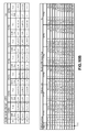
- the user can choose the state from the drop down list at 720 and enter the cost of electricity at 730 to automatically calculate the cost of an air leak per 1000 cubic feet (e.g., $0.33) and to enable the generation of environmental impact estimations. If the state/region is not listed, the user can select "Other” and complete the blank cells at the top of the Coefficient Table of FIG. 11 .
- FIG. 11 is a State Electricity Coefficients chart which lists this information by state.
- Column 1101 lists the names of the states.
- Column 1102 indicates the net electrical power generation of each state.
- the sulfur dioxide, nitrogen oxide and carbon dioxide emitted from the electrical generating capacity in the state are listed in 1000 metric ton units.
- Columns 1106-1108 provide the same information in pounds.
- Columns 1109-1111 indicate the emission efficiency for each gas, i.e., the mass of the gas divided by the total electrical generation in terms of kWh.
- the user can enter his or her cost for 1000 cubic feet of air and manually enter the Argon, Helium, Hydrogen and Nitrogen costs in the state. Changing these values updates the entire electronic spreadsheet.
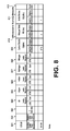
- the Report Worksheet screen of FIG. 8 is used to tabulate all of the leaks found for the year.
- the first column 801 identifies the cost of the leak, i.e., the expense that can be avoided if the leak is repaired.
- the next column 802 provides the cost savings for leaks that were repaired.
- Column 803 gives the percentage of leaks that have been repaired.
- the columns 804-808 list the flow rate of the detected leak and the cost of each gas.
- the next columns 809-811 are for the identified and realized avoidance for carbon dioxide, nitric oxide and sulfur dioxide, respectively.
- the last column, the "Focus Area" 812 is the location of leak. Below the listings there is a space reserved for notes.
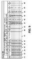
- the first six columns 910, 920, 930, 940, 950, 960 of FIG. 9 indicate the number of the record, the Group Name (e.g., Air Leaks for May), the location of the compressed gas reservoir, the type of gas, the pressure and the dB reading from the ultrasonic detector at that location.
- the type of gas and the gas pressure can be input by means of drop down menus. Drop down menus can be also used to assist in making other entries.
- next column 970.
- the operator can indicate whether the leak has been repaired and the work order schedule number for the leak.
- the next two columns 991, 992 indicate the amount saved by fixing the leak and the size of the leak. This is calculated from the dB reading and the pressure, according to the information in the chart of FIG. 6 .
- the energy in kilowatt hours (kWh) is indicated in column 993.
- the amount of CO 2 , NO and SO 2 emissions eliminated by repair of the leak are indicated in the last three columns, 994, 995, 996 for compressed air only.
- FIG. 9 there is a summary of the input information. It provides the flow rate and cost of all leaks repaired, as well as similar information for each of the gases. The last entries provide information on the leaks identified, repaired and the percentage complete.
- the dB measurement is converted into a flow rate according to the chart of FIG. 6 and an associated "cost avoidance in $" of that leak for a specific pressure and for the entered operational time is calculated.
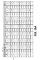
- FIG. 10A the dB reading is provided in column 1001.
- the corresponding leak rate is provided in column 1002 and the cost is provided in column 1003 for gas at a pressure of 150 pounds-per-square inch (psi).
- FIG. 10A provides values for increasing dB readings and for different pressures.
- the gas is compressed Air.
- FIG 10B shows the end of the chart which begins in FIG. 10A , as well as a table 1020 which provides correspondence between a leak rate, the diameter of the leak and the costs for different pressures.
- the total kilo Watt hours (kWh) required to run the compressors and to maintain the pressure given the measured leak or leaks for the entered operational time is calculated by dividing the "cost avoidance in $" by the cost of electricity in $/kWh.
- the total pounds (lbs) of CO 2 , NO, and SO 2 generated (the emission footprint) for a specific operational time to run and maintain a pressure in a compressed air system with the identified leak or leaks is calculated by multiplying the Emission coefficients for CO 2 , NO, and SO 2 (lbs/kWh) by the total Kilo Watt Hours (kWh.
- the value of individual leaks can be determined in terms of electrical usage, cost of electricity and/or carbon emissions. Further, the user can track value of the total of all leaks in a facility or over an entire enterprise. Further, any trends can also be determined.
- the process can be automated to produce reports based on the dB output of ultrasonic detection instruments. Such reports may be web based so that individual and total results for a site, a division or an enterprise can be tracked remotely. In particular, remote access to processor 1510 can be provided over a private network or the internet. In addition, if industry averages may be posted by processor 1510 so that a company can track its performance versus a baseline average.
Landscapes
- Physics & Mathematics (AREA)
- General Physics & Mathematics (AREA)
- Immunology (AREA)
- Biochemistry (AREA)
- Pathology (AREA)
- Health & Medical Sciences (AREA)
- Life Sciences & Earth Sciences (AREA)
- Chemical & Material Sciences (AREA)
- Analytical Chemistry (AREA)
- Signal Processing (AREA)
- General Health & Medical Sciences (AREA)
- Engineering & Computer Science (AREA)
- Mathematical Physics (AREA)
- Spectroscopy & Molecular Physics (AREA)
- Acoustics & Sound (AREA)
- Examining Or Testing Airtightness (AREA)
Claims (26)
- Système destiné à déterminer l'empreinte carbone d'une fuite de gaz comprimé à partir d'une alimentation en gaz comprimé créée par un compresseur électrique connecté à un réseau de génération d'alimentation électrique, le système comprenant : un détecteur à ultrasons configuré pour détecter l'existence et le volume d'une fuite de gaz comprimé et pour générer un signal électrique représentatif de celui-ci, un dispositif de mémorisation configuré pour mémoriser des informations sur le type de gaz comprimé, l'efficacité du compresseur créant le gaz comprimé et les émissions de carbone nécessaires pour que le système de génération électrique qui entraîne le compresseur génère une unité d'électricité, une unité de traitement connectée pour recevoir le signal électrique et ayant accès audit dispositif de mémorisation, ladite unité de traitement incluant un module logiciel configuré pour déterminer une quantité d'énergie électrique par unité de temps nécessaire pour recharger une perte de gaz comprimé qui résulte de la fuite de gaz comprimé déterminée sur la base de l'efficacité du compresseur, et un dispositif d'affichage connecté à l'unité de traitement et configuré pour afficher la quantité d'énergie électrique associée à la fuite de gaz comprimé.
- Système selon la revendication 1, incluant en outre un module logiciel configuré pour calculer les émissions de carbone créées par la quantité d'énergie électrique nécessaire pour recharger la perte de gaz comprimé.
- Système selon la revendication 2, dans lequel le dispositif d'affichage est en outre configuré pour afficher la quantité d'émissions de carbone.
- Système selon la revendication 1 dans lequel le détecteur à ultrasons comprend : un circuit hétérodyne configuré pour transformer un signal ultrasonore en un signal audio, un dispositif d'affichage configuré pour afficher une représentation à séries temporelles du signal ultrasonore hétérodyne, une prise pour casque, un détecteur d'état de panne en communication avec le circuit hétérodyne et configuré pour déterminer si le signal audio se trouve en dehors d'un profil prédéterminé, un convertisseur de réseau audio numérique configuré pour convertir un signal audio en dehors de la plage prédéterminée en un flux de données numériques et pour transmettre le flux de données numériques sous la forme d'un signal électrique représentatif de l'existence et du volume d'une fuite de gaz comprimé.
- Système selon la revendication 4 dans lequel ledit convertisseur de réseau audio numérique est configuré pour transmettre le flux de données numériques sur un réseau de communication, et ladite unité de traitement est connectée au réseau de communication et inclut un module logiciel d'analyse configuré pour déterminer si le flux de données numériques représente une fuite de gaz comprimé, et pour déterminer le débit de la fuite de gaz comprimé déterminée de manière à calculer une quantité d'énergie électrique par unité de temps nécessaire pour recharger une perte de gaz comprimé qui résulte de la fuite de gaz comprimé déterminée, l'unité de traitement incluant en outre un module logiciel configuré pour calculer l'empreinte carbone créée par la quantité d'énergie électrique nécessaire pour recharger la perte de gaz comprimé.
- Système selon la revendication 5, dans lequel le détecteur à ultrasons est éloigné par rapport à l'unité de traitement et à proximité d'un réservoir de gaz comprimé.
- Système selon la revendication 5, dans lequel le détecteur à ultrasons, le détecteur d'état de panne, et le convertisseur de réseau audio numérique sont situés dans un seul boitier.
- Système selon la revendication 5, dans lequel la quantité calculée d'énergie électrique dépend de facteurs incluant au moins l'un d'un type particulier de gaz devant être comprimé, et d'une efficacité du compresseur de gaz connecté au réservoir.
- Système selon la revendication 5, dans lequel l'empreinte carbone calculée dépend d'un type de génération d'alimentation électrique.
- Système selon la revendication 5, comprenant en outre une pluralité de détecteurs à ultrasons situés à proximité d'une pluralité de réservoirs respectifs de gaz comprimé, dans lequel chaque détecteur de la pluralité de détecteurs à ultrasons est connecté à un détecteur d'état de panne respectif.
- Système selon la revendication 10, dans lequel l'unité de traitement reçoit des flux de données numériques respectifs représentatifs d'un signal ultrasonore provenant de chaque détecteur de la pluralité de détecteurs à ultrasons, le système comprenant en outre un dispositif d'affichage connecté à l'unité de traitement, dans lequel le dispositif d'affichage est configuré pour afficher au moins l'une d'une quantité cumulée d'énergie électrique nécessaire pour recharger la pluralité de réservoirs respectifs et d'une empreinte carbone cumulée correspondant à la quantité cumulée d'énergie électrique.
- Système selon la revendication 5, dans lequel l'unité de traitement est en outre configurée pour générer un rapport corrélant au moins l'un d'une fuite de gaz comprimé déterminée avec une utilisation d'électricité, d'un coup d'utilisation d'électricité par unité de temps, et d'une quantité d'émissions de carbone nécessaires pour recharger la perte de gaz comprimé.
- Système selon la revendication 5, dans lequel le convertisseur de réseau audio numérique est configuré pour générer le flux audio numérique soit de manière continue, soit de manière périodique, et soit en réponse à une détection d'une fuite de gaz comprimé potentielle.
- Système selon la revendication 5, dans lequel le détecteur de fuite à ultrasons inclut en outre un serveur réseau incorporé pour un accès et une surveillance à distance.
- Système selon la revendication 5, dans lequel la détermination par l'unité de traitement d'une fuite de gaz comprimé est basée sur un spectre de fréquences du flux de données numériques reçu.
- Procédé destiné à surveiller à distance des fuites de gaz potentielles à partir d'un réservoir de gaz comprimé créé par un compresseur électrique connecté à un réseau de génération d'alimentation électrique et destiné à déterminer l'empreinte carbone à la suite d'une telle fuite, le procédé comprenant les étapes consistant à : détecter des émissions ultrasonores à partir du réservoir de gaz comprimé dues à une fuite de gaz, générer un signal électrique représentatif de l'existence et du volume par unité de temps de la fuite de gaz, mémoriser des informations sur le type de gaz comprimé, l'efficacité du compresseur créant le gaz comprimé et les émissions de carbone nécessaires pour que le système de génération électrique qui entraîne le compresseur génère une unité d'électricité, et calculer une quantité d'énergie électrique par unité de temps nécessaire pour recharger une perte de gaz comprimé résultant de la fuite de gaz, ledit calcul étant basé sur l'efficacité du compresseur.
- Procédé selon la revendication 16 incluant en outre l'étape consistant à calculer l'empreinte carbone créée par la fuite de gaz sur la base des émissions de carbone nécessaires pour que le système de génération d'alimentation électrique qui entraîne le compresseur génère une unité d'électricité.
- Procédé selon la revendication 16 dans lequel les étapes consistant à détecter des émissions ultrasonores et à générer un signal électrique comprennent les étapes consistant à : générer un signal électrique ultrasonore sur la base des émissions ultrasonores provenant de la fuite de gaz comprimé, transformer de façon hétérodyne le signal ultrasonore en un signal audio, fournir le signal audio à un détecteur d'état de panne qui détermine si le signal audio se trouve en dehors d'un profil prédéterminé, numériser, au moyen d'un convertisseur de réseau audio numérique, un signal audio en dehors de la plage prédéterminée en un flux de données numériques, déterminer avec un dispositif de traitement, si le flux de données numériques représente une fuite de gaz comprimé, calculer le débit de la fuite de gaz comprimé déterminée, et générer un signal électrique représentatif de l'existence et du volume par unité de temps de la fuite de gaz.
- Procédé selon la revendication 18 incluant en outre les étapes consistant à transmettre le flux de données numériques sur un réseau de communication à une unité de traitement, déterminer, au moyen de l'unité de traitement, si le flux de données numériques représente une fuite de gaz comprimé, calculer une quantité d'énergie électrique par unité de temps nécessaire pour recharger une perte de gaz comprimé qui résulte du débit analysé, et calculer l'empreinte carbone créée par la quantité d'énergie électrique nécessaire pour recharger la perte de gaz comprimé.
- Procédé selon la revendication 19, dans lequel l'unité de traitement est éloignée par rapport au détecteur à ultrasons.
- Procédé selon la revendication 19, dans lequel l'étape de fourniture inclut l'étape consistant à fournir une pluralité de détecteurs à ultrasons à proximité d'une pluralité de réservoirs de gaz comprimé respectifs.
- Procédé selon la revendication 19, incluant en outre l'étape consistant à envoyer un signal de commande à un compresseur couplé au réservoir de gaz comprimé.
- Procédé selon la revendication 19, dans lequel le calcul de la quantité d'énergie électrique est basé sur un ensemble de courbes qui montrent la relation entre le débit et une amplitude des émissions ultrasonores.
- Procédé selon la revendication 19, incluant en outre l'étape consistant à afficher sur un moniteur connecté à l'unité de traitement le débit de la fuite de gaz déterminée.
- Procédé selon la revendication 19, incluant en outre l'étape consistant à fournir une estimation de la réduction des coûts permise par la réparation des fuites de gaz comprimé.
- Procédé selon la revendication 25, dans lequel la réduction des coûts est mesurée avec une unité parmi une unité monétaire et une unité d'empreinte carbone.
Applications Claiming Priority (2)
| Application Number | Priority Date | Filing Date | Title |
|---|---|---|---|
| US5883408P | 2008-06-04 | 2008-06-04 | |
| PCT/US2009/046059 WO2009149140A2 (fr) | 2008-06-04 | 2009-06-03 | Détecteur de fuites de gaz par ultrasons avec une perte de puissance électrique et une sortie d'empreinte carbone |
Publications (3)
| Publication Number | Publication Date |
|---|---|
| EP2283335A2 EP2283335A2 (fr) | 2011-02-16 |
| EP2283335A4 EP2283335A4 (fr) | 2013-08-21 |
| EP2283335B1 true EP2283335B1 (fr) | 2015-09-02 |
Family
ID=41398828
Family Applications (1)
| Application Number | Title | Priority Date | Filing Date |
|---|---|---|---|
| EP09759299.2A Active EP2283335B1 (fr) | 2008-06-04 | 2009-06-03 | Detecteur de fuites de gaz par ultrasons avec une perte de puissance electrique et une sortie d'empreinte carbone |
Country Status (3)
| Country | Link |
|---|---|
| EP (1) | EP2283335B1 (fr) |
| CA (1) | CA2722871C (fr) |
| WO (1) | WO2009149140A2 (fr) |
Families Citing this family (3)
| Publication number | Priority date | Publication date | Assignee | Title |
|---|---|---|---|---|
| US9091613B2 (en) * | 2012-06-27 | 2015-07-28 | General Monitors, Inc. | Multi-spectral ultrasonic gas leak detector |
| DE102014221475A1 (de) | 2014-10-22 | 2016-04-28 | Sonotec Ultraschallsensorik Halle Gmbh | Verfahren und Vorrichtung zur akustischen Messung von Austrittsgeschwindigkeiten und/oder Austrittsvolumenströmen von Gasen oder Flüssigkeiten |
| DE102023117154A1 (de) * | 2023-06-29 | 2025-01-02 | Boge Kompressoren Otto Boge Gmbh & Co. Kg | Verfahren und Einrichtung zur Erfassung und Anzeige von Leckageverlusten einer Druckluftanlage |
Family Cites Families (6)
| Publication number | Priority date | Publication date | Assignee | Title |
|---|---|---|---|---|
| JPH0614381B2 (ja) * | 1986-04-15 | 1994-02-23 | 株式会社テイエルブイ | 複数のスチームトラップの蒸気漏れデータの自動集計分析装置 |
| GB2204403B (en) * | 1987-05-05 | 1991-07-17 | David John Howard Peacock | "method of detecting leaks" |
| US5103675A (en) * | 1989-12-20 | 1992-04-14 | Komninos Nikolaos I | Signal detector and method for detecting signals having selected frequency characteristics |
| US5719785A (en) * | 1994-05-17 | 1998-02-17 | Standifer; Larry R. | Detection and quantification of fluid leaks |
| JPH11142279A (ja) * | 1997-11-07 | 1999-05-28 | Mec:Kk | 超音波式漏れ検査装置 |
| JP4968668B2 (ja) * | 2006-06-15 | 2012-07-04 | エイトシステム株式会社 | ハウジングなどの漏れ検査装置 |
-
2009
- 2009-06-03 EP EP09759299.2A patent/EP2283335B1/fr active Active
- 2009-06-03 WO PCT/US2009/046059 patent/WO2009149140A2/fr not_active Ceased
- 2009-06-03 CA CA2722871A patent/CA2722871C/fr active Active
Also Published As
| Publication number | Publication date |
|---|---|
| CA2722871C (fr) | 2016-08-09 |
| WO2009149140A2 (fr) | 2009-12-10 |
| EP2283335A4 (fr) | 2013-08-21 |
| WO2009149140A3 (fr) | 2010-02-25 |
| EP2283335A2 (fr) | 2011-02-16 |
| CA2722871A1 (fr) | 2009-12-10 |
Similar Documents
| Publication | Publication Date | Title |
|---|---|---|
| US7817050B2 (en) | Ultrasonic gas leak detector with an electrical power loss and carbon footprint output | |
| CN101761780B (zh) | 输气管道泄漏检测定位装置及其检测定位方法 | |
| ES2839250T3 (es) | Sistema de gestión de datos de fugas de fluidos | |
| US10386261B2 (en) | High repetition rate thermometry system and method | |
| US20090007968A1 (en) | Pipe network, with a hierarchical structure, for supplying water or gas and/or for removing industrial water, process for detecting a leak in such a pipe network and process for determining, with the aid of a computer, the operating life theoretically remaining for a renewable power source for at least one flowmeter in such a pipe network | |
| JP4390625B2 (ja) | 漏水監視装置 | |
| US5719785A (en) | Detection and quantification of fluid leaks | |
| US10184611B2 (en) | Detecting fluid properties of a multiphase flow in a condensate drain | |
| Çağman et al. | A research on the easy-to-use energy efficiency performance indicators for energy audit and energy monitoring of industrial compressed air systems | |
| CN116862253A (zh) | 一种多源数据碳排放评价方法及装置 | |
| EP2283335B1 (fr) | Detecteur de fuites de gaz par ultrasons avec une perte de puissance electrique et une sortie d'empreinte carbone | |
| JPH0896039A (ja) | 水道管路情報管理装置 | |
| CN118443251A (zh) | 一种振动台运行性能全状态监测评估系统及方法 | |
| CN102830210A (zh) | 全自动在线可组态水环境监测仪检定装置 | |
| GB2459319A (en) | Calculating steam loss by comparison of a vibration signal to a previously generated record that correlates vibration and leakage quantity | |
| US6804992B2 (en) | System and method for processing ultrasonic signals | |
| KR101387672B1 (ko) | 센서의 건전성 평가장치 | |
| EP3875919B1 (fr) | Surveillance de la santé d'un compteur de gaz rotatif | |
| JP4942191B2 (ja) | 騒音源の影響度解析システム | |
| CN117169447B (zh) | 一种排污管道清洁检测方法及检测装置 | |
| CN106353036B (zh) | 用于检测压缩空气系统泄露的方法 | |
| Bandes | Ultrasonic condition monitoring | |
| CN114484292A (zh) | 一种可燃气体监测装置和方法 | |
| KR20060109543A (ko) | 이동통신 단말기를 이용한 환경 오염도 측정 및 관리시스템 | |
| JP4950603B2 (ja) | プラント用圧力伝送器点検システム |
Legal Events
| Date | Code | Title | Description |
|---|---|---|---|
| PUAI | Public reference made under article 153(3) epc to a published international application that has entered the european phase |
Free format text: ORIGINAL CODE: 0009012 |
|
| 17P | Request for examination filed |
Effective date: 20101118 |
|
| AK | Designated contracting states |
Kind code of ref document: A2 Designated state(s): AT BE BG CH CY CZ DE DK EE ES FI FR GB GR HR HU IE IS IT LI LT LU LV MC MK MT NL NO PL PT RO SE SI SK TR |
|
| AX | Request for extension of the european patent |
Extension state: AL BA RS |
|
| DAX | Request for extension of the european patent (deleted) | ||
| A4 | Supplementary search report drawn up and despatched |
Effective date: 20130719 |
|
| RIC1 | Information provided on ipc code assigned before grant |
Ipc: G01M 3/24 20060101AFI20130715BHEP Ipc: G01N 29/46 20060101ALI20130715BHEP Ipc: G06Q 50/06 20120101ALI20130715BHEP Ipc: G01N 29/14 20060101ALI20130715BHEP |
|
| GRAP | Despatch of communication of intention to grant a patent |
Free format text: ORIGINAL CODE: EPIDOSNIGR1 |
|
| RIC1 | Information provided on ipc code assigned before grant |
Ipc: G01N 29/14 20060101ALI20141203BHEP Ipc: G06Q 10/00 20120101ALI20141203BHEP Ipc: G06Q 50/06 20120101ALI20141203BHEP Ipc: G01N 29/46 20060101ALI20141203BHEP Ipc: G01M 3/24 20060101AFI20141203BHEP |
|
| INTG | Intention to grant announced |
Effective date: 20150105 |
|
| GRAP | Despatch of communication of intention to grant a patent |
Free format text: ORIGINAL CODE: EPIDOSNIGR1 |
|
| INTG | Intention to grant announced |
Effective date: 20150413 |
|
| RIN1 | Information on inventor provided before grant (corrected) |
Inventor name: MOHR, GARY Inventor name: GOODMAN, MARK, A. Inventor name: BISHOP, WILLIAM |
|
| GRAS | Grant fee paid |
Free format text: ORIGINAL CODE: EPIDOSNIGR3 |
|
| GRAA | (expected) grant |
Free format text: ORIGINAL CODE: 0009210 |
|
| AK | Designated contracting states |
Kind code of ref document: B1 Designated state(s): AT BE BG CH CY CZ DE DK EE ES FI FR GB GR HR HU IE IS IT LI LT LU LV MC MK MT NL NO PL PT RO SE SI SK TR |
|
| REG | Reference to a national code |
Ref country code: GB Ref legal event code: FG4D |
|
| REG | Reference to a national code |
Ref country code: AT Ref legal event code: REF Ref document number: 746919 Country of ref document: AT Kind code of ref document: T Effective date: 20150915 Ref country code: CH Ref legal event code: EP |
|
| REG | Reference to a national code |
Ref country code: IE Ref legal event code: FG4D |
|
| REG | Reference to a national code |
Ref country code: DE Ref legal event code: R096 Ref document number: 602009033365 Country of ref document: DE |
|
| REG | Reference to a national code |
Ref country code: AT Ref legal event code: MK05 Ref document number: 746919 Country of ref document: AT Kind code of ref document: T Effective date: 20150902 |
|
| PG25 | Lapsed in a contracting state [announced via postgrant information from national office to epo] |
Ref country code: NO Free format text: LAPSE BECAUSE OF FAILURE TO SUBMIT A TRANSLATION OF THE DESCRIPTION OR TO PAY THE FEE WITHIN THE PRESCRIBED TIME-LIMIT Effective date: 20151202 Ref country code: LV Free format text: LAPSE BECAUSE OF FAILURE TO SUBMIT A TRANSLATION OF THE DESCRIPTION OR TO PAY THE FEE WITHIN THE PRESCRIBED TIME-LIMIT Effective date: 20150902 Ref country code: LT Free format text: LAPSE BECAUSE OF FAILURE TO SUBMIT A TRANSLATION OF THE DESCRIPTION OR TO PAY THE FEE WITHIN THE PRESCRIBED TIME-LIMIT Effective date: 20150902 Ref country code: GR Free format text: LAPSE BECAUSE OF FAILURE TO SUBMIT A TRANSLATION OF THE DESCRIPTION OR TO PAY THE FEE WITHIN THE PRESCRIBED TIME-LIMIT Effective date: 20151203 Ref country code: FI Free format text: LAPSE BECAUSE OF FAILURE TO SUBMIT A TRANSLATION OF THE DESCRIPTION OR TO PAY THE FEE WITHIN THE PRESCRIBED TIME-LIMIT Effective date: 20150902 |
|
| REG | Reference to a national code |
Ref country code: NL Ref legal event code: FP |
|
| REG | Reference to a national code |
Ref country code: LT Ref legal event code: MG4D |
|
| PG25 | Lapsed in a contracting state [announced via postgrant information from national office to epo] |
Ref country code: AT Free format text: LAPSE BECAUSE OF FAILURE TO SUBMIT A TRANSLATION OF THE DESCRIPTION OR TO PAY THE FEE WITHIN THE PRESCRIBED TIME-LIMIT Effective date: 20150902 Ref country code: PL Free format text: LAPSE BECAUSE OF FAILURE TO SUBMIT A TRANSLATION OF THE DESCRIPTION OR TO PAY THE FEE WITHIN THE PRESCRIBED TIME-LIMIT Effective date: 20150902 Ref country code: ES Free format text: LAPSE BECAUSE OF FAILURE TO SUBMIT A TRANSLATION OF THE DESCRIPTION OR TO PAY THE FEE WITHIN THE PRESCRIBED TIME-LIMIT Effective date: 20150902 Ref country code: SE Free format text: LAPSE BECAUSE OF FAILURE TO SUBMIT A TRANSLATION OF THE DESCRIPTION OR TO PAY THE FEE WITHIN THE PRESCRIBED TIME-LIMIT Effective date: 20150902 |
|
| PG25 | Lapsed in a contracting state [announced via postgrant information from national office to epo] |
Ref country code: CZ Free format text: LAPSE BECAUSE OF FAILURE TO SUBMIT A TRANSLATION OF THE DESCRIPTION OR TO PAY THE FEE WITHIN THE PRESCRIBED TIME-LIMIT Effective date: 20150902 Ref country code: SK Free format text: LAPSE BECAUSE OF FAILURE TO SUBMIT A TRANSLATION OF THE DESCRIPTION OR TO PAY THE FEE WITHIN THE PRESCRIBED TIME-LIMIT Effective date: 20150902 Ref country code: EE Free format text: LAPSE BECAUSE OF FAILURE TO SUBMIT A TRANSLATION OF THE DESCRIPTION OR TO PAY THE FEE WITHIN THE PRESCRIBED TIME-LIMIT Effective date: 20150902 Ref country code: IS Free format text: LAPSE BECAUSE OF FAILURE TO SUBMIT A TRANSLATION OF THE DESCRIPTION OR TO PAY THE FEE WITHIN THE PRESCRIBED TIME-LIMIT Effective date: 20160102 Ref country code: IT Free format text: LAPSE BECAUSE OF FAILURE TO SUBMIT A TRANSLATION OF THE DESCRIPTION OR TO PAY THE FEE WITHIN THE PRESCRIBED TIME-LIMIT Effective date: 20150902 |
|
| REG | Reference to a national code |
Ref country code: FR Ref legal event code: PLFP Year of fee payment: 8 |
|
| PG25 | Lapsed in a contracting state [announced via postgrant information from national office to epo] |
Ref country code: RO Free format text: LAPSE BECAUSE OF FAILURE TO SUBMIT A TRANSLATION OF THE DESCRIPTION OR TO PAY THE FEE WITHIN THE PRESCRIBED TIME-LIMIT Effective date: 20150902 Ref country code: PT Free format text: LAPSE BECAUSE OF FAILURE TO SUBMIT A TRANSLATION OF THE DESCRIPTION OR TO PAY THE FEE WITHIN THE PRESCRIBED TIME-LIMIT Effective date: 20160104 |
|
| REG | Reference to a national code |
Ref country code: DE Ref legal event code: R097 Ref document number: 602009033365 Country of ref document: DE |
|
| PLBE | No opposition filed within time limit |
Free format text: ORIGINAL CODE: 0009261 |
|
| STAA | Information on the status of an ep patent application or granted ep patent |
Free format text: STATUS: NO OPPOSITION FILED WITHIN TIME LIMIT |
|
| 26N | No opposition filed |
Effective date: 20160603 |
|
| PG25 | Lapsed in a contracting state [announced via postgrant information from national office to epo] |
Ref country code: SI Free format text: LAPSE BECAUSE OF FAILURE TO SUBMIT A TRANSLATION OF THE DESCRIPTION OR TO PAY THE FEE WITHIN THE PRESCRIBED TIME-LIMIT Effective date: 20150902 Ref country code: DK Free format text: LAPSE BECAUSE OF FAILURE TO SUBMIT A TRANSLATION OF THE DESCRIPTION OR TO PAY THE FEE WITHIN THE PRESCRIBED TIME-LIMIT Effective date: 20150902 |
|
| PG25 | Lapsed in a contracting state [announced via postgrant information from national office to epo] |
Ref country code: MC Free format text: LAPSE BECAUSE OF FAILURE TO SUBMIT A TRANSLATION OF THE DESCRIPTION OR TO PAY THE FEE WITHIN THE PRESCRIBED TIME-LIMIT Effective date: 20150902 |
|
| REG | Reference to a national code |
Ref country code: CH Ref legal event code: PL |
|
| REG | Reference to a national code |
Ref country code: IE Ref legal event code: MM4A |
|
| PG25 | Lapsed in a contracting state [announced via postgrant information from national office to epo] |
Ref country code: LI Free format text: LAPSE BECAUSE OF NON-PAYMENT OF DUE FEES Effective date: 20160630 Ref country code: CH Free format text: LAPSE BECAUSE OF NON-PAYMENT OF DUE FEES Effective date: 20160630 |
|
| REG | Reference to a national code |
Ref country code: FR Ref legal event code: PLFP Year of fee payment: 9 |
|
| PG25 | Lapsed in a contracting state [announced via postgrant information from national office to epo] |
Ref country code: IE Free format text: LAPSE BECAUSE OF NON-PAYMENT OF DUE FEES Effective date: 20160603 |
|
| REG | Reference to a national code |
Ref country code: FR Ref legal event code: PLFP Year of fee payment: 10 |
|
| PG25 | Lapsed in a contracting state [announced via postgrant information from national office to epo] |
Ref country code: HU Free format text: LAPSE BECAUSE OF FAILURE TO SUBMIT A TRANSLATION OF THE DESCRIPTION OR TO PAY THE FEE WITHIN THE PRESCRIBED TIME-LIMIT; INVALID AB INITIO Effective date: 20090603 Ref country code: CY Free format text: LAPSE BECAUSE OF FAILURE TO SUBMIT A TRANSLATION OF THE DESCRIPTION OR TO PAY THE FEE WITHIN THE PRESCRIBED TIME-LIMIT Effective date: 20150902 |
|
| PG25 | Lapsed in a contracting state [announced via postgrant information from national office to epo] |
Ref country code: HR Free format text: LAPSE BECAUSE OF FAILURE TO SUBMIT A TRANSLATION OF THE DESCRIPTION OR TO PAY THE FEE WITHIN THE PRESCRIBED TIME-LIMIT Effective date: 20150902 Ref country code: MT Free format text: LAPSE BECAUSE OF NON-PAYMENT OF DUE FEES Effective date: 20160630 Ref country code: LU Free format text: LAPSE BECAUSE OF NON-PAYMENT OF DUE FEES Effective date: 20160603 Ref country code: TR Free format text: LAPSE BECAUSE OF FAILURE TO SUBMIT A TRANSLATION OF THE DESCRIPTION OR TO PAY THE FEE WITHIN THE PRESCRIBED TIME-LIMIT Effective date: 20150902 Ref country code: MK Free format text: LAPSE BECAUSE OF FAILURE TO SUBMIT A TRANSLATION OF THE DESCRIPTION OR TO PAY THE FEE WITHIN THE PRESCRIBED TIME-LIMIT Effective date: 20150902 |
|
| PG25 | Lapsed in a contracting state [announced via postgrant information from national office to epo] |
Ref country code: BG Free format text: LAPSE BECAUSE OF FAILURE TO SUBMIT A TRANSLATION OF THE DESCRIPTION OR TO PAY THE FEE WITHIN THE PRESCRIBED TIME-LIMIT Effective date: 20150902 |
|
| PGFP | Annual fee paid to national office [announced via postgrant information from national office to epo] |
Ref country code: NL Payment date: 20250520 Year of fee payment: 17 |
|
| PGFP | Annual fee paid to national office [announced via postgrant information from national office to epo] |
Ref country code: DE Payment date: 20250520 Year of fee payment: 17 |
|
| PGFP | Annual fee paid to national office [announced via postgrant information from national office to epo] |
Ref country code: GB Payment date: 20250520 Year of fee payment: 17 |
|
| PGFP | Annual fee paid to national office [announced via postgrant information from national office to epo] |
Ref country code: BE Payment date: 20250520 Year of fee payment: 17 |
|
| PGFP | Annual fee paid to national office [announced via postgrant information from national office to epo] |
Ref country code: FR Payment date: 20250520 Year of fee payment: 17 |