EP2283346B1 - Calorimètre et procédés d'utilisation et systèmes de commande y afférant - Google Patents
Calorimètre et procédés d'utilisation et systèmes de commande y afférant Download PDFInfo
- Publication number
- EP2283346B1 EP2283346B1 EP09759491.5A EP09759491A EP2283346B1 EP 2283346 B1 EP2283346 B1 EP 2283346B1 EP 09759491 A EP09759491 A EP 09759491A EP 2283346 B1 EP2283346 B1 EP 2283346B1
- Authority
- EP
- European Patent Office
- Prior art keywords
- sensor
- controller
- sample
- temperature
- calorimeter
- Prior art date
- Legal status (The legal status is an assumption and is not a legal conclusion. Google has not performed a legal analysis and makes no representation as to the accuracy of the status listed.)
- Not-in-force
Links
- 238000000034 method Methods 0.000 title claims description 42
- 238000010438 heat treatment Methods 0.000 claims description 51
- 238000001816 cooling Methods 0.000 claims description 23
- 239000010409 thin film Substances 0.000 claims description 21
- 238000003860 storage Methods 0.000 claims description 6
- 239000000523 sample Substances 0.000 description 118
- 238000002425 crystallisation Methods 0.000 description 16
- 230000008025 crystallization Effects 0.000 description 16
- 238000005259 measurement Methods 0.000 description 16
- BASFCYQUMIYNBI-UHFFFAOYSA-N platinum Chemical compound [Pt] BASFCYQUMIYNBI-UHFFFAOYSA-N 0.000 description 16
- 238000002844 melting Methods 0.000 description 15
- 230000008018 melting Effects 0.000 description 15
- 230000006870 function Effects 0.000 description 14
- 230000008569 process Effects 0.000 description 13
- 238000005516 engineering process Methods 0.000 description 11
- 239000007789 gas Substances 0.000 description 11
- 238000004458 analytical method Methods 0.000 description 10
- 238000000113 differential scanning calorimetry Methods 0.000 description 10
- 230000008901 benefit Effects 0.000 description 8
- 238000004891 communication Methods 0.000 description 8
- 229910052697 platinum Inorganic materials 0.000 description 8
- 229920000642 polymer Polymers 0.000 description 8
- 239000000126 substance Substances 0.000 description 8
- PXHVJJICTQNCMI-UHFFFAOYSA-N Nickel Chemical compound [Ni] PXHVJJICTQNCMI-UHFFFAOYSA-N 0.000 description 6
- 238000010586 diagram Methods 0.000 description 6
- 239000012528 membrane Substances 0.000 description 6
- 230000007704 transition Effects 0.000 description 6
- 239000000463 material Substances 0.000 description 5
- 238000012545 processing Methods 0.000 description 5
- 230000004044 response Effects 0.000 description 5
- 238000012360 testing method Methods 0.000 description 5
- XUIMIQQOPSSXEZ-UHFFFAOYSA-N Silicon Chemical compound [Si] XUIMIQQOPSSXEZ-UHFFFAOYSA-N 0.000 description 4
- ATJFFYVFTNAWJD-UHFFFAOYSA-N Tin Chemical compound [Sn] ATJFFYVFTNAWJD-UHFFFAOYSA-N 0.000 description 4
- 238000002474 experimental method Methods 0.000 description 4
- 230000007246 mechanism Effects 0.000 description 4
- 229910052703 rhodium Inorganic materials 0.000 description 4
- 239000010948 rhodium Substances 0.000 description 4
- MHOVAHRLVXNVSD-UHFFFAOYSA-N rhodium atom Chemical compound [Rh] MHOVAHRLVXNVSD-UHFFFAOYSA-N 0.000 description 4
- 229910052710 silicon Inorganic materials 0.000 description 4
- 239000010703 silicon Substances 0.000 description 4
- 241000894007 species Species 0.000 description 4
- 238000012546 transfer Methods 0.000 description 4
- 230000000694 effects Effects 0.000 description 3
- 230000009477 glass transition Effects 0.000 description 3
- 239000002923 metal particle Substances 0.000 description 3
- 229910052759 nickel Inorganic materials 0.000 description 3
- 239000002245 particle Substances 0.000 description 3
- 238000005070 sampling Methods 0.000 description 3
- IJGRMHOSHXDMSA-UHFFFAOYSA-N Atomic nitrogen Chemical compound N#N IJGRMHOSHXDMSA-UHFFFAOYSA-N 0.000 description 2
- VYZAMTAEIAYCRO-UHFFFAOYSA-N Chromium Chemical compound [Cr] VYZAMTAEIAYCRO-UHFFFAOYSA-N 0.000 description 2
- 229910001006 Constantan Inorganic materials 0.000 description 2
- XEEYBQQBJWHFJM-UHFFFAOYSA-N Iron Chemical compound [Fe] XEEYBQQBJWHFJM-UHFFFAOYSA-N 0.000 description 2
- KDLHZDBZIXYQEI-UHFFFAOYSA-N Palladium Chemical compound [Pd] KDLHZDBZIXYQEI-UHFFFAOYSA-N 0.000 description 2
- 239000004743 Polypropylene Substances 0.000 description 2
- 238000004364 calculation method Methods 0.000 description 2
- 230000008859 change Effects 0.000 description 2
- 229910052804 chromium Inorganic materials 0.000 description 2
- 239000011651 chromium Substances 0.000 description 2
- 230000008878 coupling Effects 0.000 description 2
- 238000010168 coupling process Methods 0.000 description 2
- 238000005859 coupling reaction Methods 0.000 description 2
- 239000003814 drug Substances 0.000 description 2
- 239000010408 film Substances 0.000 description 2
- 230000010354 integration Effects 0.000 description 2
- 229910052751 metal Inorganic materials 0.000 description 2
- 239000002184 metal Substances 0.000 description 2
- 238000012544 monitoring process Methods 0.000 description 2
- -1 polypropylene Polymers 0.000 description 2
- 229920001155 polypropylene Polymers 0.000 description 2
- 238000002440 power-compensation differential scanning calorimetry Methods 0.000 description 2
- 238000011160 research Methods 0.000 description 2
- 238000000926 separation method Methods 0.000 description 2
- 238000002076 thermal analysis method Methods 0.000 description 2
- 238000005033 Fourier transform infrared spectroscopy Methods 0.000 description 1
- 238000007792 addition Methods 0.000 description 1
- 239000000853 adhesive Substances 0.000 description 1
- 230000001070 adhesive effect Effects 0.000 description 1
- 230000002411 adverse Effects 0.000 description 1
- 230000004075 alteration Effects 0.000 description 1
- CSDREXVUYHZDNP-UHFFFAOYSA-N alumanylidynesilicon Chemical compound [Al].[Si] CSDREXVUYHZDNP-UHFFFAOYSA-N 0.000 description 1
- 238000013528 artificial neural network Methods 0.000 description 1
- 230000009286 beneficial effect Effects 0.000 description 1
- 238000009529 body temperature measurement Methods 0.000 description 1
- 238000007707 calorimetry Methods 0.000 description 1
- 238000006243 chemical reaction Methods 0.000 description 1
- 239000007795 chemical reaction product Substances 0.000 description 1
- 230000001149 cognitive effect Effects 0.000 description 1
- 239000002131 composite material Substances 0.000 description 1
- 238000010276 construction Methods 0.000 description 1
- 239000002537 cosmetic Substances 0.000 description 1
- 239000013078 crystal Substances 0.000 description 1
- 238000007405 data analysis Methods 0.000 description 1
- 230000003247 decreasing effect Effects 0.000 description 1
- 238000002242 deionisation method Methods 0.000 description 1
- 230000001419 dependent effect Effects 0.000 description 1
- 230000009977 dual effect Effects 0.000 description 1
- 229920001971 elastomer Polymers 0.000 description 1
- 239000000806 elastomer Substances 0.000 description 1
- 239000000835 fiber Substances 0.000 description 1
- 238000001595 flow curve Methods 0.000 description 1
- 239000012530 fluid Substances 0.000 description 1
- 235000013305 food Nutrition 0.000 description 1
- 230000004927 fusion Effects 0.000 description 1
- 238000004868 gas analysis Methods 0.000 description 1
- 238000004817 gas chromatography Methods 0.000 description 1
- 229910052734 helium Inorganic materials 0.000 description 1
- 239000001307 helium Substances 0.000 description 1
- SWQJXJOGLNCZEY-UHFFFAOYSA-N helium atom Chemical compound [He] SWQJXJOGLNCZEY-UHFFFAOYSA-N 0.000 description 1
- 229910010272 inorganic material Inorganic materials 0.000 description 1
- 239000011147 inorganic material Substances 0.000 description 1
- 238000005040 ion trap Methods 0.000 description 1
- 229910052742 iron Inorganic materials 0.000 description 1
- 230000000670 limiting effect Effects 0.000 description 1
- 229910001092 metal group alloy Inorganic materials 0.000 description 1
- 150000002739 metals Chemical class 0.000 description 1
- 230000003278 mimic effect Effects 0.000 description 1
- 238000012986 modification Methods 0.000 description 1
- 230000004048 modification Effects 0.000 description 1
- 229910052757 nitrogen Inorganic materials 0.000 description 1
- 239000011368 organic material Substances 0.000 description 1
- 230000001590 oxidative effect Effects 0.000 description 1
- 229910052763 palladium Inorganic materials 0.000 description 1
- ZONODCCBXBRQEZ-UHFFFAOYSA-N platinum tungsten Chemical compound [W].[Pt] ZONODCCBXBRQEZ-UHFFFAOYSA-N 0.000 description 1
- HWLDNSXPUQTBOD-UHFFFAOYSA-N platinum-iridium alloy Chemical compound [Ir].[Pt] HWLDNSXPUQTBOD-UHFFFAOYSA-N 0.000 description 1
- 238000007639 printing Methods 0.000 description 1
- 239000000047 product Substances 0.000 description 1
- 238000010791 quenching Methods 0.000 description 1
- 230000002829 reductive effect Effects 0.000 description 1
- 239000012925 reference material Substances 0.000 description 1
- 230000008521 reorganization Effects 0.000 description 1
- DECCZIUVGMLHKQ-UHFFFAOYSA-N rhenium tungsten Chemical compound [W].[Re] DECCZIUVGMLHKQ-UHFFFAOYSA-N 0.000 description 1
- 230000035945 sensitivity Effects 0.000 description 1
- 239000012798 spherical particle Substances 0.000 description 1
- 230000003068 static effect Effects 0.000 description 1
- 238000006467 substitution reaction Methods 0.000 description 1
- 238000004781 supercooling Methods 0.000 description 1
- 229920001187 thermosetting polymer Polymers 0.000 description 1
- 230000036962 time dependent Effects 0.000 description 1
Images




Classifications
-
- G—PHYSICS
- G01—MEASURING; TESTING
- G01N—INVESTIGATING OR ANALYSING MATERIALS BY DETERMINING THEIR CHEMICAL OR PHYSICAL PROPERTIES
- G01N25/00—Investigating or analyzing materials by the use of thermal means
- G01N25/20—Investigating or analyzing materials by the use of thermal means by investigating the development of heat, i.e. calorimetry, e.g. by measuring specific heat, by measuring thermal conductivity
- G01N25/48—Investigating or analyzing materials by the use of thermal means by investigating the development of heat, i.e. calorimetry, e.g. by measuring specific heat, by measuring thermal conductivity on solution, sorption, or a chemical reaction not involving combustion or catalytic oxidation
- G01N25/4846—Investigating or analyzing materials by the use of thermal means by investigating the development of heat, i.e. calorimetry, e.g. by measuring specific heat, by measuring thermal conductivity on solution, sorption, or a chemical reaction not involving combustion or catalytic oxidation for a motionless, e.g. solid sample
- G01N25/4866—Investigating or analyzing materials by the use of thermal means by investigating the development of heat, i.e. calorimetry, e.g. by measuring specific heat, by measuring thermal conductivity on solution, sorption, or a chemical reaction not involving combustion or catalytic oxidation for a motionless, e.g. solid sample by using a differential method
-
- G—PHYSICS
- G01—MEASURING; TESTING
- G01K—MEASURING TEMPERATURE; MEASURING QUANTITY OF HEAT; THERMALLY-SENSITIVE ELEMENTS NOT OTHERWISE PROVIDED FOR
- G01K17/00—Measuring quantity of heat
- G01K17/04—Calorimeters using compensation methods, i.e. where the absorbed or released quantity of heat to be measured is compensated by a measured quantity of heating or cooling
Definitions
- Certain examples of the technology described herein are directed to a calorimeter. More particularly, in certain embodiments, a differential scanning calorimeter configured to scan at high heating and cooling rates is described.
- a calorimeter is a device that performs quantitative measurements of the heat required or evolved during a chemical or physical process. Calorimeters may be used, for example, to measure heat capacities, the heats of reaction that may be produced (exothermic) or consumed (endothermic). A calorimeter may also be used to measure physical transitions including, but not limited to, phase changes, crystallization processes and the like.
- US2001/0038660 A1 describes a calorimeter which uses two separate feedback loops for providing power to a sample material and a reference material, according to a temperature program.
- a control system for a calorimeter comprising a sample sensor and a reference sensor, according to claim 1.
- a method of controlling a calorimeter that includes a reference sensor and a sample sensor according to claim 12.
- Certain embodiments disclosed herein are directed to a calorimeter that is configured to scan at high heating and cooling rates to measure fast occurring chemical and physical processes that occur, for example, on a timescale too quick for measurement using conventional calorimetric devices.
- certain examples of the devices disclosed herein may be used to characterize polymers, fibers, films, thermosets, elastomers, composites, pharmaceuticals, foods, cosmetics, as well as organic and inorganic materials that undergo chemical and/or physical processes on a fast time scale.
- the devices may be used to determine various properties including, but not limited to, glass transition temperature (T g ), melting temperature (T m ), crystallization times and temperatures, heats of melting and crystallization, percent crystallinities, oxidative stabilities, compositional analysis, heat capacities, heats of cure, completeness of cure, percent cure, purities, thermal stabilities, polymorphism, heat set temperatures of recyclates or regrinds.
- T g glass transition temperature
- T m melting temperature
- crystallization times and temperatures heats of melting and crystallization
- percent crystallinities percent crystallinities
- oxidative stabilities compositional analysis
- heat capacities heats of cure
- completeness of cure percent cure
- purities thermal stabilities
- polymorphism heat set temperatures of recyclates or regrinds.
- a calorimeter configured for differential scanning calorimetry (DSC) is provided.
- DSC differential scanning calorimetry
- a sample and a reference are used.
- the difference in the amount of heat required to increase the temperature of the sample and the reference are measured as a function of heat input (temperature).
- the sample and the reference are maintained at substantially the same temperature during the analysis.
- a temperature program may be implemented such that the sample holder temperature is increased as a function of time.
- the reference is selected so that it has a well-defined or known heat capacity over the desired temperature range.
- certain examples of the calorimeters disclosed herein implement an analog power compensation technique. Illustrative devices implementing such power compensation, optionally along with control and data treatment algorithms and measurements, are described in more detail below.
- power compensation may be used. Power compensation is used to maintain the sample and reference at substantially the same temperature.
- power may be provided (or removed) to either the sample or the reference depending on the exact process the sample undergoes. For example, where the sample undergoes an endothermic process, power provided to the reference may be decreased to keep the reference at substantially the same temperature as the sample. Alternatively, the power provided to the sample may be increased. Where the sample undergoes an exothermic process, power provided to the reference may be increased to keep the reference at substantially the same temperature as the sample. Alternatively, power provided to the sample may be reduced to keep the sample and the reference at substantially the same temperature.
- conventional DSC systems may not provide sufficient accuracy to study chemical and physical changes occurring on the millisecond or less time scale.
- polymers pharmaceuticals, (amorphous) metal alloys metastability is the rule rather than the exception, and the study of the kinetics of such systems has become an important issue.
- metastability is the rule rather than the exception, and the study of the kinetics of such systems has become an important issue.
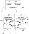
- FIG. 1 a block diagram of a power compensated DSC is shown in FIG. 1 .
- the device 100 includes a sample holder 110 and a reference holder 120. Each of the sample holder 110 and the reference holder 120 includes each own heating element (not shown).
- an exothermic (heat yielded) or endothermic (heat absorbed) change occurs in the sample, power or energy is applied to or removed from one or both of the sample and the reference to compensate for the energy change occurring in the sample.
- a controller 130 is used to determine whether power should be supplied or removed and to which component such power should be supplied or removed. In effect, this power compensation maintains a "thermal null" state at all times. The amount of power required to maintain the system in equilibrium conditions is directly proportional to the energy changes occurring in the sample.
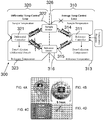
- a typically control system 200 for a DSC is shown in FIG. 2
- the control system includes two separate control loops: a first control loop 210 configured to control the average temperature of the standard and reference holders, and a second control loop 220 configured to control the temperature difference between the sample and reference holders.
- the average control loop 210 compares the arithmetic average of sample and reference temperatures with a temperature program 205. Average power is defined by difference between reference sensor and programmed temperature.
- the average control loop 210 includes a controller 212 which is electrically coupled to the sample sensor 211 and the reference sensor 221 through interconnects or electrical connections 214 and 216, respectively.
- the controller 212 is also electrically coupled to the reference sensor 221 through electrical connections 213 and 215.
- the controller 212 may be configured to provide power, or send a signal to another device to provide power, to the heaters of both the sample 211 and reference 221 sensors through electrical connections shown as 216 and 215, respectively. While shown as having separate connections in FIG. 2 for providing power and sensing the temperature, the controller may have a single electrical connection to the sample holder 211 and a single electrical connection to the reference holder 221. If there is a deviation in temperature between the sample 211 and reference 221 holders, then the average control loop is configured to provide the same electrical output to both the sample holder 211 and the reference holder 221. Due to the feedback, the difference between measured average temperature and programmed temperature is minimized.
- the temperature desired in the temperature program is greater than the average temperature of the sample holder 211 and the reference holder 221, more power will be provided to each of the heaters, which, like the thermometers, are embedded in the sample holder 211 and reference holder 221 to provide a short response time for the system.
- the differential temperature control loop 220 of the DSC shown in FIG. 2 is configured to measure the temperature difference between both the sample holder 211 and the reference holder 221.
- the differential temperature control loop 220 includes a controller 222 electrically coupled to the sample holder 211 and the reference holder 221 through interconnects 224 and 223, respectively.
- the controller 222 may also be coupled to the sample holder 211 and the reference holder 221 through connection 226 and 225, respectively, to adjust the differential power increments provided to the sample holder 211 and the reference holder 221.
- signals representing the sample and reference temperatures measured, for example, by platinum thermometers of the holders, are provided to the differential temperature amplifier.
- the differential temperature amplifier output will then adjust the differential power increment provided to the reference and sample heaters in the direction and magnitude necessary to correct any temperature difference between them.
- additional power may be provided to the sample holder.
- the same amount of power may be subtracted on the reference side. This power is recorded and together with the average temperature profile it provides the complete information about the heat flow to the sample.
- This scheme is implemented, for example, in PerkinElmer DSC calorimeters working up to 8 K/s scanning rate with milligram samples. This control allows for a relatively simple determination of the differential heat flow from the remaining temperature differences between sample and reference cups.
- control loop and more particularly, the average controller 212 shown in FIG. 2 may not respond precisely enough at high heating rates such as, for example, those exceeding 10 K/second to provide adequate measurements.
- the average signal if generated using the control system of FIG. 2 , may contain small and fast events from the nanogram quantities of sample which will not be detected using the conventional control system shown in FIG. 2 .
- a control system as shown in FIG. 3 may be used. Similar to the control system of FIG. 2 , the control system 300 comprises two control loops 310 and 320 but the configuration and/or function of each of the control loop differs from those shown in FIG 2 .
- control reference temperature may be measured without measuring an average temperature of the sample holder.
- the sample temperature lead 312 of the first control loop 310 may be omitted, as shown schematically using an "X" in FIG. 3 , and reference controller 311 does not measure the average temperature of the sample holder 316.
- the controller 311 may be electrically coupled only to the reference holder 316 through lead 313 without any direct electrical connection for monitoring the temperature of the sample holder 326. This configuration permits the use of a relatively slow but precise PID controller for the reference temperature control.
- time resolution for the control of the reference temperature may be orders of magnitude slower compared to the differential controller 321.
- output power range (dynamics) of the reference controller 311 is orders of magnitude larger than for the differential controller 321.
- the differential temperature control loop 320 may have a time constant of about 3 ms, whereas the average temperature control loop 310 has a time constant of about 20 ms.
- the integral part of the reference controller 311 assures that the difference between program temperature and reference temperature is practically zero.
- the same temperature profile in the sample sensor as in the reference sensor may unexpectedly be achieved by applying substantially the same output voltage of the reference controller 311 to the heaters of the sample sensor 326 and the reference sensor 316 through, for example, connections 314 and 315.
- the controller 321 is electrically coupled to the sample sensor 326 and the reference sensor 316, through connections 322 and 323, respectively, and is configured to detect any differences between reference and sample sensor temperatures.
- the controller 321 can then add or subtract its output voltage solely on (or from) the sample sensor 326. That is, the differential power to the reference holder 316 is not monitored, detected, used or altered using controller 321, as shown in the "X" for the differential power connection to the reference holder 316.
- controller 321 as shown in the "X" for the differential power connection to the reference holder 316.
- this configuration permits the use of a precise (but slow) PID controller for control of the reference temperature and a highly sensitive and fast proportional controller for the differential controller.
- control system shown in FIG. 3 may be used to monitor chemical and physical processes of samples using a heating rate (or cooling rate) of 10 K/second or more, for example about 10-1000 K/second, e.g., 10-500 K/second, 10-100 K/second or any value within these illustrative ranges.
- a heating rate or cooling rate
- the calorimeters described herein permit the study of chemical and physical transitions that occur on time scales too rapid for study using conventional calorimeters.
- the heating may be linear such that a linear increase between a starting temperature and a final temperature is implemented with the heating rate being the slope of temperature as a function of time.
- a cooling rate which may be the same or similar to the heating rate, may be used to study processes during cooling of the sample and reference holders.
- the heating and/or cooling may be stepped, non-linear or may take other forms depending in the material being studied and the desired information therefrom.
- control system described herein may be used with conventional calorimetric crucibles or with thin film sample holders, depending on the desired heating rates (or cooling rates).
- high heating rates may be limited by the mass of the measuring cell.
- thin films such as those described by Hager, Allen and co-workers and Lopeandia et al., along with the control systems disclosed herein, small amounts of sample may be studied using high heating and cooling rates.
- the gap in scanning rate between DSC and fast scanning calorimetric techniques ranging between 8...10 ⁇ 2> K/s, an area of interest due to many material processing steps being within this cooling rate range, may be bridged.
- Illustrative thin film sensors include, but are not limited to, those including XI-296, XI-270, XI-272 and XI-292 commercially available from Xensor Integration, The Netherlands and other sensors including, for example, those described in the van Herwaarden, A.W. article listed herein.
- the sizes and dimension of the films may be selected such that they have a low heat capacity as compared to traditional crucibles or cups used in calorimetry.
- the devices disclosed herein may include two high sensitive, low addenda heat capacity thin film sensors, e.g., a XI-296 sensor such as those used for single-sensor fast scanning calorimeters.
- the measuring cell may include a silicon frame having dimensions of about 2.5x5 mm 2 fixed on a standard integrated circuit housing, e.g. a TO-5 housing.
- Calorimeters including the thin films may also include a heater and a thermopile embedded at the center of a freestanding SiN membrane (e.g., 0.5 ⁇ m thick) as shown, for example, in FIGS. 4A-4D.
- FIG. 4A shows the chip (dark) mounted on a TO-5 housing.
- FIG. 4B the thick chip with a silicon frame (dark) and the free standing SiN membrane (light area in the center of the chip) is shown.
- FIG. 4C A more detailed view on the chip is presented in FIG. 4C where the wiring to the measurement area in the center is seen.
- the arrangement of the heater (thick stripes) and the thermopiles (thin stripes) in the center of the membrane is shown on FIG. 4D .
- the size of the heated area may vary from about 8 microns to about 100 microns, for example, about 8 microns by 10 microns or about 60 microns by 80 microns.
- a desired number of thermopiles may be placed in the heated area to allow fast and precise temperature measurement.
- the thermopiles may be produced using suitable lithographic techniques and p- and n-doped silicon, and the hot junctions are placed just in between the two heater stripes while the cold junctions are placed on top of the silicon frame ( FIG. 4C , left and right of the free standing membrane).
- the thermopiles typically include a series of thermocouples that can measure temperature of and/or provide/take away heat to or near the thin films.
- thermopiles include, but are not limited to, semiconducting thermopiles, and thermopiles including one or more of known types of thermocouples.
- illustrative thermocouple types include, but are not limited to, Type B (Platinum/30% Rhodium (+) versus Platiumt/6% Rhodium (-)), Type E (Nickel/10% Chromium (+) versus constantan (-)), Type J (Iron (+) versus constantan (-)), Type K (Nickel/10% Chromium (+) versus Nickel/5% Aluminum-Silicon (-)), Type R (Platinum/13% Rhodium (+) versus Platinum (-), and Type S (Platinum/10% Rhodium (+) versus Platinum (-)), as described, for example, in ANSI C96.1-1964.
- thermocouples such as, for example, pure platinum, platinum palladium, platinum iridium, platinum tungsten and tungsten rhenium thermocouples, however, will be selected by the person of ordinary skill in the art, given the benefit of this disclosure. As detailed herein, many different types of suitable thin films sensors are commercially available from numerous suppliers.
- the thin film may be configured with five or six semiconducting thermopiles placed inside the heating area with the "hot” junction in the center, and the "cold” junction on the frame of the sensor (see FIGS. 4C and 4D ).
- the sample may be placed on the top of the thin film area that is heated so that reliable information about sample temperature for thin samples can be obtained. Otherwise the strong temperature gradients outside the heated area may adversely affect the measurements.
- one or more suitable algorithms may be used to determine the amount of heat produced or lost.
- separation of the control loops in the devices disclosed herein makes the calculation of sample heat capacity more difficult in comparison to the symmetric power compensation scheme such as those commonly used in power compensation DSC, but allows going to higher heating rates with reliable average temperature control.
- the thermal contact between the heater and a thin sample is sufficiently good because of adhesive forces and any residual heat loss may be neglected.
- the heat capacities and thermal resistances of the thin film-heater and of the thermopile are also negligibly small.
- the main heat capacity of the cell is the effective heat capacity of the heated part of the membrane, which is about 2 ⁇ 10 -7 J/K at room temperature.
- the system can be described by the following parameters: the effective heat capacity of the central part of the cell C 0 , the heat capacity of the sample C , and the coefficient of heat exchange, ⁇ , between the central part of the cell and the environment.
- the resistive film-heater about. 1 kOhm resistance, provides the heat flow P 0 ( t ), which is supplied to the thin film/sample interface and propagates through the sample, membrane and the ambient gas.
- T ( t ) and T 0 are the temperatures of the heating region and of the environment, respectively
- P 0 is the power provided to the system
- C and C 0 are the heat capacity of the sample and the thin film sensor, respectively.
- the difference of equation 1 for sample and reference sensors provides the following equation.
- C dT dt P difference .
- P difference is the difference between the power supplied to the sample and the reference sensors.
- P difference can be obtained from the remaining temperature difference between both sensors and the other quantities measured, see, for example, FIG. 7B , using the calorimeters disclosed herein.
- the calorimeters disclosed herein may be conjugated or hyphenated to other analytical devices such that measurements other than heat measurements may also be performed on a sample.
- one or more other analytical devices may be conjugated to the calorimeter for additional analysis of the materials being analyzed or for analysis of gases evolved during the calorimetric analysis.
- Illustrative analytical devices include, but are not limited to, a mass spectrometer (MS), an infrared (IR) spectrometer, a gas chromatograph (GC) and combinations of these techniques.
- Block diagrams illustrating some hyphenated devices are shown in FIGS. 5A-5D .
- Such hyphenated devices may be particular useful for evolved gas analysis, where one or more gases is evolved from the sample during a calorimetric measurement.
- gases may be directed or drawn into another instrument or device using suitable devices such as, for example, vacuum pumps, fans, head space sampling and the like.
- suitable devices such as, for example, vacuum pumps, fans, head space sampling and the like.
- a heated tube may provide fluid coupling between the calorimeter and the MS such that species that evolve as gases in the thermal analysis device may be kept as gases during the transfer to the MS. Additional suitable devices and methods for transferring species from a thermal analysis device to a MS will be readily selected by the person of ordinary skill in the art, given the benefit of this disclosure.
- a system 500 may comprise a calorimeter 510, shown as CAL in the figures, coupled to a mass spectrometer 515.
- the calorimeter 510 may be configured as described herein, for example, with separate control loops.
- the mass spectrometer 515 may be any mass spectrometer commonly used in chemical analysis such as those commercially available, for example, from PerkinElmer Life and Analytical Sciences, Inc. (Waltham, MA).
- Illustrative mass spectrometers include, but are not limited to, those configured to use or implement a magnetic sector mass analyzer, a quadrupole mass analyzer, an ion trap analyzer, a time-of-flight analyzer, those implementing electrospray deionization and other suitable mass analyzers that may separate species with different mass-to-charge ratios. It may be desirable to include one or more valves, fittings or devices to compensate for the difference in pressure between the calorimeter 510 and the mass spectrometer 515. Such pressure compensation will be achieved by the person of ordinary skill in the art, given the benefit of this disclosure.
- a system 520 may comprise a calorimeter 525 coupled to an infrared (IR) spectrometer 530.
- the calorimeter 525 may be configured as described herein, for example, with separate control loops.
- the infrared spectrometer may be any commonly used infrared spectrometers, such as, for example, a continuous wave infrared spectrometer, a single or a dual beam infrared spectrometer, or an interference spectrometer such as a Fourier transform infrared spectrometer. Suitable other infrared spectrometers and suitable methods for coupling a calorimeter to an IR device will be recognized by the person of ordinary skill in the art, given the benefit of this disclosure.
- a system 540 may comprise a calorimeter 545 coupled to a gas chromatography system (GC) 550.
- the calorimeter 545 may be configured as described herein, for example, with separate control loops.
- the GC 550 may receive evolved gas from the calorimeter 545 and separate species within the evolved gas. For example, it may be desirable to separate gaseous reaction products evolved during the calorimetric analysis. It will be within the ability of the person of ordinary skill in the art, given the benefit of this disclosure, to select suitable GC devices for use with the calorimeters disclosed herein.
- a system 560 may comprise a calorimeter 565 coupled to a gas chromatograph 570 which itself is coupled to a mass spectrometer 575.
- the calorimeter 565 may be configured as described herein, for example, with separate control loops.
- the GC 570 and the MS 575 may each be, for example, any of the illustrative GC and MS devices discussed in reference to FIGS. 5A and 5C or other suitable GC and MS devices.
- the illustrative systems shown in FIGS. 5A-5D may also include additional components such as, for example, autosamplers, filters, analysis systems and software, computer interfaces and the like.
- the instrument configurations described herein may be controlled or used with, at least in part, a computer system.
- the computer systems may be, for example, general-purpose computers such as those based on Unix, Intel PENTIUM-type processor, Motorola PowerPC, Sun UltraSPARC, Hewlett-Packard PA-RISC processors, or any other type of processor. It should be appreciated that one or more of any type computer system may be used according to various embodiments of the technology. Further, the system may be located on a single computer or may be distributed among a plurality of computers attached by a communications network.
- a general-purpose computer system according to one embodiment may be configured to perform any of the described functions including but not limited to: data acquisition, calorimeter control, data analysis and the like. It should be appreciated that the system may perform other functions, including network communication, and the technology is not limited to having any particular function or set of functions.
- the computer system may include a processor connected to one or more memory devices, such as a disk drive, memory, or other device for storing data.
- the memory is typically used for storing programs and data during operation of the computer system.
- Components of the computer system may be coupled by an interconnection mechanism, which may include one or more busses (e.g., between components that are integrated within a same machine) and/or a network (e.g., between components that reside on separate discrete machines).
- the interconnection mechanism enables communications (e.g., data, instructions) to be exchanged between system components.
- the computer system typically is electrically coupled to an interface on the system such that electrical signals may be provided from the system to the computer system for storage and/or processing.
- the computer system may also include one or more input devices, for example, a keyboard, mouse, trackball, microphone, touch screen, analog to digital converter (ADC, DAQ boards), and one or more output devices, for example, a printing device, status or other LEDs, display screen, speaker, digital to analog converter (DAC boards) and the like.
- the computer system may contain one or more interfaces that connect the computer system to a communication network (in addition or as an alternative to the interconnection mechanism).
- the storage system of the computer typically includes a computer readable and writeable nonvolatile recording medium in which signals are stored that define a program to be executed by the processor or information stored on or in the medium to be processed by the program. For example, the heating profiles, heating rates, cooling rates and the like may be stored on the medium.
- the medium may, for example, be a disk or flash memory.
- the processor causes data to be read from the nonvolatile recording medium into another memory that allows for faster access to the information by the processor than does the medium.
- This memory is typically a volatile, random access memory such as a dynamic random access memory (DRAM) or static memory (SRAM). It may be located in storage system or in memory system.
- DRAM dynamic random access memory
- SRAM static memory
- the processor generally manipulates the data within the integrated circuit memory and then copies the data to the medium after processing is completed.
- a variety of mechanisms are known for managing data movement between the medium and the integrated circuit memory element, and the technology is not limited thereto. The technology is not limited to a particular memory system or storage system.
- the computer system may also include specially-programmed, special-purpose hardware, for example, an application-specific integrated circuit (ASIC).
- ASIC application-specific integrated circuit
- the computer system may be a general-purpose computer system that is programmable using a high-level computer programming language.
- the computer system may be also implemented using specially programmed, special purpose hardware.
- the processor is typically a commercially available processor such as the well-known Pentium class processor available from the Intel Corporation. Many other processors are available.
- Such a processor usually executes an operating system which may be, for example, the Windows 95, Windows 98, Windows NT, Windows 2000 (Windows ME), Windows XP or Windows Vista operating systems available from the Microsoft Corporation, MAC OS System X operating system available from Apple Computer, the Solaris operating system available from Sun Microsystems, or UNIX or Linux operating systems available from various sources. Many other operating systems may be used.
- the computer system may include a controller such as for example and 8-bit or 16-bit controller. Other controllers such as 32-bit or higher controller may also be used in place of a processor or in addition to the processor of the computer system.
- the processor and operating system together define a computer platform for which application programs in high-level programming languages can be written. It should be understood that the technology is not limited to a particular computer system platform, processor, operating system, or network. Also, it should be apparent to those skilled in the art that the present technology is not limited to a specific programming language or computer system. Further, it should be appreciated that other appropriate programming languages and other appropriate computer systems could also be used.
- the hardware or software is configured to implement cognitive architecture, neural networks or other suitable implementations.
- One or more portions of the computer system may be distributed across one or more computer systems coupled to a communications network. These computer systems also may be general-purpose computer systems. For example, various aspects may be distributed among one or more computer systems configured to provide a service (e.g., servers) to one or more client computers, or to perform an overall task as part of a distributed system. Various aspects may be performed on a client-server or multi-tier system that includes components distributed among one or more server systems that perform various functions according to various embodiments.
- a service e.g., servers
- These components may be executable, intermediate (e.g., IL) or interpreted (e.g., Java) code which communicate over a communication network (e.g., the Internet) using a communication protocol (e.g., TCP/IP).
- a communication network e.g., the Internet
- a communication protocol e.g., TCP/IP
- Various embodiments may be programmed using an object-oriented programming language, such as SmallTalk, Basic, Java, C++, Ada, LabView (National Instruments) or C# (C-Sharp). Other object-oriented programming languages may also be used. Alternatively, functional, scripting, and/or logical programming languages may be used.
- Various aspects may be implemented in a non-programmed environment (e.g., documents created in HTML, XML or other format that, when viewed in a window of a browser program, render aspects of a graphical-user interface (GUI) or perform other functions).
- GUI graphical-user interface
- the desired heating rates, cooling rates, sampling rates and the like may be selected from one or more pull down menus of the graphical user interface.
- a user interface may be provided such that a user may enter desired parameters such as, for example, the heating rates, the cooling rates, sample size, initial power and the like.
- desired parameters such as, for example, the heating rates, the cooling rates, sample size, initial power and the like.
- a control system configured to control the temperature of a sample sensor and a reference sensor of a calorimeter.
- the system is shown in a block diagram in FIG 6 .
- the control system 600 comprises a first controller 610 and a second controller 620 each electrically coupled to a sample sensor 630 and a reference sensor 640 through at least one electrical connection.
- the first controller 610 may be configured to receive a temperature signal from the reference sensor 640 through connection 612.
- the first controller 610 may generate a first control signal based on the temperature signal from the reference sensor 640, e.g., based solely on the temperature signal from the reference sensor 640, and provide power to both the sample sensor 630 and the reference sensor 640 through connections 616 and 614, respectively, based on the generated first control signal.
- the second controller 620 may be configured to receive a temperature signal, from the sample sensor 630 and the reference sensor 640 through connections 626 and 628, respectively.
- the second controller 620 may generate a second control signal to provide differential power only to the sample sensor 630, based on the generated second control signal, through electrical connection 624.
- the sample sensor and the reference sensor may each be thin film sensors that can respond rapidly to alter their temperature during high heating rates.
- the sample sensor and the reference sensor each typically include a sample holder, a heating element (for example, a resistive heating element), and a temperature sensing element (for example, a thermocouple, thermometer or the like).
- the signals provided to the sample sensor 630, and the reference sensor 640 are suitable signals to increase (or decrease) the heat provided by the heating element of that particular sensor so the sample sensor 620 and the reference sensor 640 may remain at substantially the same temperature during the analysis.
- the first controller 610 may be a PID controller
- the second controller 620 may be a proportional controller or other suitable controller that can detect rapid heat changes that may occur due to high heating rates.
- the systems disclosed herein may include additional components such as, for example, an autoloader.
- the autoloader may be configured to load samples (or sensors that include a sample) sequentially into and out of the system such that the system may perform measurements without user intervention or monitoring.
- the autoloader may comprise, for example, a robotic arm and/or motor that can securely grip the samples/sensors and load them into a desired position in the system.
- the system may include other electrical components such as operational amplifiers, gain control devices and the like.
- the system may include a bar code reader so that each sample may be encoded with a bar code and the measurements of each sample can be associated with its respective bar code.
- the autoloader may be configured to load only sample, whereas in other examples, the autoloader may load sensor plus sample into the sampling space.
- a method of measuring physical or chemical changes using a calorimeter comprises controlling a sample sensor and a reference sensor by generating a first control signal using a first controller, the first control signal based on receipt of a temperature signal from only the reference sensor of the calorimeter by the first controller.
- the method may also comprise providing power to the reference sensor and the sample sensor, based the generated first control signal, to control the average temperature of the reference sensor and the sample sensor, e.g., without sensing the temperature of the sample sensor.
- the method may also comprise generating a second control signal using a second controller, the second control signal based of receipt of a temperature signal from each of the reference sensor and the sample sensor to provide a differential temperature between the reference sensor and the sample sensor.
- the method may further comprise providing power to only the sample sensor, based on the generated second control signal, to heat or cool the temperature of the sample sensor to substantially the same temperature as the reference sensor.
- the method may include configuring the first controller to be a proportional-integral-derivative controller.
- the method may include configuring the second controller to be an analog proportional controller.
- the method may include heating the sample sensor and the reference sensor at a heating rate of 10 Kelvin/second or more, e.g., 20, 30, 40, 50, 60, 70, 80, 90, or 100 Kelvin/second or more.
- a method of facilitating calorimeter control is provided. Such method may be performed by providing the controller (or control loop) configurations described herein in the form of a control module, for example.
- the method comprises providing a control module comprising a first controller configured to receive a temperature signal from only a reference sensor and to generate a first control signal, based on the received temperature signal, to provide average power to a sample sensor and to the reference sensor and a second controller configured to receive temperature signals from both the sample sensor and the reference sensor and to generate a second control signal, based on the temperature signals received from both the sample sensor and the reference sensor, to provide differential power to only the sample sensor.
- the module can interface with existing calorimetric devices or may itself include spaces for a sample sensor and a reference sensor that can be coupled to the controller of the module as described herein.
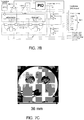
- a calorimeter having a control system with two control loops was constructed as follows: two calorimetric sensors, one with sample the other without sample, were placed in a thermostat, as shown in the photograph of FIG. 7C , at a controlled temperature, e.g. 35 °C as indicated in FIG. 7B , and with a selected ambient gas, e.g. helium or nitrogen at 50 kPa or 100 kPa.
- the sensor was in good thermal contact to the thermostat and the cold junction temperature of the thermopile equaled the thermostat temperature.
- the sensors were connected to the two control loops as schematically shown in FIG. 7A and in detail in FIG. 7B .
- Amplifier X1 (SIM910, low output noise, 1 MHz bandwidth voltage amplifier) amplified the thermopile output from the reference sensor 710 and provided it to the PID controller 730 (SIM960, analog PID) which serves as the reference controller for the average temperature control loop 310, as described in reference to FIG. 3 .
- the PID compares the measured reference sensors' temperature with the predefined temperature program 750.
- the output of the PID was provided to the heater of the reference sensor 710, which was in series with some wire resistors indicated by boxes in FIG. 7B and a constant resistor of 1.5 KOhm allowed measurement of the current through the heater. All voltages needed to recalculate power and finally differential power as needed in Eq.
- analog devices were used to shorten response time and therefore allow high rate temperature processing.
- an analog PID controller was used to control reference sensor temperature and to provide average power to both sensors.
- the programmed temperature as function of time was supplied to the PID from a computer or controller according to a user-defined temperature profile.
- the difference was amplified and added to the voltage that was provided to the sample side heater.
- the differential control loop consisted of a high frequency analog amplifier so that it had a very fast response time on the order of one or a few microseconds.
- Differential power and all voltages needed for measurements were collected by the computer using, for example, an ADC/DAC board.
- the used SRS Small Instrumentation Module analog device frame permitted controlling parameters of the analyses from a computer.
- the program for managing the experiment and obtaining data was developed using LabViewTM.
- FIGS. 8A and 8B show the results of heating single spherical tin particles (about 350 nanograms) with a heating-cooling rate of 500 K/s measured with the device of Example 1 , with the reference sensor being an empty sensor in all the measurements described below.
- FIG. 8A shows the temperature program and remaining temperature difference between sample and reference sensors.
- FIG. 8B shows the heat capacity from the data shown in FIG. 8A .
- the peak shape is determined by the heat transfer from the sensor to the relatively heavy sample.
- the well known linear leading edge of the peak is shown in FIG. 8A . From the width of the peak the time for melting (the heat transfer) was estimated as 29 milliseconds. Crystallization on cooling was much faster because of about 100 K supercooling. The crystallization can be considered nearly as a delta function.
- the response time of the instrument was estimated to be 3 milliseconds. The crystallization peak nicely demonstrated the power of the device in handling fast processes.
- FIG. 9A the results of heating single spherical tin particles (about 35 nanograms) using a single sensor device, as described in the Minakov (Rev. Sci. Instr. 2007 ) article listed below, and the device of Example 1 are shown.
- the melting curves for the small tin sample were compared for the single sensor chip calorimeter without active control and the power-compensated differential chip calorimeter at different heating rates. While the single sensor device yielded very round curves, the differential device of Example 1 provided the expected triangle like melting curves as known from power compensation DSCs. The differential setup provided more realistic data with less distortion by the instrument.
- FIG. 9B shows placement of the sample on the sensor.
- the effect of differential gain settings using the device of Example 1 was determined using about 350 micrograms of a tin sample, with the settings for the reference controller remaining constant.
- the single spherical particles were melted using a heating rate of 1,000 K/s and the different, differential gain settings.
- FIG. 10A shows the remaining temperature difference at different gains.
- FIG. 10B shows the power difference, calculated from the data shown in FIG. 10A .
- the inset of FIG. 10B shows the peak area as a function of gain setting. At low gain settings, the melting peak was much broader than for higher gain settings. Not enough heat was provided to the sample sensor, and consequently to the sample, allowing the sample to melt as fast as limited by the heat transfer (thermal resistor) between the sensor and the sample.
- Polymers are known to show strong kinetic effects on crystallization and melting at high rates.
- An example of a polymer melting curve is shown in FIG. 11A .
- the inset of FIG. 11A shows the temperature profile. At rates below 200 K/second, crystallization was observed at cooling. The crystallization peak shifted to lower temperatures at increasing cooling rates and disappeared for rates above 200 K/s. On heating, cold crystallization was observed even at heating rates of 10,000 K/s. The glass transition at about 270 K as well as the cold crystallization shifted to higher temperatures with increasing heating rates.
- isothermal crystallization experiments for isotactic polypropylene may be performed at any temperature.
- An example of this type of measurement is shown in FIG. 12 .
- the temperature difference between the sample and reference sensors equilibrated within about five milliseconds.
- the exothermic crystallization process manifested itself as an increase in temperature of the sample sensor as shown in the inset of FIG. 12 . Even though there was a temperature increase, the measurement can be considered as isothermal because the increase is only about 0.5 K or less.
Landscapes
- Chemical & Material Sciences (AREA)
- Engineering & Computer Science (AREA)
- Combustion & Propulsion (AREA)
- Physics & Mathematics (AREA)
- General Physics & Mathematics (AREA)
- Chemical Kinetics & Catalysis (AREA)
- Health & Medical Sciences (AREA)
- Life Sciences & Earth Sciences (AREA)
- Analytical Chemistry (AREA)
- Biochemistry (AREA)
- General Health & Medical Sciences (AREA)
- Immunology (AREA)
- Pathology (AREA)
- Investigating Or Analyzing Materials Using Thermal Means (AREA)
Claims (13)
- Système de commande pour un calorimètre comprenant un capteur d'échantillon (326, 630) et un capteur de référence (316, 640), ce système de commande comprenant :un premier régulateur (311, 610) configuré de façon à recevoir un signal de température seulement du capteur de référence et à générer un premier signal de commande, en se basant sur le signal de température reçu, afin de fournir du courant au capteur d'échantillon et au capteur de référence ; etun deuxième régulateur (321, 620) configuré de façon à recevoir des signaux de température à la fois du capteur d'échantillon et du capteur de référence et à générer un deuxième signal de commande afin de fournir un courant différentiel seulement au capteur d'échantillon ;un support de stockage configuré avec un programme de température avec une vitesse de chauffage ou de refroidissement sélectionnée d'au moins 10 kelvins/seconde,au moins soit le premier, soit le deuxième régulateur étant un régulateur proportionnel configuré de façon à détecter des changements de température à une vitesse d'échauffement de 10 kelvins/seconde ou plus.
- Système de commande selon la revendication 1, dans lequel le premier régulateur est un régulateur proportionnel intégral dérivé et le deuxième régulateur est un régulateur proportionnel analogique.
- Système de commande selon la revendication 2, dans lequel le premier régulateur et le deuxième régulateur sont configurés de façon à fournir du courant à un capteur d'échantillon à film mince et à un capteur de référence à film mince.
- Système de commande selon la revendication 1, dans lequel le deuxième régulateur est configuré de façon à détecter des changements de température à une vitesse d'échauffement de 10 kelvins/seconde ou plus.
- Système de commande selon la revendication 1, dans lequel le deuxième régulateur est un régulateur proportionnel intégral dérivé.
- Calorimètre comprenant un système de commande selon la revendication 1, dans lequel le capteur d'échantillon est un capteur d'échantillon à film mince et le capteur de référence est un capteur de référence à film mince.
- Calorimètre selon la revendication 6, dans lequel le premier régulateur est un régulateur proportionnel intégral dérivé.
- Calorimètre selon la revendication 7, dans lequel le deuxième régulateur est un régulateur proportionnel analogique.
- Calorimètre selon la revendication 6, dans lequel une vitesse de refroidissement du programme de température est au moins 10 kelvins/seconde.
- Calorimètre selon la revendication 6, dans lequel chacun du capteur d'échantillon à film mince et du capteur de référence à film mince est un capteur XI-296, un capteur XI-270, un capteur XI-272 ou un capteur XI-292.
- Procédé pour faciliter la commande d'un calorimètre, ce procédé comprenant :
la fourniture d'un module de commande comprenant :un premier régulateur configuré de façon à recevoir un signal de température seulement d'un capteur de référence et à générer un premier signal de commande, en se basant sur le signal de température reçu, afin de fournir un courant moyen à un capteur d'échantillon et au capteur de référence ; etun deuxième régulateur configuré de façon à recevoir des signaux de température à la fois du capteur d'échantillon et du capteur de référence et à générer un deuxième signal de commande, en se basant sur les signaux de température reçus à la fois du capteur d'échantillon et du capteur de référence, afin de fournir un courant différentiel seulement au capteur d'échantillon ; etun support de stockage configuré avec un programme de température avec une vitesse d'échauffement ou de refroidissement sélectionnée d'au moins 10 kelvins/seconde,au moins un des régulateurs étant un régulateur proportionnel qui détecte des changements de température à une vitesse d'échauffement de 10 kelvins/seconde ou plus. - Procédé de commande d'un calorimètre qui comprend un capteur de référence et un capteur d'échantillon, ce procédé comprenant le procédé selon la revendication 11 et comprenant en outre :la génération d'un premier signal de commande en utilisant le premier régulateur ;la fourniture d'un courant au capteur de référence et au capteur d'échantillon, en se basant sur le premier signal de commande généré, afin de réguler la température moyenne du capteur de référence et du capteur d'échantillon ;la génération d'un deuxième signal de commande en utilisant le deuxième régulateur ;le stockage d'un programme de température avec une vitesse d'échauffement ou de refroidissement sélectionnée d'au moins 10 kelvins/seconde ; etla fourniture d'un courant différentiel seulement au capteur d'échantillon, en se basant sur le deuxième signal de commande généré, pour élever ou abaisser la température du capteur d'échantillon à essentiellement la même température que le capteur de référence.
- Procédé selon la revendication 12, comprenant en outre le chauffage du capteur d'échantillon et du capteur de référence à une vitesse d'échauffement de 10 kelvins/seconde ou plus.
Applications Claiming Priority (2)
| Application Number | Priority Date | Filing Date | Title |
|---|---|---|---|
| US5932108P | 2008-06-06 | 2008-06-06 | |
| PCT/US2009/046385 WO2009149333A1 (fr) | 2008-06-06 | 2009-06-05 | Calorimètre et procédés d'utilisation et systèmes de commande y afférant |
Publications (3)
| Publication Number | Publication Date |
|---|---|
| EP2283346A1 EP2283346A1 (fr) | 2011-02-16 |
| EP2283346A4 EP2283346A4 (fr) | 2014-11-05 |
| EP2283346B1 true EP2283346B1 (fr) | 2018-11-21 |
Family
ID=41398545
Family Applications (1)
| Application Number | Title | Priority Date | Filing Date |
|---|---|---|---|
| EP09759491.5A Not-in-force EP2283346B1 (fr) | 2008-06-06 | 2009-06-05 | Calorimètre et procédés d'utilisation et systèmes de commande y afférant |
Country Status (7)
| Country | Link |
|---|---|
| US (1) | US8231267B2 (fr) |
| EP (1) | EP2283346B1 (fr) |
| JP (1) | JP5461536B2 (fr) |
| CN (1) | CN202267663U (fr) |
| AU (1) | AU2009256035B2 (fr) |
| CA (1) | CA2725861C (fr) |
| WO (1) | WO2009149333A1 (fr) |
Families Citing this family (21)
| Publication number | Priority date | Publication date | Assignee | Title |
|---|---|---|---|---|
| GB0605683D0 (en) * | 2006-03-21 | 2006-05-03 | Servomex Group Ltd | Thermal conductivity sensor |
| US8388220B2 (en) | 2007-05-16 | 2013-03-05 | Waters Technologies Corporation | Large array differential scanning calorimeter, DSC measuring unit |
| EP2214005B1 (fr) * | 2009-02-03 | 2019-09-18 | Mettler-Toledo GmbH | Instrument thermo-analytique |
| US9476780B2 (en) | 2011-03-11 | 2016-10-25 | Alliance For Sustainable Energy, Llc | Calorimeters for testing energy storage systems and power electronics methods of making the same and methods of use |
| CN102534567B (zh) * | 2012-03-21 | 2014-01-15 | 中微半导体设备(上海)有限公司 | 控制化学气相沉积腔室内的基底加热的装置及方法 |
| US20140012534A1 (en) * | 2012-07-04 | 2014-01-09 | Christopher D. Prest | Non-destructive method to determine crystallinity in amorphous alloy using specific heat capacity |
| RU2521208C1 (ru) * | 2013-02-13 | 2014-06-27 | Федеральное государственное бюджетное образовательное учреждение высшего профессионального образования "Сибирская государственная геодезическая академия" (ФГБОУ ВПО "СГГА") | Дифференциальный массивный тонкопленочный калориметр |
| WO2014130689A1 (fr) * | 2013-02-22 | 2014-08-28 | Bird Technologies Group Inc. | Calorimètre de microfabrication pour mesurer une puissance rf |
| RU2671985C2 (ru) * | 2013-05-17 | 2018-11-08 | Шлюмбергер Текнолоджи Б.В. | Способ и устройство для определения характеристик потока текучей среды |
| CN103743775B (zh) | 2013-10-22 | 2016-04-20 | 南京大学 | 一种可与其它显微结构表征技术联用的冷热台型高速量热仪 |
| FR3015682B1 (fr) * | 2013-12-24 | 2021-01-15 | Inst De Rech Tech Jules Verne | Procede pour la determination de la cinetique de cristallisation d’un polymere par analyse calorimetrique differentielle d’un nano-echantillon |
| US9702837B2 (en) * | 2014-12-02 | 2017-07-11 | Kuwait Institute For Scientific Research | System for measuring glass transition temperature of a polymer |
| CN104898734B (zh) * | 2015-05-18 | 2017-12-29 | 中国地质大学(武汉) | 一种动态式温差控制记录装置 |
| WO2019079878A1 (fr) * | 2017-10-27 | 2019-05-02 | Rostrum Medical Innovations Inc. | Capteur de qualité d'air et de composition d'air |
| JP7141608B2 (ja) * | 2018-12-13 | 2022-09-26 | 株式会社東レリサーチセンター | 高速カロリメトリーを用いた熱硬化性樹脂のガラス転移温度の測定方法 |
| JP6792040B1 (ja) * | 2019-09-25 | 2020-11-25 | ネッチ ゲレーテバウ ゲーエムベーハー | 熱分析装置、試料ホルダ組立体及び熱分析方法 |
| CN110823943A (zh) * | 2019-11-20 | 2020-02-21 | 南京大学射阳高新技术研究院 | 一种模块化结构超快扫描量热仪 |
| WO2021097932A1 (fr) * | 2019-11-20 | 2021-05-27 | 南京大学射阳高新技术研究院 | Calorimètre à balayage rapide à capteur unique basé sur un chauffage par laser |
| AT524363B1 (de) * | 2020-10-30 | 2022-06-15 | Anton Paar Gmbh | Messgerät mit elektrothermischem Wandler zum Einstellen eines thermischen Widerstandes, und Betriebsverfahren |
| WO2023023198A1 (fr) * | 2021-08-20 | 2023-02-23 | Texas Tech University System | Calorimètre à vide comprenant un calorimètre différentiel à système ouvert |
| CN114199937B (zh) * | 2021-12-09 | 2023-03-24 | 沈阳化工研究院有限公司 | 一种超低温反应的量热测试方法 |
Family Cites Families (12)
| Publication number | Priority date | Publication date | Assignee | Title |
|---|---|---|---|---|
| US3675465A (en) * | 1969-10-07 | 1972-07-11 | Gunter Sommer | Apparatus and method for differential thermal analysis |
| GB2156974B (en) * | 1984-04-02 | 1988-10-05 | Dow Chemical Co | Combined thermal analyzer and x-ray diffractometer |
| US4821303A (en) * | 1986-12-05 | 1989-04-11 | The Dow Chemical Company | Combined thermal analyzer and x-ray diffractometer |
| WO1994008090A1 (fr) * | 1992-10-02 | 1994-04-14 | Cargill, Incorporated | Papier pourvu d'un couchage en polymere de lactide stable a la fusion et procede de fabrication |
| JP3556227B2 (ja) * | 1994-06-01 | 2004-08-18 | ザ パーキン−エルマー コーポレイション | 実部信号成分と虚部信号成分を用いた示差分析のための装置および方法 |
| US5549387A (en) * | 1994-06-01 | 1996-08-27 | The Perkin-Elmer Corporation | Apparatus and method for differential analysis using real and imaginary signal components |
| US5672289A (en) * | 1996-01-11 | 1997-09-30 | The Perkin-Elmer Corporation | Heater control circuit |
| EP0883801B1 (fr) * | 1996-11-01 | 2004-09-15 | TA Instruments, Inc. | Calorimètre différentiel à balayage |
| JP3434694B2 (ja) * | 1997-12-01 | 2003-08-11 | セイコーインスツルメンツ株式会社 | 示差走査熱量計 |
| JP2001305086A (ja) * | 2000-04-26 | 2001-10-31 | Seiko Instruments Inc | 熱分析装置 |
| JP2006105935A (ja) * | 2004-10-08 | 2006-04-20 | Tokyo Institute Of Technology | 微小熱分析用プローブおよび微小熱分析装置ならびに微小熱分析方法 |
| JP4868305B2 (ja) | 2006-01-27 | 2012-02-01 | エスアイアイ・ナノテクノロジー株式会社 | 示差走査熱量計 |
-
2009
- 2009-06-05 CA CA2725861A patent/CA2725861C/fr active Active
- 2009-06-05 EP EP09759491.5A patent/EP2283346B1/fr not_active Not-in-force
- 2009-06-05 WO PCT/US2009/046385 patent/WO2009149333A1/fr not_active Ceased
- 2009-06-05 US US12/479,105 patent/US8231267B2/en not_active Expired - Fee Related
- 2009-06-05 JP JP2011512679A patent/JP5461536B2/ja not_active Expired - Fee Related
- 2009-06-05 AU AU2009256035A patent/AU2009256035B2/en not_active Ceased
- 2009-06-05 CN CN2009901003014U patent/CN202267663U/zh not_active Expired - Lifetime
Non-Patent Citations (1)
| Title |
|---|
| None * |
Also Published As
| Publication number | Publication date |
|---|---|
| US8231267B2 (en) | 2012-07-31 |
| JP2011523060A (ja) | 2011-08-04 |
| AU2009256035A1 (en) | 2009-12-10 |
| JP5461536B2 (ja) | 2014-04-02 |
| CA2725861A1 (fr) | 2009-12-10 |
| CA2725861C (fr) | 2018-07-10 |
| EP2283346A4 (fr) | 2014-11-05 |
| US20100046573A1 (en) | 2010-02-25 |
| AU2009256035B2 (en) | 2014-05-15 |
| EP2283346A1 (fr) | 2011-02-16 |
| CN202267663U (zh) | 2012-06-06 |
| WO2009149333A1 (fr) | 2009-12-10 |
Similar Documents
| Publication | Publication Date | Title |
|---|---|---|
| US8231267B2 (en) | Calorimeter and methods of using it and control systems therefor | |
| Zhuravlev et al. | Fast scanning power compensated differential scanning nano-calorimeter: 1. The device | |
| Adamovsky et al. | Scanning microcalorimetry at high cooling rate | |
| Minakov et al. | Non-adiabatic thin-film (chip) nanocalorimetry | |
| Van Herwaarden et al. | Design, performance and analysis of thermal lag of the UFS1 twin-calorimeter chip for fast scanning calorimetry using the Mettler-Toledo Flash DSC 1 | |
| CN107014859B (zh) | 热分析仪 | |
| US5288147A (en) | Thermopile differential thermal analysis sensor | |
| JP3594607B2 (ja) | 実部成分と虚部成分を用いた示差分析 | |
| Huth et al. | Differential AC-chip calorimeter for glass transition measurements in ultra thin polymeric films | |
| Minakov et al. | Advanced nonadiabatic ultrafast nanocalorimetry and superheating phenomenon in linear polymers | |
| CN102713586A (zh) | 用于热分析的系统和方法 | |
| Minakov et al. | Isothermal reorganization of poly (ethylene terephthalate) revealed by fast calorimetry (1000 K s− 1; 5 ms) | |
| Schick et al. | Differential scanning calorimetry and differential thermal analysis | |
| Revaz et al. | Si-N membrane-based microcalorimetry: Heat capacity and thermal conductivity of thin films | |
| US7626144B2 (en) | Method and apparatus for rapid temperature changes | |
| Inaba | Nano-watt stabilized DSC and ITS applications | |
| Bierer et al. | MEMS based metal oxide sensor for simultaneous measurement of gas induced changes of the heating power and the sensing resistance | |
| JPH10504381A (ja) | 実部信号成分と虚部信号成分を用いた示差分析のための装置および方法 | |
| Mehta | Characterization techniques for the study of thermally activated phase transitions and determination of thermophysical/kinetic properties | |
| Razouk et al. | A new in situ electrical calibration system for high temperature Calvet calorimeters | |
| Zheng et al. | Temperature-resistance sensor arrays for combinatorial study of phase transitions in shape memory alloys and metallic glasses | |
| JP2006105935A (ja) | 微小熱分析用プローブおよび微小熱分析装置ならびに微小熱分析方法 | |
| Harasztosi et al. | Microcalorimeter development and calibration based on a twin micro-heater platform | |
| Schmon et al. | Thermophysical properties of Manganin (Cu86Mn12Ni2) in the solid and liquid state | |
| Guenther et al. | High-temperature chip calorimeter with atmosphere control |
Legal Events
| Date | Code | Title | Description |
|---|---|---|---|
| PUAI | Public reference made under article 153(3) epc to a published international application that has entered the european phase |
Free format text: ORIGINAL CODE: 0009012 |
|
| 17P | Request for examination filed |
Effective date: 20101206 |
|
| AK | Designated contracting states |
Kind code of ref document: A1 Designated state(s): AT BE BG CH CY CZ DE DK EE ES FI FR GB GR HR HU IE IS IT LI LT LU LV MC MK MT NL NO PL PT RO SE SI SK TR |
|
| AX | Request for extension of the european patent |
Extension state: AL BA RS |
|
| DAX | Request for extension of the european patent (deleted) | ||
| A4 | Supplementary search report drawn up and despatched |
Effective date: 20141002 |
|
| RIC1 | Information provided on ipc code assigned before grant |
Ipc: G01K 17/04 20060101ALI20140926BHEP Ipc: G01N 25/48 20060101AFI20140926BHEP |
|
| GRAP | Despatch of communication of intention to grant a patent |
Free format text: ORIGINAL CODE: EPIDOSNIGR1 |
|
| STAA | Information on the status of an ep patent application or granted ep patent |
Free format text: STATUS: GRANT OF PATENT IS INTENDED |
|
| INTG | Intention to grant announced |
Effective date: 20180518 |
|
| GRAS | Grant fee paid |
Free format text: ORIGINAL CODE: EPIDOSNIGR3 |
|
| GRAJ | Information related to disapproval of communication of intention to grant by the applicant or resumption of examination proceedings by the epo deleted |
Free format text: ORIGINAL CODE: EPIDOSDIGR1 |
|
| GRAL | Information related to payment of fee for publishing/printing deleted |
Free format text: ORIGINAL CODE: EPIDOSDIGR3 |
|
| STAA | Information on the status of an ep patent application or granted ep patent |
Free format text: STATUS: REQUEST FOR EXAMINATION WAS MADE |
|
| GRAR | Information related to intention to grant a patent recorded |
Free format text: ORIGINAL CODE: EPIDOSNIGR71 |
|
| STAA | Information on the status of an ep patent application or granted ep patent |
Free format text: STATUS: GRANT OF PATENT IS INTENDED |
|
| GRAA | (expected) grant |
Free format text: ORIGINAL CODE: 0009210 |
|
| STAA | Information on the status of an ep patent application or granted ep patent |
Free format text: STATUS: THE PATENT HAS BEEN GRANTED |
|
| INTC | Intention to grant announced (deleted) | ||
| AK | Designated contracting states |
Kind code of ref document: B1 Designated state(s): AT BE BG CH CY CZ DE DK EE ES FI FR GB GR HR HU IE IS IT LI LT LU LV MC MK MT NL NO PL PT RO SE SI SK TR |
|
| INTG | Intention to grant announced |
Effective date: 20181016 |
|
| REG | Reference to a national code |
Ref country code: CH Ref legal event code: EP |
|
| REG | Reference to a national code |
Ref country code: IE Ref legal event code: FG4D |
|
| REG | Reference to a national code |
Ref country code: DE Ref legal event code: R096 Ref document number: 602009055792 Country of ref document: DE |
|
| REG | Reference to a national code |
Ref country code: AT Ref legal event code: REF Ref document number: 1068115 Country of ref document: AT Kind code of ref document: T Effective date: 20181215 |
|
| REG | Reference to a national code |
Ref country code: NL Ref legal event code: MP Effective date: 20181121 |
|
| REG | Reference to a national code |
Ref country code: AT Ref legal event code: MK05 Ref document number: 1068115 Country of ref document: AT Kind code of ref document: T Effective date: 20181121 |
|
| PG25 | Lapsed in a contracting state [announced via postgrant information from national office to epo] |
Ref country code: BG Free format text: LAPSE BECAUSE OF FAILURE TO SUBMIT A TRANSLATION OF THE DESCRIPTION OR TO PAY THE FEE WITHIN THE PRESCRIBED TIME-LIMIT Effective date: 20190221 Ref country code: HR Free format text: LAPSE BECAUSE OF FAILURE TO SUBMIT A TRANSLATION OF THE DESCRIPTION OR TO PAY THE FEE WITHIN THE PRESCRIBED TIME-LIMIT Effective date: 20181121 Ref country code: IS Free format text: LAPSE BECAUSE OF FAILURE TO SUBMIT A TRANSLATION OF THE DESCRIPTION OR TO PAY THE FEE WITHIN THE PRESCRIBED TIME-LIMIT Effective date: 20190321 Ref country code: NO Free format text: LAPSE BECAUSE OF FAILURE TO SUBMIT A TRANSLATION OF THE DESCRIPTION OR TO PAY THE FEE WITHIN THE PRESCRIBED TIME-LIMIT Effective date: 20190221 Ref country code: ES Free format text: LAPSE BECAUSE OF FAILURE TO SUBMIT A TRANSLATION OF THE DESCRIPTION OR TO PAY THE FEE WITHIN THE PRESCRIBED TIME-LIMIT Effective date: 20181121 Ref country code: LT Free format text: LAPSE BECAUSE OF FAILURE TO SUBMIT A TRANSLATION OF THE DESCRIPTION OR TO PAY THE FEE WITHIN THE PRESCRIBED TIME-LIMIT Effective date: 20181121 Ref country code: LV Free format text: LAPSE BECAUSE OF FAILURE TO SUBMIT A TRANSLATION OF THE DESCRIPTION OR TO PAY THE FEE WITHIN THE PRESCRIBED TIME-LIMIT Effective date: 20181121 Ref country code: AT Free format text: LAPSE BECAUSE OF FAILURE TO SUBMIT A TRANSLATION OF THE DESCRIPTION OR TO PAY THE FEE WITHIN THE PRESCRIBED TIME-LIMIT Effective date: 20181121 Ref country code: FI Free format text: LAPSE BECAUSE OF FAILURE TO SUBMIT A TRANSLATION OF THE DESCRIPTION OR TO PAY THE FEE WITHIN THE PRESCRIBED TIME-LIMIT Effective date: 20181121 |
|
| PG25 | Lapsed in a contracting state [announced via postgrant information from national office to epo] |
Ref country code: SE Free format text: LAPSE BECAUSE OF FAILURE TO SUBMIT A TRANSLATION OF THE DESCRIPTION OR TO PAY THE FEE WITHIN THE PRESCRIBED TIME-LIMIT Effective date: 20181121 Ref country code: NL Free format text: LAPSE BECAUSE OF FAILURE TO SUBMIT A TRANSLATION OF THE DESCRIPTION OR TO PAY THE FEE WITHIN THE PRESCRIBED TIME-LIMIT Effective date: 20181121 Ref country code: GR Free format text: LAPSE BECAUSE OF FAILURE TO SUBMIT A TRANSLATION OF THE DESCRIPTION OR TO PAY THE FEE WITHIN THE PRESCRIBED TIME-LIMIT Effective date: 20190222 Ref country code: PT Free format text: LAPSE BECAUSE OF FAILURE TO SUBMIT A TRANSLATION OF THE DESCRIPTION OR TO PAY THE FEE WITHIN THE PRESCRIBED TIME-LIMIT Effective date: 20190321 |
|
| PG25 | Lapsed in a contracting state [announced via postgrant information from national office to epo] |
Ref country code: IT Free format text: LAPSE BECAUSE OF FAILURE TO SUBMIT A TRANSLATION OF THE DESCRIPTION OR TO PAY THE FEE WITHIN THE PRESCRIBED TIME-LIMIT Effective date: 20181121 Ref country code: DK Free format text: LAPSE BECAUSE OF FAILURE TO SUBMIT A TRANSLATION OF THE DESCRIPTION OR TO PAY THE FEE WITHIN THE PRESCRIBED TIME-LIMIT Effective date: 20181121 Ref country code: CZ Free format text: LAPSE BECAUSE OF FAILURE TO SUBMIT A TRANSLATION OF THE DESCRIPTION OR TO PAY THE FEE WITHIN THE PRESCRIBED TIME-LIMIT Effective date: 20181121 Ref country code: PL Free format text: LAPSE BECAUSE OF FAILURE TO SUBMIT A TRANSLATION OF THE DESCRIPTION OR TO PAY THE FEE WITHIN THE PRESCRIBED TIME-LIMIT Effective date: 20181121 |
|
| REG | Reference to a national code |
Ref country code: DE Ref legal event code: R097 Ref document number: 602009055792 Country of ref document: DE |
|
| PG25 | Lapsed in a contracting state [announced via postgrant information from national office to epo] |
Ref country code: RO Free format text: LAPSE BECAUSE OF FAILURE TO SUBMIT A TRANSLATION OF THE DESCRIPTION OR TO PAY THE FEE WITHIN THE PRESCRIBED TIME-LIMIT Effective date: 20181121 Ref country code: SK Free format text: LAPSE BECAUSE OF FAILURE TO SUBMIT A TRANSLATION OF THE DESCRIPTION OR TO PAY THE FEE WITHIN THE PRESCRIBED TIME-LIMIT Effective date: 20181121 Ref country code: EE Free format text: LAPSE BECAUSE OF FAILURE TO SUBMIT A TRANSLATION OF THE DESCRIPTION OR TO PAY THE FEE WITHIN THE PRESCRIBED TIME-LIMIT Effective date: 20181121 |
|
| PLBE | No opposition filed within time limit |
Free format text: ORIGINAL CODE: 0009261 |
|
| STAA | Information on the status of an ep patent application or granted ep patent |
Free format text: STATUS: NO OPPOSITION FILED WITHIN TIME LIMIT |
|
| 26N | No opposition filed |
Effective date: 20190822 |
|
| PG25 | Lapsed in a contracting state [announced via postgrant information from national office to epo] |
Ref country code: SI Free format text: LAPSE BECAUSE OF FAILURE TO SUBMIT A TRANSLATION OF THE DESCRIPTION OR TO PAY THE FEE WITHIN THE PRESCRIBED TIME-LIMIT Effective date: 20181121 |
|
| PG25 | Lapsed in a contracting state [announced via postgrant information from national office to epo] |
Ref country code: MC Free format text: LAPSE BECAUSE OF FAILURE TO SUBMIT A TRANSLATION OF THE DESCRIPTION OR TO PAY THE FEE WITHIN THE PRESCRIBED TIME-LIMIT Effective date: 20181121 |
|
| REG | Reference to a national code |
Ref country code: CH Ref legal event code: PL |
|
| REG | Reference to a national code |
Ref country code: BE Ref legal event code: MM Effective date: 20190630 |
|
| PG25 | Lapsed in a contracting state [announced via postgrant information from national office to epo] |
Ref country code: TR Free format text: LAPSE BECAUSE OF FAILURE TO SUBMIT A TRANSLATION OF THE DESCRIPTION OR TO PAY THE FEE WITHIN THE PRESCRIBED TIME-LIMIT Effective date: 20181121 |
|
| PG25 | Lapsed in a contracting state [announced via postgrant information from national office to epo] |
Ref country code: IE Free format text: LAPSE BECAUSE OF NON-PAYMENT OF DUE FEES Effective date: 20190605 |
|
| PG25 | Lapsed in a contracting state [announced via postgrant information from national office to epo] |
Ref country code: BE Free format text: LAPSE BECAUSE OF NON-PAYMENT OF DUE FEES Effective date: 20190630 Ref country code: CH Free format text: LAPSE BECAUSE OF NON-PAYMENT OF DUE FEES Effective date: 20190630 Ref country code: LU Free format text: LAPSE BECAUSE OF NON-PAYMENT OF DUE FEES Effective date: 20190605 Ref country code: LI Free format text: LAPSE BECAUSE OF NON-PAYMENT OF DUE FEES Effective date: 20190630 |
|
| PG25 | Lapsed in a contracting state [announced via postgrant information from national office to epo] |
Ref country code: FR Free format text: LAPSE BECAUSE OF NON-PAYMENT OF DUE FEES Effective date: 20190630 |
|
| REG | Reference to a national code |
Ref country code: DE Ref legal event code: R082 Ref document number: 602009055792 Country of ref document: DE Representative=s name: VENNER SHIPLEY GERMANY LLP, DE Ref country code: DE Ref legal event code: R082 Ref document number: 602009055792 Country of ref document: DE Representative=s name: VENNER SHIPLEY LLP, DE |
|
| PG25 | Lapsed in a contracting state [announced via postgrant information from national office to epo] |
Ref country code: CY Free format text: LAPSE BECAUSE OF FAILURE TO SUBMIT A TRANSLATION OF THE DESCRIPTION OR TO PAY THE FEE WITHIN THE PRESCRIBED TIME-LIMIT Effective date: 20181121 |
|
| PG25 | Lapsed in a contracting state [announced via postgrant information from national office to epo] |
Ref country code: MT Free format text: LAPSE BECAUSE OF FAILURE TO SUBMIT A TRANSLATION OF THE DESCRIPTION OR TO PAY THE FEE WITHIN THE PRESCRIBED TIME-LIMIT Effective date: 20181121 Ref country code: HU Free format text: LAPSE BECAUSE OF FAILURE TO SUBMIT A TRANSLATION OF THE DESCRIPTION OR TO PAY THE FEE WITHIN THE PRESCRIBED TIME-LIMIT; INVALID AB INITIO Effective date: 20090605 |
|
| PG25 | Lapsed in a contracting state [announced via postgrant information from national office to epo] |
Ref country code: MK Free format text: LAPSE BECAUSE OF FAILURE TO SUBMIT A TRANSLATION OF THE DESCRIPTION OR TO PAY THE FEE WITHIN THE PRESCRIBED TIME-LIMIT Effective date: 20181121 |
|
| P01 | Opt-out of the competence of the unified patent court (upc) registered |
Effective date: 20230601 |
|
| PGFP | Annual fee paid to national office [announced via postgrant information from national office to epo] |
Ref country code: DE Payment date: 20230418 Year of fee payment: 15 |
|
| PGFP | Annual fee paid to national office [announced via postgrant information from national office to epo] |
Ref country code: GB Payment date: 20230420 Year of fee payment: 15 |
|
| REG | Reference to a national code |
Ref country code: DE Ref legal event code: R119 Ref document number: 602009055792 Country of ref document: DE |
|
| GBPC | Gb: european patent ceased through non-payment of renewal fee |
Effective date: 20240605 |
|
| PG25 | Lapsed in a contracting state [announced via postgrant information from national office to epo] |
Ref country code: DE Free format text: LAPSE BECAUSE OF NON-PAYMENT OF DUE FEES Effective date: 20250101 |
|
| PG25 | Lapsed in a contracting state [announced via postgrant information from national office to epo] |
Ref country code: GB Free format text: LAPSE BECAUSE OF NON-PAYMENT OF DUE FEES Effective date: 20240605 |