EP2283537B1 - Batterie comprenant des cellules de batterie et un dispositif d équilibrage de la charge et des bornes polaires soudées entre elles - Google Patents
Batterie comprenant des cellules de batterie et un dispositif d équilibrage de la charge et des bornes polaires soudées entre elles Download PDFInfo
- Publication number
- EP2283537B1 EP2283537B1 EP09761312.9A EP09761312A EP2283537B1 EP 2283537 B1 EP2283537 B1 EP 2283537B1 EP 09761312 A EP09761312 A EP 09761312A EP 2283537 B1 EP2283537 B1 EP 2283537B1
- Authority
- EP
- European Patent Office
- Prior art keywords
- battery
- welded
- battery cells
- cells
- charge
- Prior art date
- Legal status (The legal status is an assumption and is not a legal conclusion. Google has not performed a legal analysis and makes no representation as to the accuracy of the status listed.)
- Active
Links
Images



Classifications
-
- H—ELECTRICITY
- H01—ELECTRIC ELEMENTS
- H01M—PROCESSES OR MEANS, e.g. BATTERIES, FOR THE DIRECT CONVERSION OF CHEMICAL ENERGY INTO ELECTRICAL ENERGY
- H01M10/00—Secondary cells; Manufacture thereof
- H01M10/42—Methods or arrangements for servicing or maintenance of secondary cells or secondary half-cells
- H01M10/44—Methods for charging or discharging
- H01M10/441—Methods for charging or discharging for several batteries or cells simultaneously or sequentially
-
- H—ELECTRICITY
- H01—ELECTRIC ELEMENTS
- H01M—PROCESSES OR MEANS, e.g. BATTERIES, FOR THE DIRECT CONVERSION OF CHEMICAL ENERGY INTO ELECTRICAL ENERGY
- H01M10/00—Secondary cells; Manufacture thereof
- H01M10/04—Construction or manufacture in general
- H01M10/0413—Large-sized flat cells or batteries for motive or stationary systems with plate-like electrodes
-
- H—ELECTRICITY
- H01—ELECTRIC ELEMENTS
- H01M—PROCESSES OR MEANS, e.g. BATTERIES, FOR THE DIRECT CONVERSION OF CHEMICAL ENERGY INTO ELECTRICAL ENERGY
- H01M10/00—Secondary cells; Manufacture thereof
- H01M10/42—Methods or arrangements for servicing or maintenance of secondary cells or secondary half-cells
- H01M10/48—Accumulators combined with arrangements for measuring, testing or indicating the condition of cells, e.g. the level or density of the electrolyte
- H01M10/482—Accumulators combined with arrangements for measuring, testing or indicating the condition of cells, e.g. the level or density of the electrolyte for several batteries or cells simultaneously or sequentially
-
- H—ELECTRICITY
- H01—ELECTRIC ELEMENTS
- H01M—PROCESSES OR MEANS, e.g. BATTERIES, FOR THE DIRECT CONVERSION OF CHEMICAL ENERGY INTO ELECTRICAL ENERGY
- H01M50/00—Constructional details or processes of manufacture of the non-active parts of electrochemical cells other than fuel cells, e.g. hybrid cells
- H01M50/50—Current conducting connections for cells or batteries
- H01M50/502—Interconnectors for connecting terminals of adjacent batteries; Interconnectors for connecting cells outside a battery casing
- H01M50/509—Interconnectors for connecting terminals of adjacent batteries; Interconnectors for connecting cells outside a battery casing characterised by the type of connection, e.g. mixed connections
-
- H—ELECTRICITY
- H01—ELECTRIC ELEMENTS
- H01M—PROCESSES OR MEANS, e.g. BATTERIES, FOR THE DIRECT CONVERSION OF CHEMICAL ENERGY INTO ELECTRICAL ENERGY
- H01M50/00—Constructional details or processes of manufacture of the non-active parts of electrochemical cells other than fuel cells, e.g. hybrid cells
- H01M50/50—Current conducting connections for cells or batteries
- H01M50/502—Interconnectors for connecting terminals of adjacent batteries; Interconnectors for connecting cells outside a battery casing
- H01M50/514—Methods for interconnecting adjacent batteries or cells
- H01M50/516—Methods for interconnecting adjacent batteries or cells by welding, soldering or brazing
-
- H—ELECTRICITY
- H02—GENERATION; CONVERSION OR DISTRIBUTION OF ELECTRIC POWER
- H02J—ELECTRIC POWER NETWORKS; CIRCUIT ARRANGEMENTS OR SYSTEMS FOR SUPPLYING OR DISTRIBUTING ELECTRIC POWER; SYSTEMS FOR STORING ELECTRIC ENERGY
- H02J7/00—Circuit arrangements for charging or discharging batteries or for supplying loads from batteries
- H02J7/50—Circuit arrangements for charging or discharging batteries or for supplying loads from batteries acting upon multiple batteries simultaneously or sequentially
- H02J7/52—Circuit arrangements for charging or discharging batteries or for supplying loads from batteries acting upon multiple batteries simultaneously or sequentially for charge balancing, e.g. equalisation of charge between batteries
-
- Y—GENERAL TAGGING OF NEW TECHNOLOGICAL DEVELOPMENTS; GENERAL TAGGING OF CROSS-SECTIONAL TECHNOLOGIES SPANNING OVER SEVERAL SECTIONS OF THE IPC; TECHNICAL SUBJECTS COVERED BY FORMER USPC CROSS-REFERENCE ART COLLECTIONS [XRACs] AND DIGESTS
- Y02—TECHNOLOGIES OR APPLICATIONS FOR MITIGATION OR ADAPTATION AGAINST CLIMATE CHANGE
- Y02E—REDUCTION OF GREENHOUSE GAS [GHG] EMISSIONS, RELATED TO ENERGY GENERATION, TRANSMISSION OR DISTRIBUTION
- Y02E60/00—Enabling technologies; Technologies with a potential or indirect contribution to GHG emissions mitigation
- Y02E60/10—Energy storage using batteries
-
- Y—GENERAL TAGGING OF NEW TECHNOLOGICAL DEVELOPMENTS; GENERAL TAGGING OF CROSS-SECTIONAL TECHNOLOGIES SPANNING OVER SEVERAL SECTIONS OF THE IPC; TECHNICAL SUBJECTS COVERED BY FORMER USPC CROSS-REFERENCE ART COLLECTIONS [XRACs] AND DIGESTS
- Y02—TECHNOLOGIES OR APPLICATIONS FOR MITIGATION OR ADAPTATION AGAINST CLIMATE CHANGE
- Y02P—CLIMATE CHANGE MITIGATION TECHNOLOGIES IN THE PRODUCTION OR PROCESSING OF GOODS
- Y02P70/00—Climate change mitigation technologies in the production process for final industrial or consumer products
- Y02P70/50—Manufacturing or production processes characterised by the final manufactured product
-
- Y—GENERAL TAGGING OF NEW TECHNOLOGICAL DEVELOPMENTS; GENERAL TAGGING OF CROSS-SECTIONAL TECHNOLOGIES SPANNING OVER SEVERAL SECTIONS OF THE IPC; TECHNICAL SUBJECTS COVERED BY FORMER USPC CROSS-REFERENCE ART COLLECTIONS [XRACs] AND DIGESTS
- Y02—TECHNOLOGIES OR APPLICATIONS FOR MITIGATION OR ADAPTATION AGAINST CLIMATE CHANGE
- Y02T—CLIMATE CHANGE MITIGATION TECHNOLOGIES RELATED TO TRANSPORTATION
- Y02T10/00—Road transport of goods or passengers
- Y02T10/60—Other road transportation technologies with climate change mitigation effect
- Y02T10/70—Energy storage systems for electromobility, e.g. batteries
-
- Y—GENERAL TAGGING OF NEW TECHNOLOGICAL DEVELOPMENTS; GENERAL TAGGING OF CROSS-SECTIONAL TECHNOLOGIES SPANNING OVER SEVERAL SECTIONS OF THE IPC; TECHNICAL SUBJECTS COVERED BY FORMER USPC CROSS-REFERENCE ART COLLECTIONS [XRACs] AND DIGESTS
- Y10—TECHNICAL SUBJECTS COVERED BY FORMER USPC
- Y10T—TECHNICAL SUBJECTS COVERED BY FORMER US CLASSIFICATION
- Y10T29/00—Metal working
- Y10T29/49—Method of mechanical manufacture
- Y10T29/49002—Electrical device making
- Y10T29/49108—Electric battery cell making
Definitions
- the invention relates to a battery with battery cells according to claim 1 and a method for producing a battery according to claim 12.
- a battery module and method for its preparation is from the document DE 10 2007 046 043 A1 a battery module and method for its preparation known.
- a battery module is a battery cell stack and couples a first and a second battery cell to each other via a connecting element made of a metal sheet.
- This prior art connector is formed of a tube and has a bottom portion and a side wall. The bottom part in turn has an outer peripheral member welded to a bottom wall of the battery cell case of the second stacked battery cell, while an inner peripheral member inside the outer peripheral member is welded to a closure plate of the first battery cell.
- Such a battery stack of two stacked battery cells results in a battery module, which consists of series-connected stacked batteries, whereby the voltage is doubled and the storage capacity of a single battery cell corresponds.
- a disadvantage of this battery stack is that it is not possible to increase the storage capacity by connecting the stacked battery cells in parallel across the disclosed connector.
- a prismatic battery cell battery module in which a plurality of prismatic battery cells are also connected in series, wherein positive and negative electrical terminal lugs are alternately stacked over a separator and flat conductor terminals are connected by protruding portions of the positive and negative electrical terminal lugs on opposite sides.
- bus bars on the lead portions on both sides of the electrode tabs are connected in groups using an electroconductive adhesive or the like. These electrode tab groups are in turn connected in series, and then the spaces between the bus bars and the battery wall are potted with a non-conductive material to isolate the many battery cells from each other.
- US 6,641,942 B1 is an electrochemical energy storage with multiple electrochemical cells, which are connected via an integrated connection board optionally in series or in parallel, known.
- the interconnect board is disposed in a sealed housing together with the cells and includes a first terminal and a second terminal, each coupled to a first pole and a second pole of the energy store.
- the connection board allows an optional Series connection or parallel connection of the cells regardless of their position in the housing.
- the publication US 2003 / 190520A1 shows a lithium-based battery with a plurality of multi-cell units, which are connected in series.
- Each of the multi-cell units comprises a rigid core around which a cell stack is wound.
- the cell stack has a positive connection line and a negative connection line.
- the cell stack is housed in a housing having a positive terminal coupled to the positive terminal and a negative terminal coupled to the negative terminal.
- a state of charge port of the housing is spaced from the negative port and the positive port and includes a plurality of electrical conductors connected to each one of the cells.
- the publication US 6,773,848 B1 relates to a cell unit comprising at least two electrochemical cells and a printed circuit board.
- the cells are mounted on one or both sides of the circuit board, with the circuits of the circuit board being protected.
- the cells and the printed circuit board have the same length and width.
- the cells may be disposed at two or more edges of the circuit board and two cells may be connected at the same edges on the circuit board.
- the electrochemical cells are connected to the PCB at protruding parts of their terminals.
- DE 19705192 A1 describes a monitoring system for a battery having at least two cells and at least two switches, which are connected in parallel to each cell.
- the object of the invention is to provide a battery with battery cells and a method for producing batteries, wherein the internal resistance is reduced and the possibility is open to increase the storage capacity by suitable stacking of battery cells arbitrarily.
- Such a battery concept has the advantage that with the help of standard battery cells by stacking the battery cells while connecting similar Polan say the capacity of the battery can be arbitrarily increased and additionally by serial connection of such battery stacks a virtually unlimited voltage increase can be realized.
- the prismatic variant of battery cells used according to the invention can be equipped with a rigid housing or with a flexible film per battery cell. These flat cells can be connected via pole connections in serial connection to increase the voltage and thus the performance of the system. To further increase the capacity, several cells can be connected in parallel. While serially up to several thousand cells preferably several hundred battery cells lead to a correspondingly high output voltage, up to 50 cells, preferably two to four cells are connected in parallel and then these groups of cells connected in series.
- the ultrasonic welding is preferably used because the process without a large heat input can be done in the cell. Excessive heat input into the cell can lead to irreversible damage to the battery at temperatures greater than 100 ° C., such as, for example, melting and / or shrinking of the separator with subsequent short circuit formation.
- the cells are preferably aligned with each other in their state of charge in order to achieve a long-term stable system.
- This symmetrization process The cells may preferably take place during rest periods of the battery. However, it is also possible to perform the symmetrization by suitable electronic circuitry during use of the battery.
- Another advantage of the battery according to the invention is that it can be composed of several hundreds of cells for all designs and uses in large power classes, such as in hybrid applications and in electrical supply applications in the automobile as well as the energy supply as a buffer, especially in wind turbines and photovoltaics. These cells can be connected in series to increase the capacity, as already described above, in parallel or to increase the voltage, so that preferably for use in automotive systems with the inventive concept for 400 to 800 V short-term performance of several hundred kW energy reachable are.
- mechanical manufacturing tolerances in the arrangement of battery cells in a battery housing by the welds of the Polan gleichprojecte are almost balanced. Tolerances are compensated by bending and welding over the anvil.
- the state of charge also called SOC (state of charge)
- SOC state of charge
- a current integration is used to determine the used and recharged charge quantity from the current-time curve.
- the calculated value from the current integration be compared with the charging voltage relation of the battery.
- Such charge determination is integrative, so that over a long time the measurement is performed.
- a characteristic charge state voltage curve is preferably stored in a charge balancing device as a function of the cell chemistry used and stored in an evaluation algorithm. By comparing the two values, the state of charge for the entire system of the battery can be determined with satisfactory accuracy.
- a prerequisite, which is met according to the invention, is an electrically and mechanically safe contacting, since a loose contact or an interruption can lead to a shutdown of the battery, especially as a failure of a single voltage measurement for safety reasons can lead to total failure of the battery. Therefore, the charge state becomes long-term stable monitored by accurate measurement of cell potential.
- the charge state becomes long-term stable monitored by accurate measurement of cell potential.
- the invention makes it possible to automate the production of the contacts between the monitoring circuits or the monitoring switching modules and the battery cells.
- a high value was placed on safety at work, especially since the cells are already partially loaded during the connection process.
- the cells can deliver very high currents, so that a mistake can be a serious threat to the employee and the tools.
- a method is proposed in which the electrical protection is ensured.
- either individual cell monitoring circuits are provided for each individual battery cell or a coordinated number of cells is tested by a cell monitoring module.
- a cell monitoring module then includes a number of cell monitoring circuits that are combined with the associated electrical communication links and cell contacts.
- the cell monitoring modules may also be equipped with additional mechanical components such as the housing for protection against moisture and mechanical damage as well as the attachment elements to the battery modules.
- the design of cell monitoring modules is determined by the application and design of the batteries and results a variety of modifications of the present invention.
- the interconnection of the battery cells to battery stacks and to battery modules by means of cell connectors and welding of battery poles.
- the pole connections are typically foil conductors, it is possible to ensure a reliable low-resistance connection both for a serial and for a parallel connection of the battery cells.
- the resulting flat welded hollow connections are additionally connected to the monitoring electronics.
- the battery preferably has a charge equalization line for each battery cell for detecting and compensating the state of charge. This charge equalization line is applied to the flat connections after the welding of the pole connections with low welding power.
- the welding of the large-area pole connections, contact areas between 20 and 350 mm 2 takes place in that first the pole connections in the form of foil cell arresters stand vertically upwards.
- An anvil of an ultrasonic system is positioned between the battery cells and the pole terminals of the battery cells to be connected are bent flat over the anvil. This can be done manually with a tool or via an automatically controlled mechanism.
- the ultrasound probe is then placed on top of these flat folded pole connections for the introduction of energy of the ultrasonic exciter, whereby the superimposed pole terminals are welded flat. This creates the in the FIGS. 3 to 6 illustrated U-shaped connections of the battery cells. This fusion can be done cell by cell pair.
- Ultrasonic welding offers an extremely low contact resistance and high mechanical stability thanks to the material-locking connection.
- the connections of the pole terminals are also particularly resistant to aging and, unlike threaded connections, show no increase in contact resistance with increasing battery life.
- the mechanical stability is so large with suitably selected parameters that the film material breaks in the tensile test and peel test before the weld is separated again. Typical values are values of up to several thousand N tensile force.
- four, six or more layers of foil-like pole connections can also be welded together. Such a configuration occurs e.g. with serial interconnection of cells arranged in parallel.
- This composite can be made according to the invention for such large areas only in several stages. These stages or steps include the following measures.
- the pole terminals of the first two battery cells to be connected are bent over an anvil with subsequent pre-welding of the pole terminals.
- the transfer of the next Polan gleichpases the other cells can be carried out with subsequent pre-welding of the Polan say.
- a main welding of the two pre-welded terminal pairs to a multilayer composite This main weld can realize both parallel and serial connections of the battery cells with each other with a single welding operation.
- the plane of the surfaces to be welded is automatically made on the top side of the anvil. This helps to compensate for the tolerances that previously arise when gluing the battery cell pairs on corresponding cooling plates, or by any inaccuracies of the battery cell dimensions or when inserting the battery cells in a battery case.
- the batteries consist of a large number of battery cells to be monitored and to be balanced.
- the battery cells are located in a battery cell housing that ensures the mechanical and electrical integrity of each individual battery cell.
- these battery cell housings are electrically connected to remove the energy.
- the upper side of the surfaces produced during the welding of the pole connections can additionally be used to attach taps such as cables, flat conductors or thin metal contacts to the cell monitoring electronics. The prerequisite for the attachment of such taps for the cell monitoring electronics is accurate positioning of the cell connection, as has been done according to the invention by the process described above.
- the laying of the taps in the form of cables, flat conductors or thin metal contacts for the monitoring electronics can now be placed on this existing flat ultrasonic welding connection.
- an anvil is again introduced, which is slightly smaller for the attack welding than the main weld anvil to fit into the existing U-shaped connection.
- the ultrasonic probe is placed, which can be flat or designed as a nose.
- the nose-shaped ultrasound probe is used on circuit boards to engage in a recess in which cable leads, metal foil or other metal contact are located.
- the electronics connected to the battery cells by the tap contact can either be arranged on a board or contain the entire circuits or have a circuit board which brings together the necessary connections to corresponding plugs, on which then the control electronics is plugged.
- a wiring harness is provided between the interfaces, which is collected and guided in a plastic component and makes it possible to achieve an interface board, which also allows contacts for connection to the battery cells and the plug contacts and / or to the monitoring electronics.
- the invention enables the serial and parallel interconnection of cells in a single operation with good control of the tolerances.
- the connection points of the main connection are the basis for the connection to the control electronics. All joints are ultrasonically welded for high strength, low resistance and long term durability.
- tolerances can be collected very well, resulting in the course of the production of the battery. All production steps offer the possibility of being automated to become, which ensures a high uniformity of connections, short process times and low heights of the connections of the battery cells with each other and the connection of the battery cells to the control electronics.
- the automated process of welding the battery cells takes place in a sequence that initially involves a bending of the pole terminals of each individual battery cell by an automatic gripper. Thereafter, the pre-welding for fixing a plurality of pole terminals is performed together. Subsequently, the bending over of the pole terminals of a second battery cell can be performed by an automatic gripper and again a pre-welding of the pole terminals of the second cell can be carried out. Finally, a main welding of the mutually stapled pole terminals for the production of serial and / or parallel contacts of the battery cells will take place. A repetition of the steps can then be carried out until the entire battery is contacted continuously. For this purpose, a motor-controlled module receptacle can be used, which positions the assembled module in a housing.
- the pole connections connected in this way can be used to ensure a tap for the cell monitoring electronics with the aid of ultrasonic welding.
- cell monitoring modules which may consist of an interface board or an integrated circuit board or contains a molded plastic cable harness for mounting individual cell monitoring circuits.
- the monitoring circuit module or the CSM consist of individual small monitoring circuits or CSCs with connections to an interface board or to a wiring harness or to a flexboard, which are installed protected in a housing.
- such functions can also be combined on a complete board or collector board, this board is in turn protected by the battery case.
- FIG. 1 shows a perspective partially cutaway view of a battery 1 according to a first embodiment of the invention.
- the battery 1 has a housing 30 in which groups of battery cells 2 and 3 or 4 and 5 are arranged in individual compartments 34 and 35.
- Two battery cells 2 and 3 each form a battery cell stack connected in parallel, wherein the battery cell stacks 8 to 13 can be seen in the cutout of the battery compartment 34.
- the positive pole connections 22 of each battery cell stack 8 to 13 are connected to one another in the same pole via welding connections 29, so that the storage capacity is doubled compared to batteries with only a single battery cell.
- the battery cell stacks 8 to 13 in the battery compartment 34 are connected in series by unequal pole terminals are welded together via the welds 36.
- the battery cell stacks 8 to 13 are rotated relative to each other by 180 ° and arranged one behind the other.
- the battery cell stack 13 has the positive pole terminals connected to each other on its left edge, the opposite negative pole terminals of the battery cell stack 12 on the left side are connected to each other.
- the battery stack 12 On the right side, the battery stack 12 has a positive pole section. The same applies to the battery cell stacks 14 to 19 in the second battery compartment 35 shown here.
- FIG. 2 shows a perspective partially cutaway view of the battery 1 according to FIG. 1 with cell monitoring module.
- the housing 30 has a plurality of openings, for example for a first external terminal 31 and for possible multiple plugs for connecting a plurality of charge equalization lines, which can lead to a central charge equalization device. In this in FIG.
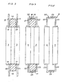
- FIGS. 3 to 6 show schematic plan views of battery cells before and after welding to battery cell pairs.
- FIG. 3 shows a schematic plan view of two battery cells for parallel connection with anvil incorporated an ultrasonic welding system.
- the two lithium-ion battery cells 2 and 3 are not yet electrically connected to a battery cell pair or to a battery cell stack. While protruding from the sides 38 positive pole terminals 22, protrude from the opposite sides 39 of the battery cells 2 and 3 negative pole terminals 23 out. Between the pole terminals 22 and 23, an anvil 40 of an ultrasonic welding system is positioned and the pole terminals 22 and 23 are each bent to the anvil 40, as it FIG. 4 shows.
- FIG. 4 shows a schematic plan view of the battery cells according to FIG. 3 After edging of Polanticiann 22 and 23 on the anvil 40.
- the ends of the pole terminals 22 and 23 are the same pole to each other, so that the positive poles and the negative poles are now closed in parallel to increase the capacity of the battery to be produced .
- An ultrasonic electrode is pressed onto these bent pole terminals 22 and 23, so that a cohesive welded joint 29 is formed, after which the anvil 40 can be pulled out again and the in FIG. 5 shown structure of an upper side of the now paired battery cell stack 8 in parallel circuit 32 results.
- the advantages of this structure have already been discussed at the beginning. Of course, a tap for charge equalization lines can be fixed on such a welded joint.
- FIG. 6 shows a schematic plan view of a series-welded group of battery cells 2 to 7.
- the battery cells 2 to 7 are connected here via their end faces and the pole terminals 22 and 23 protruding therefrom to form a series circuit 33.
- the first two battery cells 2 and 3 are not yet coupled together, but only one anvil 40 of an ultrasonic system is arranged between the positive pole terminal 22 of the battery cell 2 and the negative pole terminal 23 of the battery cell 3.
- the positive pole terminal 22 of the battery cell 3 is already tilted toward one another with the negative pole terminal 23 of the battery cell 4 via another anvil 40, so that these two opposite-pole pole terminals 22 and 23 can be materially connected to one another with the aid of an ultrasonic electrode.
Landscapes
- Chemical & Material Sciences (AREA)
- Chemical Kinetics & Catalysis (AREA)
- Electrochemistry (AREA)
- General Chemical & Material Sciences (AREA)
- Engineering & Computer Science (AREA)
- Manufacturing & Machinery (AREA)
- Power Engineering (AREA)
- Connection Of Batteries Or Terminals (AREA)
- Secondary Cells (AREA)
- Charge And Discharge Circuits For Batteries Or The Like (AREA)
- Battery Mounting, Suspending (AREA)
Claims (20)
- Batterie munie de cellules de batterie (2 à 7), comportant :- une pluralité d'empilements de cellules de batterie (8 à 19) montée en série, un empilement de cellules de batterie (8 à 19) comportant une seule cellule de batterie ou des cellules de batterie (2, 3 ; 4, 5) montées en parallèle ;- des capteurs (20) pour la surveillance de l'état de charge de certaines cellules de batterie (2 à 7) ou de certains empilements de cellules de batterie (8 à 19) ou de certaines paires de cellules de batterie (2, 3 ; 4, 5) ou de certaines paires d'empilements de cellules de batterie (8, 9 ; 10, 11) et- un dispositif d'équilibrage de charge (21) ;le dispositif d'équilibrage de charge (21) comportant un tableau de valeurs cibles de l'état de charge admissible de certaines cellules de batterie (2 à 7) et étant relié aux capteurs pour la surveillance de l'état de charge et comportant des moyens permettant d'interrompre l'équilibrage de charge lorsqu'une valeur cible pour l'état de charge de certaines cellules de batterie (2 à 7) est atteinte, les bornes polaires (22, 23) des cellules de batterie (2 à 7) ou l'empilement de cellules de batterie (8 à 19) étant soudés entre eux par paires à l'aide de surfaces de soudure et des lignes d'équilibrage de la charge étant reliées électriquement aux surfaces de soudure, caractérisée en ce que les bornes polaires (22, 23) soudés par paires avec les lignes d'équilibrage de la charge comportent une liaison supplémentaire soudée par ultrasons, la soudure par ultrasons de cette liaison soudée supplémentaire s'étendant sur une surface de 5 à 50 mm2.
- Batterie selon la revendication 1,
caractérisée en ce que le dispositif d'équilibrage de la charge (21) commande les états de charge des cellules de batterie (2 à 7), de sorte que les états de charge des cellules de batterie (2 à 7) sont identiques entre eux. - Batterie selon la revendication 1 ou 2,
caractérisée en ce qu'une courbe de tension d'état de charge du système global de la batterie (1) est enregistrée dans le dispositif d'équilibrage de la charge (21). - Batterie selon l'une quelconque des revendications précédentes,
caractérisée en ce que le montage en série comprend jusqu'à mille cellules de batterie (2 à 7), de préférence jusqu'à cent cellules de batterie (2 à 7) et la batterie (1) comportant jusqu'à 50 cellules de batterie (2 à 7), de préférence de deux à quatre cellules de batterie (2 à 7) par montage en parallèle. - Batterie selon l'une quelconque des revendications précédentes,
caractérisée en ce que les tolérances de fabrication mécaniques sont compensées lors de la disposition de cellules de batterie dans un boîtier de batterie (30) par les bornes polaires (22, 23) soudés par paires. - Batterie selon la revendication 5,
caractérisée en ce que les cellules de batterie sont reliées électriquement par un faisceau de câbles (25) ou par un flexboard ou par un circuit imprimé avec des CSM (cell supervision modules) ou avec des CSC (cell supervision circuits). - Batterie selon l'une quelconque des revendications précédentes,
caractérisée en ce que la batterie (1) comporte des cellules lithium-ion prismatiques. - Batterie selon l'une quelconque des revendications précédentes,
caractérisée en ce que la batterie (1) comporte des modules de surveillance de cellules (26, 27), un module de surveillance de module (26) comprenant un circuit intégré avec des circuits de surveillances de cellules (28). - Batterie selon l'une quelconque des revendications précédentes,
caractérisée en ce que les bornes polaires (22, 23) des cellules de batterie (2 à 7) sont soudés par paires par ultrasons. - Batterie selon la revendication 9,
caractérisée en ce que plusieurs bornes polaires (22, 23) soudés par paires sont soudés par ultrasons aux principales bornes soudées plusieurs fois. - Batterie selon la revendication 9 ou 10,
caractérisée en ce que des capteurs de surveillance des cellules de batterie sont soudés par ultrasons aux bornes polaires (22, 23) soudés par paires. - Procédé de fabrication d'une batterie (1) dotée d'une pluralité de cellules de batterie (2 à 7), ce procédé comportant les étapes de procédé suivantes :- insertion de cellules de batterie dans un boîtier de batterie (30) ;- établissement par paires de liaisons soudées (29) entre les bornes polaires (22, 23) des cellules de batterie (2 à 7), les bornes polaires (22) de cellules de batterie identiques étant soudés entre eux sur toute leur surface lors de montages en parallèle ou de bornes polaires (22, 23) de cellules de batterie de polarités inverses pour des montages en série ;- établissement d'un faisceau de câbles ou d'un flexboard ou d'un circuit imprimé avec des circuits de surveillance de batterie (28) ou des CSC ou des modules de surveillance des cellules de batterie (26, 27) ou des CSM d'un dispositif d'équilibrage de la charge avec des lignes d'équilibrage de la charge (24), qui comportent des capteurs ;- soudure des capteurs des lignes d'équilibrage de la charge (24) pour la surveillance individuelle des cellules de batterie aux liaisons soudées par paires des bornes polaires (22, 23) ;- raccordement des bornes externes de la batterie (31) aux bornes polaires des cellules terminales de la batterie, caractérisée en ce que, lors de la soudure des capteurs des lignes d'équilibrage de la charge, une soudure par ultrasons présentant une surface de 5 à 50 mm2 est prévue.
- Procédé selon la revendication 12,
caractérisé en ce que le dispositif d'équilibrage de la charge (21) modifie les états de charge des cellules de batterie (2 à 7) de sorte que les états de charge des cellules de batterie (2 à 7) sont équilibrés entre eux. - Procédé selon la revendication 12 ou la revendication 13,
caractérisé en ce qu'une courbe de tension d'état de charge du système global de la batterie (1) est enregistrée dans le dispositif d'équilibrage de la charge (21). - Procédé selon l'une quelconque des revendications 12 à 14,
caractérisé en ce que jusqu'à mille cellules de batterie (2 à 7), de préférence jusqu'à cent cellules de batterie (2 à 7) sont soudées selon un montage en série (33) et jusqu'à 50 cellules de batterie (2 à 7), de préférence de deux à quatre cellules de batterie (2 à 4) sont soudées entre elles selon un montage en parallèle (32). - Procédé selon l'une quelconque des revendications 12 à 15,
caractérisé en ce que chaque cellule de batterie (2 à 7) est reliée par un faisceau de câbles (25), par un flexboard ou par un circuit imprimé pour la détection et/ou l'équilibrage de l'état de charge de la cellule de batterie (2 à 7) avec des CSM ou des CSC. - Procédé selon l'une quelconque des revendications 12 à 16,
caractérisé en ce que, en tant que cellules de batterie (2 à 7), des cellules lithium-ion sont utilisées sous la forme de cellules plates dans un emballage en film composite d'aluminium, dont les états de charge sont détectés et équilibrés par des circuits de surveillance des cellules (28). - Procédé selon l'une quelconque des revendications 12 à 17,
caractérisé en ce que les bornes polaires (22, 23) de cellules de batterie (2 à 7) sont soudés par paires par ultrasons. - Procédé selon la revendication 18,
caractérisé en ce que plusieurs bornes polaires (22, 23) soudés par paires sont soudés par ultrasons aux principales bornes soudées plusieurs fois. - Procédé selon la revendication 18 ou la revendication 19,
caractérisé en ce que des capteurs pour une surveillance des cellules de batterie sont soudés par ultrasons sur les bornes polaires (22, 23) soudées par paires.
Applications Claiming Priority (2)
| Application Number | Priority Date | Filing Date | Title |
|---|---|---|---|
| DE102008027417 | 2008-06-09 | ||
| PCT/DE2009/000768 WO2009149690A1 (fr) | 2008-06-09 | 2009-06-04 | Batterie comprenant des cellules de batterie et un dispositif d’équilibrage de la charge et des bornes polaires soudées entre elles |
Publications (2)
| Publication Number | Publication Date |
|---|---|
| EP2283537A1 EP2283537A1 (fr) | 2011-02-16 |
| EP2283537B1 true EP2283537B1 (fr) | 2014-02-12 |
Family
ID=41057309
Family Applications (1)
| Application Number | Title | Priority Date | Filing Date |
|---|---|---|---|
| EP09761312.9A Active EP2283537B1 (fr) | 2008-06-09 | 2009-06-04 | Batterie comprenant des cellules de batterie et un dispositif d équilibrage de la charge et des bornes polaires soudées entre elles |
Country Status (5)
| Country | Link |
|---|---|
| US (1) | US8564244B2 (fr) |
| EP (1) | EP2283537B1 (fr) |
| JP (1) | JP5483034B2 (fr) |
| DE (1) | DE112009000464A5 (fr) |
| WO (1) | WO2009149690A1 (fr) |
Cited By (2)
| Publication number | Priority date | Publication date | Assignee | Title |
|---|---|---|---|---|
| CN103260936A (zh) * | 2010-08-30 | 2013-08-21 | 罗伯特·博世有限公司 | 一种用于均衡具有多个蓄电池单元的蓄电池的充电状态的方法以及一种相应的蓄电池管理系统和蓄电池 |
| DE102019113877B4 (de) * | 2018-07-09 | 2025-11-13 | GM Global Technology Operations LLC | Batteriemodul mit aktivem zellausgleich unter verwendung eines energiespeicherelements und zweier ebenen von schaltern |
Families Citing this family (16)
| Publication number | Priority date | Publication date | Assignee | Title |
|---|---|---|---|---|
| DE102009058861B4 (de) * | 2009-12-18 | 2020-10-22 | Samsung Sdi Co., Ltd. | Akkumulator |
| DE102010023934A1 (de) * | 2010-06-16 | 2011-12-22 | Continental Automotive Gmbh | Elektrisches System bzw. Energiespeichersystem mit Mittelspannungsabgriff |
| US8816639B2 (en) * | 2011-06-02 | 2014-08-26 | Aerojet Rocketdyne Of De, Inc. | Charge balancing topology |
| DE102012210262A1 (de) | 2011-11-18 | 2013-05-23 | Robert Bosch Gmbh | Batterie mit einer Batteriezelle mit externem und integriertem Temperatursensor und Verfahren zum Betrieb der Batterie |
| DE102011086620A1 (de) | 2011-11-18 | 2013-05-23 | Robert Bosch Gmbh | Verfahren zum Überwachen einer Batterie |
| DE102011121488B4 (de) | 2011-12-16 | 2020-01-23 | Audi Ag | Batterie für ein Kraftfahrzeug |
| DE102012202079A1 (de) | 2012-02-13 | 2013-08-14 | Robert Bosch Gmbh | Verfahren zum Überwachen einer Batterie |
| TWI496339B (zh) * | 2013-08-20 | 2015-08-11 | Metal Ind Res & Dev Ct | 具有電源單元或電池群組的電子裝置 |
| KR101551000B1 (ko) * | 2013-12-12 | 2015-09-07 | 현대자동차주식회사 | 전기자동차의 고전압배터리 시스템 |
| DE102014200188A1 (de) * | 2014-01-09 | 2015-07-09 | Robert Bosch Gmbh | Kabelbaum zum elektrisch leitfähigen Verbinden und elektronischen Überwachen mehrerer Batteriezellen |
| US10062931B2 (en) | 2015-04-22 | 2018-08-28 | Johnson Controls Technology Company | Welding process for battery module components |
| CN110085776B (zh) * | 2018-01-26 | 2022-05-24 | 微宏动力系统(湖州)有限公司 | 一种电池 |
| FR3081225B1 (fr) * | 2018-05-18 | 2020-06-05 | E-Xteq Europe | Dispositif de controle et d'assistance du nivellement de charge d'un module de batterie, procede et kit correspondants |
| US11881735B2 (en) * | 2018-07-11 | 2024-01-23 | Cummins Inc. | Integration of second-use of Li-ion batteries in power generation |
| CN111613762B (zh) * | 2019-02-22 | 2022-06-10 | Oppo广东移动通信有限公司 | 电池组、电子设备和充放电控制方法 |
| US20230336015A1 (en) * | 2022-04-15 | 2023-10-19 | Walter A. Tormasi | Circuit-switchable electrochemical network |
Family Cites Families (16)
| Publication number | Priority date | Publication date | Assignee | Title |
|---|---|---|---|---|
| US5825155A (en) * | 1993-08-09 | 1998-10-20 | Kabushiki Kaisha Toshiba | Battery set structure and charge/ discharge control apparatus for lithium-ion battery |
| US5504415A (en) * | 1993-12-03 | 1996-04-02 | Electronic Power Technology, Inc. | Method and apparatus for automatic equalization of series-connected batteries |
| DE19705192A1 (de) * | 1996-02-29 | 1997-10-30 | Mikron Ges Fuer Integrierte Mi | Batterie-Überwachungssystem |
| US6146778A (en) | 1997-07-25 | 2000-11-14 | 3M Innovative Properties Company | Solid-state energy storage module employing integrated interconnect board |
| JPH11299122A (ja) * | 1998-02-10 | 1999-10-29 | Denso Corp | 充電状態制御方法及び装置 |
| US6190426B1 (en) * | 1998-12-17 | 2001-02-20 | Moltech Corporation | Methods of preparing prismatic cells |
| GB9900396D0 (en) | 1999-01-08 | 1999-02-24 | Danionics As | Arrangements of electrochemical cells |
| JP2002231300A (ja) | 2000-11-30 | 2002-08-16 | Matsushita Electric Ind Co Ltd | 角形密閉式電池及びその製造方法 |
| JP2004515044A (ja) * | 2000-11-30 | 2004-05-20 | コーニンクレッカ フィリップス エレクトロニクス エヌ ヴィ | 再充電可能なバッテリーの充電状態及び残り使用時間を予測する方法 |
| US6858345B2 (en) | 2002-04-09 | 2005-02-22 | The University Of Chicago | Wound bipolar lithium polymer batteries |
| JP4483162B2 (ja) * | 2002-08-22 | 2010-06-16 | 日産自動車株式会社 | 積層型電池、組電池、電池モジュール並びに電気自動車 |
| JP4111043B2 (ja) * | 2003-04-18 | 2008-07-02 | 日産自動車株式会社 | バイポーラ二次電池 |
| US7417405B2 (en) * | 2004-10-04 | 2008-08-26 | Black & Decker Inc. | Battery monitoring arrangement having an integrated circuit with logic controller in a battery pack |
| JP4655593B2 (ja) * | 2004-11-11 | 2011-03-23 | 日産自動車株式会社 | バイポーラ電池 |
| CA2531295C (fr) * | 2004-12-22 | 2013-10-22 | Odyne Corporation | Systeme de charge de batterie faisant appel a une porteuse sur cable d'alimentation et a un systeme de gestion d'accumulateurs |
| JP5110842B2 (ja) | 2006-09-30 | 2012-12-26 | 三洋電機株式会社 | 組電池とその製造方法 |
-
2009
- 2009-06-04 JP JP2011513862A patent/JP5483034B2/ja active Active
- 2009-06-04 WO PCT/DE2009/000768 patent/WO2009149690A1/fr not_active Ceased
- 2009-06-04 EP EP09761312.9A patent/EP2283537B1/fr active Active
- 2009-06-04 US US12/995,484 patent/US8564244B2/en not_active Expired - Fee Related
- 2009-06-04 DE DE112009000464T patent/DE112009000464A5/de not_active Withdrawn
Cited By (3)
| Publication number | Priority date | Publication date | Assignee | Title |
|---|---|---|---|---|
| CN103260936A (zh) * | 2010-08-30 | 2013-08-21 | 罗伯特·博世有限公司 | 一种用于均衡具有多个蓄电池单元的蓄电池的充电状态的方法以及一种相应的蓄电池管理系统和蓄电池 |
| CN103260936B (zh) * | 2010-08-30 | 2016-01-20 | 罗伯特·博世有限公司 | 一种用于均衡具有多个蓄电池单元的蓄电池的充电状态的方法以及一种相应的蓄电池管理系统和蓄电池 |
| DE102019113877B4 (de) * | 2018-07-09 | 2025-11-13 | GM Global Technology Operations LLC | Batteriemodul mit aktivem zellausgleich unter verwendung eines energiespeicherelements und zweier ebenen von schaltern |
Also Published As
| Publication number | Publication date |
|---|---|
| US8564244B2 (en) | 2013-10-22 |
| DE112009000464A5 (de) | 2010-11-25 |
| JP2011524731A (ja) | 2011-09-01 |
| US20110127961A1 (en) | 2011-06-02 |
| WO2009149690A1 (fr) | 2009-12-17 |
| EP2283537A1 (fr) | 2011-02-16 |
| JP5483034B2 (ja) | 2014-05-07 |
Similar Documents
| Publication | Publication Date | Title |
|---|---|---|
| EP2283537A1 (fr) | Batterie comprenant des cellules de batterie et un dispositif d équilibrage de la charge et des bornes polaires soudées entre elles | |
| DE19810746B4 (de) | Platine mit einer Schaltung zur Überwachung einer mehrzelligen Akkumulatorenbatterie | |
| EP2368304B1 (fr) | Dispositif de stockage d'énergie et procédé pour faire fonctionner un tel dispositif | |
| DE102006061270B4 (de) | Batteriepack und Batteriemodul | |
| DE69836140T2 (de) | Festkörper-Energiespeichermodul mit integrierter Leiterplatte | |
| EP2639857B1 (fr) | Système de liaison pour un dispositif d'accumulation d'énergie et dispositif d'accumulation d'énergie doté du système de liaison | |
| EP2646785B1 (fr) | Dispositif permettant de détecter la température d'un accumulateur d'énergie | |
| EP3363059B1 (fr) | Module de cellules pour le stockage d'énergie éléctrique, batterie de cellules, et boîte | |
| DE102011115550A1 (de) | Lithium-Ionen-Batterie | |
| DE19611776A1 (de) | Batterie | |
| DE102016208420B4 (de) | Anordnung mit multifunktionalem Anschluss für Energiespeicherzellen oder Energieverbraucher | |
| DE102011076919A1 (de) | Batteriezelle, Batterie oder Batteriezellenmodul, Verfahren zur Herstellung einer Batteriezelle und Kraftfahrzeug | |
| DE102015113374A1 (de) | Integration einer spannungserfassungs-leiterbahnsicherung in eine batterieverbindungsplatine | |
| EP3161896B1 (fr) | Élément de liaison électrique pour module de batterie | |
| DE102011115452A1 (de) | Lithium-Ionen-Batterie | |
| DE102008050437B4 (de) | Skalierbare Kraftfahrzeugbatterie und Verfahren zur Herstellung dafür | |
| DE102016106620A1 (de) | Elektrische Hochstrom-Fügestelle, die eine Teilmontage beseitigt | |
| EP3631877A2 (fr) | Ensemble de cellules électrochimiques, module d'accumulation d'énergie et procédé pour l'assemblage de ceux-ci | |
| DE102022107491A1 (de) | Zellmodul mit einer Messeinrichtung zur Erkennung einer Verformung und Beschädigung eines Zellmodulrahmens | |
| DE102013201358A1 (de) | Elektrischer Verbinder für Batteriezellen, -Module und -SubUnits, Batteriepack sowie Kraftfahrzeug | |
| DE102009035469A1 (de) | Batterie mit einer Zellüberwachungsvorrichtung | |
| WO2013023850A1 (fr) | Module de batteries avec détection d'état de batterie et véhicule automobile équipé d'une batterie lithium-ion | |
| EP4550518A1 (fr) | Batterie comprenant un boîtier et une pluralité d'éléments accumulateurs d'énergie électrochimique rechargeables disposés à l'intérieur de celle-ci | |
| DE102013002341A1 (de) | Vorrichtung zur elektrisch leitfähigen Verbindung eines Zell-Controllers mit einer Mehrzahl elektrischer Speicherzellen | |
| DE102022132938A1 (de) | Elektrischer Energiespeicher mit zellpaketintegrierter Speicherelektronik |
Legal Events
| Date | Code | Title | Description |
|---|---|---|---|
| PUAI | Public reference made under article 153(3) epc to a published international application that has entered the european phase |
Free format text: ORIGINAL CODE: 0009012 |
|
| 17P | Request for examination filed |
Effective date: 20100826 |
|
| AK | Designated contracting states |
Kind code of ref document: A1 Designated state(s): AT BE BG CH CY CZ DE DK EE ES FI FR GB GR HR HU IE IS IT LI LT LU LV MC MK MT NL NO PL PT RO SE SI SK TR |
|
| AX | Request for extension of the european patent |
Extension state: AL BA RS |
|
| DAX | Request for extension of the european patent (deleted) | ||
| 17Q | First examination report despatched |
Effective date: 20111102 |
|
| REG | Reference to a national code |
Ref country code: DE Ref legal event code: R079 Ref document number: 502009008786 Country of ref document: DE Free format text: PREVIOUS MAIN CLASS: H01M0010420000 Ipc: H01M0002200000 |
|
| RIC1 | Information provided on ipc code assigned before grant |
Ipc: H01M 10/04 20060101ALI20120229BHEP Ipc: H01M 2/20 20060101AFI20120229BHEP Ipc: H01M 10/48 20060101ALI20120229BHEP Ipc: H02J 7/00 20060101ALI20120229BHEP Ipc: H01M 10/42 20060101ALI20120229BHEP Ipc: H01M 10/44 20060101ALI20120229BHEP |
|
| GRAP | Despatch of communication of intention to grant a patent |
Free format text: ORIGINAL CODE: EPIDOSNIGR1 |
|
| INTG | Intention to grant announced |
Effective date: 20130913 |
|
| GRAS | Grant fee paid |
Free format text: ORIGINAL CODE: EPIDOSNIGR3 |
|
| GRAA | (expected) grant |
Free format text: ORIGINAL CODE: 0009210 |
|
| AK | Designated contracting states |
Kind code of ref document: B1 Designated state(s): AT BE BG CH CY CZ DE DK EE ES FI FR GB GR HR HU IE IS IT LI LT LU LV MC MK MT NL NO PL PT RO SE SI SK TR |
|
| REG | Reference to a national code |
Ref country code: GB Ref legal event code: FG4D Free format text: NOT ENGLISH |
|
| REG | Reference to a national code |
Ref country code: CH Ref legal event code: EP |
|
| REG | Reference to a national code |
Ref country code: AT Ref legal event code: REF Ref document number: 652478 Country of ref document: AT Kind code of ref document: T Effective date: 20140215 |
|
| REG | Reference to a national code |
Ref country code: DE Ref legal event code: R096 Ref document number: 502009008786 Country of ref document: DE Effective date: 20140320 |
|
| REG | Reference to a national code |
Ref country code: IE Ref legal event code: FG4D Free format text: LANGUAGE OF EP DOCUMENT: GERMAN |
|
| REG | Reference to a national code |
Ref country code: NL Ref legal event code: VDEP Effective date: 20140212 |
|
| REG | Reference to a national code |
Ref country code: LT Ref legal event code: MG4D |
|
| PG25 | Lapsed in a contracting state [announced via postgrant information from national office to epo] |
Ref country code: NO Free format text: LAPSE BECAUSE OF FAILURE TO SUBMIT A TRANSLATION OF THE DESCRIPTION OR TO PAY THE FEE WITHIN THE PRESCRIBED TIME-LIMIT Effective date: 20140512 Ref country code: LT Free format text: LAPSE BECAUSE OF FAILURE TO SUBMIT A TRANSLATION OF THE DESCRIPTION OR TO PAY THE FEE WITHIN THE PRESCRIBED TIME-LIMIT Effective date: 20140212 Ref country code: IS Free format text: LAPSE BECAUSE OF FAILURE TO SUBMIT A TRANSLATION OF THE DESCRIPTION OR TO PAY THE FEE WITHIN THE PRESCRIBED TIME-LIMIT Effective date: 20140612 |
|
| PG25 | Lapsed in a contracting state [announced via postgrant information from national office to epo] |
Ref country code: CY Free format text: LAPSE BECAUSE OF FAILURE TO SUBMIT A TRANSLATION OF THE DESCRIPTION OR TO PAY THE FEE WITHIN THE PRESCRIBED TIME-LIMIT Effective date: 20140212 Ref country code: PT Free format text: LAPSE BECAUSE OF FAILURE TO SUBMIT A TRANSLATION OF THE DESCRIPTION OR TO PAY THE FEE WITHIN THE PRESCRIBED TIME-LIMIT Effective date: 20140612 Ref country code: SE Free format text: LAPSE BECAUSE OF FAILURE TO SUBMIT A TRANSLATION OF THE DESCRIPTION OR TO PAY THE FEE WITHIN THE PRESCRIBED TIME-LIMIT Effective date: 20140212 Ref country code: ES Free format text: LAPSE BECAUSE OF FAILURE TO SUBMIT A TRANSLATION OF THE DESCRIPTION OR TO PAY THE FEE WITHIN THE PRESCRIBED TIME-LIMIT Effective date: 20140212 Ref country code: NL Free format text: LAPSE BECAUSE OF FAILURE TO SUBMIT A TRANSLATION OF THE DESCRIPTION OR TO PAY THE FEE WITHIN THE PRESCRIBED TIME-LIMIT Effective date: 20140212 Ref country code: FI Free format text: LAPSE BECAUSE OF FAILURE TO SUBMIT A TRANSLATION OF THE DESCRIPTION OR TO PAY THE FEE WITHIN THE PRESCRIBED TIME-LIMIT Effective date: 20140212 |
|
| PG25 | Lapsed in a contracting state [announced via postgrant information from national office to epo] |
Ref country code: HR Free format text: LAPSE BECAUSE OF FAILURE TO SUBMIT A TRANSLATION OF THE DESCRIPTION OR TO PAY THE FEE WITHIN THE PRESCRIBED TIME-LIMIT Effective date: 20140212 Ref country code: LV Free format text: LAPSE BECAUSE OF FAILURE TO SUBMIT A TRANSLATION OF THE DESCRIPTION OR TO PAY THE FEE WITHIN THE PRESCRIBED TIME-LIMIT Effective date: 20140212 |
|
| PG25 | Lapsed in a contracting state [announced via postgrant information from national office to epo] |
Ref country code: CZ Free format text: LAPSE BECAUSE OF FAILURE TO SUBMIT A TRANSLATION OF THE DESCRIPTION OR TO PAY THE FEE WITHIN THE PRESCRIBED TIME-LIMIT Effective date: 20140212 Ref country code: EE Free format text: LAPSE BECAUSE OF FAILURE TO SUBMIT A TRANSLATION OF THE DESCRIPTION OR TO PAY THE FEE WITHIN THE PRESCRIBED TIME-LIMIT Effective date: 20140212 Ref country code: RO Free format text: LAPSE BECAUSE OF FAILURE TO SUBMIT A TRANSLATION OF THE DESCRIPTION OR TO PAY THE FEE WITHIN THE PRESCRIBED TIME-LIMIT Effective date: 20140212 Ref country code: DK Free format text: LAPSE BECAUSE OF FAILURE TO SUBMIT A TRANSLATION OF THE DESCRIPTION OR TO PAY THE FEE WITHIN THE PRESCRIBED TIME-LIMIT Effective date: 20140212 |
|
| REG | Reference to a national code |
Ref country code: DE Ref legal event code: R097 Ref document number: 502009008786 Country of ref document: DE |
|
| PG25 | Lapsed in a contracting state [announced via postgrant information from national office to epo] |
Ref country code: SK Free format text: LAPSE BECAUSE OF FAILURE TO SUBMIT A TRANSLATION OF THE DESCRIPTION OR TO PAY THE FEE WITHIN THE PRESCRIBED TIME-LIMIT Effective date: 20140212 Ref country code: PL Free format text: LAPSE BECAUSE OF FAILURE TO SUBMIT A TRANSLATION OF THE DESCRIPTION OR TO PAY THE FEE WITHIN THE PRESCRIBED TIME-LIMIT Effective date: 20140212 |
|
| PLBE | No opposition filed within time limit |
Free format text: ORIGINAL CODE: 0009261 |
|
| STAA | Information on the status of an ep patent application or granted ep patent |
Free format text: STATUS: NO OPPOSITION FILED WITHIN TIME LIMIT |
|
| 26N | No opposition filed |
Effective date: 20141113 |
|
| PG25 | Lapsed in a contracting state [announced via postgrant information from national office to epo] |
Ref country code: MC Free format text: LAPSE BECAUSE OF FAILURE TO SUBMIT A TRANSLATION OF THE DESCRIPTION OR TO PAY THE FEE WITHIN THE PRESCRIBED TIME-LIMIT Effective date: 20140212 Ref country code: LU Free format text: LAPSE BECAUSE OF FAILURE TO SUBMIT A TRANSLATION OF THE DESCRIPTION OR TO PAY THE FEE WITHIN THE PRESCRIBED TIME-LIMIT Effective date: 20140604 |
|
| REG | Reference to a national code |
Ref country code: CH Ref legal event code: PL |
|
| REG | Reference to a national code |
Ref country code: DE Ref legal event code: R097 Ref document number: 502009008786 Country of ref document: DE Effective date: 20141113 |
|
| REG | Reference to a national code |
Ref country code: IE Ref legal event code: MM4A |
|
| PG25 | Lapsed in a contracting state [announced via postgrant information from national office to epo] |
Ref country code: IT Free format text: LAPSE BECAUSE OF FAILURE TO SUBMIT A TRANSLATION OF THE DESCRIPTION OR TO PAY THE FEE WITHIN THE PRESCRIBED TIME-LIMIT Effective date: 20140212 |
|
| PG25 | Lapsed in a contracting state [announced via postgrant information from national office to epo] |
Ref country code: IE Free format text: LAPSE BECAUSE OF NON-PAYMENT OF DUE FEES Effective date: 20140604 Ref country code: LI Free format text: LAPSE BECAUSE OF NON-PAYMENT OF DUE FEES Effective date: 20140630 Ref country code: CH Free format text: LAPSE BECAUSE OF NON-PAYMENT OF DUE FEES Effective date: 20140630 |
|
| PG25 | Lapsed in a contracting state [announced via postgrant information from national office to epo] |
Ref country code: SI Free format text: LAPSE BECAUSE OF FAILURE TO SUBMIT A TRANSLATION OF THE DESCRIPTION OR TO PAY THE FEE WITHIN THE PRESCRIBED TIME-LIMIT Effective date: 20140212 |
|
| REG | Reference to a national code |
Ref country code: AT Ref legal event code: MM01 Ref document number: 652478 Country of ref document: AT Kind code of ref document: T Effective date: 20140604 |
|
| PG25 | Lapsed in a contracting state [announced via postgrant information from national office to epo] |
Ref country code: AT Free format text: LAPSE BECAUSE OF NON-PAYMENT OF DUE FEES Effective date: 20140604 |
|
| PG25 | Lapsed in a contracting state [announced via postgrant information from national office to epo] |
Ref country code: MT Free format text: LAPSE BECAUSE OF FAILURE TO SUBMIT A TRANSLATION OF THE DESCRIPTION OR TO PAY THE FEE WITHIN THE PRESCRIBED TIME-LIMIT Effective date: 20140212 |
|
| REG | Reference to a national code |
Ref country code: FR Ref legal event code: PLFP Year of fee payment: 8 |
|
| PG25 | Lapsed in a contracting state [announced via postgrant information from national office to epo] |
Ref country code: GR Free format text: LAPSE BECAUSE OF FAILURE TO SUBMIT A TRANSLATION OF THE DESCRIPTION OR TO PAY THE FEE WITHIN THE PRESCRIBED TIME-LIMIT Effective date: 20140513 Ref country code: BG Free format text: LAPSE BECAUSE OF FAILURE TO SUBMIT A TRANSLATION OF THE DESCRIPTION OR TO PAY THE FEE WITHIN THE PRESCRIBED TIME-LIMIT Effective date: 20140212 |
|
| PG25 | Lapsed in a contracting state [announced via postgrant information from national office to epo] |
Ref country code: TR Free format text: LAPSE BECAUSE OF FAILURE TO SUBMIT A TRANSLATION OF THE DESCRIPTION OR TO PAY THE FEE WITHIN THE PRESCRIBED TIME-LIMIT Effective date: 20140212 Ref country code: HU Free format text: LAPSE BECAUSE OF FAILURE TO SUBMIT A TRANSLATION OF THE DESCRIPTION OR TO PAY THE FEE WITHIN THE PRESCRIBED TIME-LIMIT; INVALID AB INITIO Effective date: 20090604 Ref country code: BE Free format text: LAPSE BECAUSE OF FAILURE TO SUBMIT A TRANSLATION OF THE DESCRIPTION OR TO PAY THE FEE WITHIN THE PRESCRIBED TIME-LIMIT Effective date: 20140630 |
|
| REG | Reference to a national code |
Ref country code: FR Ref legal event code: PLFP Year of fee payment: 9 |
|
| REG | Reference to a national code |
Ref country code: FR Ref legal event code: PLFP Year of fee payment: 10 |
|
| PG25 | Lapsed in a contracting state [announced via postgrant information from national office to epo] |
Ref country code: MK Free format text: LAPSE BECAUSE OF FAILURE TO SUBMIT A TRANSLATION OF THE DESCRIPTION OR TO PAY THE FEE WITHIN THE PRESCRIBED TIME-LIMIT Effective date: 20140212 |
|
| REG | Reference to a national code |
Ref country code: DE Ref legal event code: R079 Ref document number: 502009008786 Country of ref document: DE Free format text: PREVIOUS MAIN CLASS: H01M0002200000 Ipc: H01M0050500000 |
|
| REG | Reference to a national code |
Ref country code: DE Ref legal event code: R081 Ref document number: 502009008786 Country of ref document: DE Owner name: SCHAEFFLER TECHNOLOGIES AG & CO. KG, DE Free format text: FORMER OWNER: TEMIC AUTOMOTIVE ELECTRIC MOTORS GMBH, 10553 BERLIN, DE Ref country code: DE Ref legal event code: R081 Ref document number: 502009008786 Country of ref document: DE Owner name: VITESCO TECHNOLOGIES GERMANY GMBH, DE Free format text: FORMER OWNER: TEMIC AUTOMOTIVE ELECTRIC MOTORS GMBH, 10553 BERLIN, DE |
|
| REG | Reference to a national code |
Ref country code: DE Ref legal event code: R084 Ref document number: 502009008786 Country of ref document: DE |
|
| REG | Reference to a national code |
Ref country code: DE Ref legal event code: R081 Ref document number: 502009008786 Country of ref document: DE Owner name: SCHAEFFLER TECHNOLOGIES AG & CO. KG, DE Free format text: FORMER OWNER: VITESCO TECHNOLOGIES GERMANY GMBH, 30165 HANNOVER, DE Ref country code: DE Ref legal event code: R081 Ref document number: 502009008786 Country of ref document: DE Owner name: VITESCO TECHNOLOGIES GERMANY GMBH, DE Free format text: FORMER OWNER: VITESCO TECHNOLOGIES GERMANY GMBH, 30165 HANNOVER, DE |
|
| P01 | Opt-out of the competence of the unified patent court (upc) registered |
Effective date: 20230530 |
|
| REG | Reference to a national code |
Ref country code: GB Ref legal event code: 732E Free format text: REGISTERED BETWEEN 20230713 AND 20230719 |
|
| REG | Reference to a national code |
Ref country code: DE Ref legal event code: R081 Ref document number: 502009008786 Country of ref document: DE Owner name: SCHAEFFLER TECHNOLOGIES AG & CO. KG, DE Free format text: FORMER OWNER: VITESCO TECHNOLOGIES GERMANY GMBH, REGENSBURG, DE |
|
| PGFP | Annual fee paid to national office [announced via postgrant information from national office to epo] |
Ref country code: DE Payment date: 20250630 Year of fee payment: 17 |
|
| PGFP | Annual fee paid to national office [announced via postgrant information from national office to epo] |
Ref country code: GB Payment date: 20250618 Year of fee payment: 17 |
|
| PGFP | Annual fee paid to national office [announced via postgrant information from national office to epo] |
Ref country code: FR Payment date: 20250624 Year of fee payment: 17 |