EP2283671B1 - Procédé et appareil relatifs à la détection de spectre - Google Patents
Procédé et appareil relatifs à la détection de spectre Download PDFInfo
- Publication number
- EP2283671B1 EP2283671B1 EP09758626.7A EP09758626A EP2283671B1 EP 2283671 B1 EP2283671 B1 EP 2283671B1 EP 09758626 A EP09758626 A EP 09758626A EP 2283671 B1 EP2283671 B1 EP 2283671B1
- Authority
- EP
- European Patent Office
- Prior art keywords
- sensors
- sensor
- spectrum
- correlation
- sensing
- Prior art date
- Legal status (The legal status is an assumption and is not a legal conclusion. Google has not performed a legal analysis and makes no representation as to the accuracy of the status listed.)
- Active
Links
- 238000001228 spectrum Methods 0.000 title claims description 102
- 238000000034 method Methods 0.000 title claims description 69
- 238000005457 optimization Methods 0.000 claims description 25
- 238000013459 approach Methods 0.000 claims description 10
- 238000000638 solvent extraction Methods 0.000 claims description 10
- 238000005314 correlation function Methods 0.000 claims description 9
- 239000013598 vector Substances 0.000 claims description 7
- 230000001143 conditioned effect Effects 0.000 claims description 2
- 238000004422 calculation algorithm Methods 0.000 description 29
- 230000006870 function Effects 0.000 description 17
- 238000004891 communication Methods 0.000 description 14
- 230000000875 corresponding effect Effects 0.000 description 14
- 238000010586 diagram Methods 0.000 description 11
- 230000001413 cellular effect Effects 0.000 description 7
- 230000008569 process Effects 0.000 description 7
- 230000005540 biological transmission Effects 0.000 description 6
- 238000005562 fading Methods 0.000 description 6
- 238000001514 detection method Methods 0.000 description 5
- 239000011159 matrix material Substances 0.000 description 5
- 230000004044 response Effects 0.000 description 5
- 230000000694 effects Effects 0.000 description 4
- 230000009467 reduction Effects 0.000 description 4
- 230000008901 benefit Effects 0.000 description 3
- 230000002596 correlated effect Effects 0.000 description 3
- 230000007423 decrease Effects 0.000 description 3
- 238000012545 processing Methods 0.000 description 3
- 238000011160 research Methods 0.000 description 3
- 238000000926 separation method Methods 0.000 description 3
- 230000003595 spectral effect Effects 0.000 description 3
- 238000005259 measurement Methods 0.000 description 2
- 238000012986 modification Methods 0.000 description 2
- 230000004048 modification Effects 0.000 description 2
- 238000005192 partition Methods 0.000 description 2
- 238000004088 simulation Methods 0.000 description 2
- 230000009897 systematic effect Effects 0.000 description 2
- 238000007792 addition Methods 0.000 description 1
- 230000033228 biological regulation Effects 0.000 description 1
- 238000004364 calculation method Methods 0.000 description 1
- 230000008859 change Effects 0.000 description 1
- 230000001149 cognitive effect Effects 0.000 description 1
- 230000000295 complement effect Effects 0.000 description 1
- 230000001276 controlling effect Effects 0.000 description 1
- 230000001419 dependent effect Effects 0.000 description 1
- 238000013461 design Methods 0.000 description 1
- 238000005265 energy consumption Methods 0.000 description 1
- 238000005516 engineering process Methods 0.000 description 1
- 238000011156 evaluation Methods 0.000 description 1
- 230000000977 initiatory effect Effects 0.000 description 1
- 238000010295 mobile communication Methods 0.000 description 1
- 238000012544 monitoring process Methods 0.000 description 1
- 230000001105 regulatory effect Effects 0.000 description 1
- 230000011664 signaling Effects 0.000 description 1
- 238000012360 testing method Methods 0.000 description 1
- 238000012546 transfer Methods 0.000 description 1
- 230000001960 triggered effect Effects 0.000 description 1
Images

Classifications
-
- H—ELECTRICITY
- H04—ELECTRIC COMMUNICATION TECHNIQUE
- H04W—WIRELESS COMMUNICATION NETWORKS
- H04W24/00—Supervisory, monitoring or testing arrangements
- H04W24/08—Testing, supervising or monitoring using real traffic
-
- H—ELECTRICITY
- H04—ELECTRIC COMMUNICATION TECHNIQUE
- H04W—WIRELESS COMMUNICATION NETWORKS
- H04W24/00—Supervisory, monitoring or testing arrangements
-
- H—ELECTRICITY
- H04—ELECTRIC COMMUNICATION TECHNIQUE
- H04W—WIRELESS COMMUNICATION NETWORKS
- H04W4/00—Services specially adapted for wireless communication networks; Facilities therefor
- H04W4/06—Selective distribution of broadcast services, e.g. multimedia broadcast multicast service [MBMS]; Services to user groups; One-way selective calling services
- H04W4/08—User group management
-
- H—ELECTRICITY
- H04—ELECTRIC COMMUNICATION TECHNIQUE
- H04W—WIRELESS COMMUNICATION NETWORKS
- H04W88/00—Devices specially adapted for wireless communication networks, e.g. terminals, base stations or access point devices
- H04W88/02—Terminal devices
Definitions
- the present invention pertains to the field of radio communications, and in particular to the part of this field where spectrum utilisation is based on cooperative spectrum sensing.
- Dynamic Spectrum Access which describes spectrum access where radio units are not limited to using only a specific spectrum band (such as their licensed spectrum), but rather adapt the spectrum they use depending on conditions such as estimated throughput and latency requirements, spectrum availability etc. For instance, a cellular system suffering from high load in its own licensed spectrum could dynamically access spectral bands owned by some other licensee to temporarily increase its throughput, as long as it does not cause unacceptable interference to the primary system, or a network of communicating nodes may change its operating frequency depending on current spectral conditions. Potentially, dynamic spectrum access can enable more efficient use of the limited resource that radio spectrum is. This is because several systems then share the same resources such that when one system requires only a small amount of spectrum, other systems experiencing higher loads can utilize a greater bandwidth.
- radio nodes only operate as unlicensed (or secondary) users in a spectral band when triggered to do so.
- One reason for the radio nodes to initiate communication over unlicensed frequency bands could be that a licensed frequency band (if any) can not fulfill desired needs.
- Such events may occur, e.g., during peak hours at central stations, during special events such as concerts or sport events, or when several users in the same cell each demand a high bandwidth.
- the spectrum-on-demand scenario usually looks slightly different depending upon the structure of the network, which may be both centralized and decentralized (autonomous).
- a centralized network has a main (or central) node which has a controlling function over the network.
- centralized networks are the common cellular networks employed today for mobile communication, in which the main node (typically a base station (BS)) handles all communication with other nodes (user equipments UEs)) within a cell.
- BS base station
- Another example of a centralized network is an ad hoc network in which a master node (a function which may be given and handed over to any node in the network) has a regulating function over the other nodes.
- nodes In a decentralized network, all nodes are essentially equal (i.e. no node can control the operation of another node) and operate and communicate autonomously. Spectrum use is performed according to predetermined rules, or etiquette. If a node experiences an increased bandwidth demand, it can increase its use of a shared spectrum, if neighbouring nodes accept this, e.g., if they are willing to reduce their spectrum use. Alternatively the node can try to detect and access spectrum unused by the system (which does not necessarily have to be shared with the other nodes) to meet the demand.
- Sensing is the act of determining, by monitoring radio transmissions, whether e.g. a particular spectrum band is currently at least in part free for use. That is, sensing is a way of finding spectrum opportunities, which may be accessed in a dynamic, and possibly secondary, manner.
- a device which takes part in the sensing is usually referred to as a sensor.
- Various network nodes such as user equipments and base stations, may act as sensors. Since spectrum opportunities which are identified by sensing can be viewed as less reliable than spectrum specifically licensed for the system, these opportunities may, e.g., be used for transmissions that are considered to be non time-critical.
- a sensor performing spectrum sensing will deplete overall system resources. For example, the sensor will use power for its receiver and baseband circuitry and may thus reduce a battery life-time, and the sensing process will consume processing capacity. Also, a sensor normally needs to report its sensing result somehow, which requires additional communication resources. It is therefore desirable to use few sensors in the sensing, while still having a sufficient number such that the sensing is reliable. In this sense, the number of sensors to use is a trade-off between having a high reliability of the sensing result, and having a low or reasonable demand on resources, such as battery capacity of the partaking sensors, and transmission overhead in the communication system.
- One object of the present invention is therefore to overcome or at least mitigate at least one of the above-indicated difficulties.
- the above-stated object is achieved with a method according to the following.
- a cost formula for calculating a cost associated with using sensors from the candidate set in the cooperative spectrum sensing is then defined.
- the candidate set is partitioned into an active set and a passive set.
- the active set contains any sensor(s) from the candidate that is to participate in the cooperative spectrum sensing.
- the passive set includes any sensor(s) that is not to participate in the cooperative spectrum sensing.
- the partitioning of the candidate set is done by applying an optimization procedure which performs a constrained optimization of the cost in accordance with the defined cost formula.
- the above-stated object is achieved with a method according to the following.
- a candidate set of sensors is first obtained. Estimates of positions of the sensors in the candidate set are also obtained.
- a first sensor is selected from the candidate set, and the first sensor is then added to an active set.
- a next sensor is then selected from the active set.
- the selected next sensor is here a sensor that has not previously been selected form the candidate set.
- the selected next sensor is then added either to the active set or to a passive set. What determines whether the selected next sensor is added to the active set or the passive set is its distance to the sensor(s) already in the active set.
- a distance from the selected next sensor to each sensor already in the active set is greater than a threshold value, then the selected next sensor is added to the active set. Otherwise, the next sensor is added to the passive set.
- the threshold value is here a value greater than or equal to a predetermined decorrelation distance. This procedure may now be continued as described until the active set has reached a predetermined target level or until all sensors in the candidate set have been added to either the active set or the passive set.
- the above-stated object is achieved with elements for sensor selection configured to perform the above-indicated methods.
- One advantage with embodiments of the present invention is that efficient and systematic approaches to sensor selection for cooperative spectrum are provided.
- a strain on system resources introduced by cooperate spectrum sensing can be kept at an acceptably low level.
- the systematic partitioning of the candidate set suggested above assures that cooperate sensing still becomes fairly reliable. Simulations have shown that embodiments of the present inventions outperform, for example, random selection of sensors to be used in cooperative spectrum sensing. This involves, for example, improved probability of primary user detection as well as reduced probability of false alarm.
- FIG. 1 is schematic network diagram illustrating one, purely exemplary, spectrum-on-demand situation where embodiments of the present invention may be applied.
- the system S1 is a television broadcasting system, symbolically represented by two broadcasting antennas P1 and P2; and the system S2 is a cellular radio communication system, symbolically represented by two base stations BS1 and BS2, which provide radio coverage in cells C1 and C2, respectively.
- a number of user equipments (UE) serviced by the system S2 are also shown.
- the system S1 has a license for a spectrum band B1.
- the system S2 which has a license to another spectrum band B2, also wants to be able to exploit spectrum opportunities in the spectrum band B1. Consequently, the system S2 thus has a reliable spectrum band B2 in which it can schedule control signalling as well as data and other forms of communication. At the same time, if required or desired, it has the option to temporarily extend its available spectrum by using the less reliable spectrum band B1 as a secondary user. As long as a system load in the system S2 is low relative to the bandwidth of the spectrum band B2, it is probably not necessary for the system S2 to use resources in the spectrum band B1. However, when the load of the system S2 becomes high, the spectrum band B1 can be used by the system S2 for, e.g.
- the system S2 needs to develop an awareness of the spectrum opportunities existing in the spectrum band B1, that is, radio resources (e.g. time/frequency resources or codes) in the spectrum band B1 which are currently not used by the system S1, or by any other system operating as secondary user in the spectrum band B1.
- radio resources e.g. time/frequency resources or codes
- the system S1 does not directly supply the system S2 with information on spectrum opportunities in the spectrum band B1.
- the system S2 therefore has to detect the opportunities itself by means of sensing. If the system S2, after having performed sensing, is confident that there are resources in the spectrum band B1 which are not being used by the system S1, the system S2 may choose to use those resources for its own traffic.
- Figure 2 is a frequency-time diagram that provides an example of spectrum-on-demand operation applied to the network situation of figure 1 .
- the system S2 experiences an increased spectrum demand when its licensed spectrum band B1 becomes fully utilized.
- the system S2 starts to sense the band B1 in search for spectrum opportunities.
- system S2 has detected a spectrum opportunity and starts to use part of the spectrum band B1 in a secondary manner.
- the spectrum demand in the system S2 decreases but S2 still utilizes resources in B1.
- the spectrum demand decreases further and the system S2 abandons the spectrum band B1.
- the sensing in the system S2 is preferably performed in a cooperative manner involving a plurality of sensors, in order to improve the sensing reliability.
- the nodes of the system S2, such as base stations and/or serviced user equipments, may act sensors.
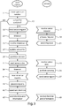
- Figure 3 is a flow chart that illustrates one example of cooperative sensing in accordance with an embodiment of the invention.
- the left side of figure 3 illustrates actions performed in a base station, which here act as an initiating node for the cooperative spectrum sensing.
- the right side of figure 3 illustrates actions performed in one exemplary sensor.
- the base station determines that more spectrum is needed in order to support the communication demand.
- the base station maintains a list of sensors that can be seen as candidates for participation in cooperative sensing.
- This list thus contains a candidate set of sensors.
- Such a candidate set is a subset of a "total set", that is, all nodes in some geographical area.
- a central node e.g. a base station in a cellular system or a master node in an ad hoc network
- the total set can be all nodes associated with that central node.
- the base station determines, at a block 13, whether the list is up to date. If the list is not up to date, the base station sends a sense request to all nodes associated the base station at a block 15. This sense request is then received by the sensors, illustrated by the exemplary sensor at a block 17. The exemplary sensor processes the sense request at a block 19 to determine whether it is currently a candidate for participation in cooperative spectrum sensing.
- the exemplary sensor is a candidate for cooperative spectrum sensing, and this is communicated to the base station in a response at a block 21.
- the base station receives this response, and possibly similar responses from other nodes, at a block 25.
- the base station updates the sensor list at a block 27.
- the base stations partitions the candidate set into two sets, one active set and one passive set.
- the active set contains the sensors that will participate in the cooperative sensing at this particular time
- the passive set contains the sensors in the candidate set that will not participate in the cooperative sensing at this particular time.
- the base station sends, at a block 31, a sense order that orders all sensors in the active set to perform sensing.
- a sense order that orders all sensors in the active set to perform sensing.
- the exemplary sensor is in the active set, and the exemplary sensor receives the sense order at a block 33.
- the exemplary sensor performs sensing at a block 35.
- the exemplary sensor sends a result of the sensing in a sense report to the base station at a block 37.
- the base station After a timeout (i.e., waiting period) 39, the base station receives this sense report, and similar sense reports from other sensors in the active set, at a block 41, and the received sense reports are then processed by the base station at a block 43. The processing of the sense reports results in a spectrum decision at a block 45.
- the spectrum decision establishes whether or not one or more spectrum opportunities have been detected as a result of the cooperative spectrum sensing.
- the base station transmits the spectrum decision and possibly additional information to relevant system nodes (e.g., nodes which are scheduled for transmission or reception in the detected spectrum opportunities). In this particular example, the exemplary node receives this transmission at a block 49.
- the partitioning of the candidate set into the active set and the passive set is allowed vary over time.
- the base station is responsible for partitioning the candidate set into the active set and the passive set, thereby in effect determining the sensors that should participate in the cooperative sensing.
- any apparatus not necessarily a base station, which has access to an element for sensor selection can be made responsible for this partitioning of the candidate set.
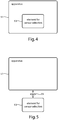
- Figure 4 is a schematic block diagram illustrating one example of such an apparatus 51.
- an element for sensor selection 53 is provided and contained in apparatus 51.
- a similar block diagram is shown in figure 5 .
- the element for sensor selection 53 and the apparatus 51 are physically distinct units that communicate through a communication channel 55.
- the element for sensor selection 53 can be implemented in various ways employing standard circuit technologies, such as application specific circuitry, programmable circuitry, or any combination thereof.
- the element 53 may also fully or partly be implemented with one or more processors programmed with suitable software.
- the element 53 for sensor selection can be implemented as a single unit, or it can be distributed over several units, e.g., several processors in a device, or several communicating devices.
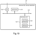
- Figure 10 is block diagram that illustrates a particular implementation embodiment of the element for sensor selection 53.
- the element for sensor selection 53 comprises a processor 151, a memory unit 153, and an input-output unit 155, which are all operationally connected, e.g. by means of a digital bus 157.
- the memory unit 153 stores a database 159 with information relevant the selection process.
- the database 159 includes information, which may initially have been received via the input-output unit 155, identifying the candidate set and other information relating to the candidate set, such as, for example, positioning information.
- the database 159 may also contain pre-stored data that can be used in the selection process, as will be exemplified below.
- the processor performs the selection process using software 161 and data that are provided by the memory unit 153 or via the input-output unit 155. As result of the selection process may be communicated via the input-output unit 155.
- the element for sensor selection 53 may in particular be configured to perform any one of the methods described and indicated below.
- the partitioning of the candidate set into the active set and the passive set is performed by solving an optimization problem.
- a cost formula is defined which describes how to calculate a cost for using a particular active set.
- the active set is then obtained by optimizing the cost in accordance with the cost formula, subject to suitable additional constraint(s), such as, for example, a desired number of sensors to be included in the active set.
- the cost measures c ij are fixed during the optimization procedure and may be viewed as components of a corresponding matrix C (the cost measure matrix).
- the formula (1) formally defines a numerical cost function on a power set P(S) of the candidate set S.
- the cost defined by the formula is an aggregate of "individual" costs and "pair-wise” costs.
- An individual cost is associated with each sensor which is a member of X and is given by a corresponding diagonal component of the cost measure matrix.
- a pair-wise cost is associated with each pair of distinct sensors that can be formed from members of X and is given by corresponding off-diagonal components of the cost measure matrix.
- the relationship between the cost measure matrix and the cost function is not one-to-one. That is, different cost measure matrices may result in the same cost function.
- Shadow fading arises from propagation loss behind large structures such as buildings and mountains.
- R(d) distance between two terminals
- the propagation environment can be characterized by a decorrelation distance, d 0 , which is a minimum separation between sensors required for a shadowing correlation to fall below a pre-determined threshold.
- the correlation threshold is a design parameter that may be selected depending on a maximal acceptable correlation between any two sensors that result in reliable results from the cooperative spectrum sensing.
- the decorrelation distance d 0 can be obtained from the equation (2) above for a given correlation threshold. In the following we will use the term "uncorrelated shadowing" for shadowing correlation below the threshold, i.e., when the separation of the two sensors is larger than d 0 .
- the cost measures will be based on shadowing correlation (correlation hereinafter).
- the cost measures will be referred to as correlation measures.
- the pair-wise correlation measures c ij (i not equal to j) may then be based on the above-described correlation function, R(d), where d is now and estimated Euclidian distance between sensors s(i) and s(j).
- the correlation measures should usually be based on a combination of a correlation function, the positions of sensor pairs and associated positioning uncertainty, and possibly additional parameters.
- correlation measures are two correlation measures which are important for the current application.
- the methodology presented herein can be used in other applications to maximize distance(s) between selected sensors, which is strictly speaking not a correlation measure, i.e., minimize -1 times the distance(s).
- a cell may be partitioned in a number of sectors which are large enough so that the correlation measures only have to be computed between all sensor pairs in the current and nearby sectors (for other sensor pairs, the correlation measure can be approximated to 0).
- the exemplary algorithms to be described can be straightforwardly implemented regardless on if the sensor positions are known in one dimension only (if, e.g., estimates of the distance of the sensors from a certain point (such as the main node, e.g., the BS) are known), in two dimensions (the estimated sensor positions are on a surface) or in three dimensions - it even generalizes up to any number of dimensions. In a good implementation of the algorithm, however, the correlation measure used will depend on the dimensionality of the position estimates.
- the user parameter N indicates the desired number of sensors to use in the cooperative sensing, i.e. the desired number of sensors in the active set.
- the passive set is of course the complement of A in S.
- the algorithm then iteratively removes sensors in a one-by-one fashion (always removing the sensor which has the largest summed correlation measure relative to the remaining sensors) until the desired number of sensors N has been obtained. Consequently, in each of the iterations, that sensor is removed, the removal of which results in the largest reduction in the cost, hence the name greedy approach.
- the algorithm can run in two modes.
- the appropriate mode should be selected based on the number of sensors available in the cell, on the processing power of the apparatus running the algorithm, and on how fast the solution needs to be obtained.
- Mode 1 can be used if the number of sensors available for sensing is lower than a pre-determined number K (K may be 0 or infinity, if one desires to always use one of the modes) . Otherwise, Mode 2 will be used.
- K may be 0 or infinity, if one desires to always use one of the modes.
- K may be 0 or infinity, if one desires to always use one of the modes
- Mode 2 will be used.
- Other criteria for selecting one of the two modes, or for combining them, are perfectly possible and are also covered by the invention.
- the active sensors are the same as the remaining elements. If the algorithm was run in Mode 2, the sensors are obtained by picking one sensor from each of the remaining elements. For elements which have more than one sensor associated with them, the selection can, e.g., be based on battery capacity of the sensors, sensing capabilities, or the sensor can be picked at random.
- the element k which maximizes the equation in point 2 is the element which has the greatest summed correlation measure to the remaining elements. Therefore, if the goal is to minimize the total correlation between the remaining sensors, element k should be removed.
- the algorithm never runs. Instead, the best-effort approach can be used, and all available sensors take part in the sensing.
- the starting point of the algorithm has a single active sensor (e.g., the sensor of a main node), and the other sensors passive.
- the passive sensors are then turned active in a one-by-one fashion, where the sensor to be activated is the passive sensor which has the minimum value of the summed correlation to the already active sensors.
- the stopping criteria used was that the number of remaining sensors reached a specified threshold. Also other stopping criteria are perfectly viable and covered by the invention. Such stopping criteria may be based, e.g., on the number of remaining sensors, the respective correlation of those, the mean correlation value of the remaining sensors, etc.
- the values of the summed correlation measures in point 2 above can be used as a basis for letting a stochastic variable decide which element to remove. Then, an element for which the corresponding summed correlation measure becomes large should have a larger chance of being removed.
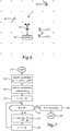
- Figure 7 is a flow chart that illustrates an implementation embodiment of the above-suggested optimization algorithm for selecting "elements" to the active set, but with a slight twist that avoids the cumbersome renumbering of the elements.
- a candidate set S including P elements e(1),...,e(P) is obtained at a block 73.
- the elements are sensors.
- the elements are active grid points.
- correlation measures relevant to the elements in question are obtained.
- An index set I is now introduced in order to avoid renumbering.
- the index set I is initially set to ⁇ 1,...,P ⁇ , reflecting a starting position for the greedy optimization procedure where all elements are initially assumed to be in an active set.
- an index value k associated with an element e(k) that is to be removed from the active set is calculated at a block 81.
- the element e(k) is the element currently in the active set which, when removed from the active set, causes the greatest cost reduction in accordance with the cost formula.
- the index set I is modified by removing the value k from the index set I.
- this operation is expressed compactly as a set difference between the index set I and a set ⁇ k ⁇ .
- the removal of the value k from the index set I is of course equivalent to removing the element e(k) from the active set.
- the active set A is finally established as including the elements for which the corresponding index values are still in the index set I.
- the optimization procedure of figure 7 ends at a block 87. If the number of elements in the candidate is less than the desired number N, then a best effort attempt is made by including all elements in the active set at the block 85.
- the elements (active grid points) must subsequently be translated into sensors, e.g. by picking, for each active grid point in the active set, a sensor that is associated with that grid point.
- the starting point was that all elements were in the active set (of elements), and element after element was then removed until the active set reached a suitable size N.
- the embodiment of figure 7 can easily be modified to account for this possibility. It is then convenient to introduce also a second index set J, which includes the index values of those elements that have not yet been selected to the active set. Consequently, with this approach, the index set I is initiated as the empty set and the index set J is initially set to ⁇ 1,...,P ⁇ , indicating that all elements are available for selection to the active set.
- the index set I may initially include a particular index value corresponding to some special element, e.g. a coordinating node, if such a node has sensor capabilities; this particular index value is then of course also removed form the index set J.
- the value k is then added to the set I and removed from the set J, indicating that element e(k) is now in the active set and that it cannot be selected again.
- the element e(k) is an element that causes a minimal increase in the cost when be added to the active set.
- the algorithm itself is not dependent on the use of a specific correlation measure. However, to illustrate what type of correlation measures can be used, and how to combine positioning uncertainty and correlation function, some examples of correlation measures are given below.
- the positions of the respective sensors are given with some uncertainty.
- the positions may be estimated by the sensors using the global positioning system (GPS) and reported to the coordinating node, or the estimation of positions is supported by the network, e.g., by letting the nodes listen to several nodes with known positions (such as BSs) and estimating the propagation delay, and thereby the distance, from those nodes.
- GPS global positioning system
- the position may be estimated.
- the positioning uncertainty is associated with the performance of the respective positioning algorithm, and is assumed to be known with some precision.
- the position uncertainty may also in certain cases be modelled as a normal distribution, centred at an estimated expected position of a sensor and with a standard deviation that represents the uncertainty in the positioning system used.
- the correlation function which can be different for different types of environment (urban, suburban, etc), is generally a function of the (scalar) distance d between two locations: R(d).
- p m d ij ⁇ R ⁇ d ij ⁇
- d ij 2-D Gaussian distributed and if the norm ⁇ is the Euclidian norm, one can show that ⁇ d ij ⁇ has a Ricean distribution. If the algorithm above runs in Mode 2, the above equation can be computed offline for all pairs of grid points.
- R(d) can be a function which does not directly describe the correlation, but rather gives a notion of how the sensing performance is hurt by sensor distance.
- R(d) can be much larger and more slowly decaying within the decorrelation distance d 0 than what is suggested by the exponential decay.
- the correlation function R(d) could be used directly as a correlation measure, where d is set to the distance vector norm between the two locations (thereby, ignoring the positioning uncertainty, which is small anyway in this case).
- Another option is to convolve the correlation function with two 1-D functions describing the positioning uncertainty of the two locations, respectively, and then use the resulting 1-D function as correlation measure, again giving the norm distance between the location mean values as input.
- the correlation measures of the form c ii were all assumed equal. As is well understood by a person skilled in the art, these correlation measures will then not influence the optimization procedure that determines the active and passive sets. However, it is not necessary to make this assumption. Note that the value c ii can be used to describe the attractiveness of using sensor number i as compared to the other sensors. For example, sensor number i may be known to have larger battery and better sensing performance than sensor number j, then one could set c ii ⁇ c jj .
- a main node has very good sensing capabilities (e.g., the main node is a BS in a cellular system)
- the corresponding c ii value could be set very low, even to minus infinity, to guarantee that this sensor will be used in the sensing.
- the same could also apply to fixed sensors, for example, at repeaters owned by the sensing system.
- This algorithm iteratively partitions the sensors into the two subsets; the active set and the passive set.
- the inputs to this algorithm are the estimates of the positions of the sensors that are available for sensing, and the decorrelation distance d 0 .
- the algorithm starts with the active set containing only the main node (e.g., the base station in a cellular system).
- the main node in the example implementation of the invention has spectrum sensing abilities. This not being the case is not a limitation of the invention - instead an arbitrary node can be used as starting sensor.
- the algorithm investigates, sensor by sensor, whether or not the individual sensors are at positions further away from all the present sensors in the active set than the decorrelation distance d 0 (possibly, also an extra margin for positioning uncertainty can be added). If this is the case for a sensor it is added to the active set and if this is not the case for the sensor it is added to the passive set.
- This procedure iteratively increases the size of the active set until we have reached a predefined target number N of sensors to participate in the cooperative sensing activity, or until all sensor positions have been investigated and no further sensors are available for consideration (best effort).
- a target value for the maximum number of sensors that are allowed to participate in the sensing may or may not exist.
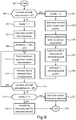
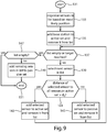
- FIG. 9 is flow chart that illustrates an implementation embodiment of this approach to sensor selection. After a start 131, sensors in a candidate set are organised in a list based on their estimated positions at a block 133. The sensors may, for example, be sorted by increasing distance to the base station. At a block 135, the base station is added to the active set and then removed from the list. At a block 137, it is checked whether the list is empty or if the target number N of active sensors has been reached.
- the method proceeds to a block 139, where a next sensor is selected from the list. It is then checked, at a block 141, whether the selected sensor has distance to each sensor in the active set that greater than the decorrelation distance d 0 , or, alternatively, greater than the decorrelation distance d 0 plus an extra margin ⁇ . If this is the case, the selected sensor is added to the active set and is then removed from the list at block 143. Otherwise, the selected sensor is added to the passive set and is then removed from the list at a block 145. Once the selected sensor has been removed from the list, the method returns the block 137, and the method thus proceed as described until at least one of the conditions is met at the block 137.
- the method continues, at a block 147, by checking whether the list is empty or not. If the list is empty, the method ends at a block 151. Otherwise, any remaining sensor in the list is added the passive set at a block 149 before the method ends at the block 151.
- the embodiment illustrated in figure 9 is not unrelated to previous embodiments.
- the method of figure 9 may therefore, as an alternative, be run as a cost optimization using any one of the optimization procedures described and indicated above and using correlation measures of the above-indicated form, and this alternative is also included herein as an embodiment of the invention.
- the methods described above have been evaluated in simulations, considering both the pair-wise correlations between the selected sensors, according to a correlation model, and the actual detection performance of the selected sensors, using energy detection and a K-out-of-N detector (i.e., if K or more of the N used sensors detect primary usage, then the system decides that primary use is taking place, otherwise the system decides that no primary user is active).
- the conclusion from the evaluation is that the pair-wise correlations between the selected sensors becomes lower than when the same number of sensors are selected at random.
- the sensing performance is improved when using sensors selected by the algorithms described above as opposed to random selection of the same amount of sensors. This in terms of improved probability of primary user detection and/or reduced probability of false alarm (i.e., reaching a false decision that a primary user is active, leading to a missed spectrum opportunity).
Landscapes
- Engineering & Computer Science (AREA)
- Computer Networks & Wireless Communication (AREA)
- Signal Processing (AREA)
- Mobile Radio Communication Systems (AREA)
- Monitoring And Testing Of Transmission In General (AREA)
Claims (11)
- Procédé relatif à la détection coopérative de spectre, le procédé comprenant les étapes suivantes réalisées par un élément (53) de sélection de capteurs :l'obtention (73) d'un ensemble candidat de capteurs (67.1) qui sont disponibles pour participer à la détection coopérative de spectre ;la définition (75) d'une formule de coûts pour calculer un coût associé à l'utilisation de capteurs parmi l'ensemble candidat dans la détection coopérative de spectre ; etle partitionnement (29) de l'ensemble candidat en un ensemble actif contenant un ou plusieurs capteurs quelconques parmi l'ensemble candidat destinés à participer à la détection coopérative de spectre et un ensemble passif contenant un ou plusieurs capteurs quelconques parmi l'ensemble candidat qui ne sont pas destinés à participer à la détection coopérative de spectre par l'application d'une procédure d'optimisation (79, 81, 83 ; 111, 113, 115) qui effectue une optimisation sous contraintes du coût en fonction de la formule de coûts définie,dans laquelle il existe M capteurs parmi l'ensemble candidat qui sont numérotés de 1 à M, et la formule de coûts étant

- Procédé selon la revendication 1, dans lequel les valeurs Cij, i,j=1,..,M, représentent des mesures de corrélation fictive entre le capteur numéro i et le capteur numéro j.
- Procédé selon la revendication 2, dans lequel les mesures de corrélation fictive sont basées au moins en partie sur une fonction de corrélation modélisant la corrélation fictive en fonction d'au moins une distance entre capteurs.
- Procédé selon la revendication 3, dans lequel les mesures de corrélation fictive sont en outre basées au moins en partie sur des incertitudes de positionnement des capteurs parmi l'ensemble candidat.
- Procédé selon la revendication 4, dans lequel les mesures de corrélation fictive sont obtenues par le calcul d'une valeur attendue de la fonction de corrélation conditionnée sur une distribution des probabilités de distances vectorielles entre capteurs.
- Procédé selon la revendication 1, le procédé comprenant en outre la détermination de l'opportunité de réaliser le procédé dans un premier mode ou un second mode, le second mode étant moins intensif du point de vue des calculs que le premier mode.
- Procédé selon la revendication 6, dans lequel le premier mode comprend la définition de la formule de coûts comme

- Procédé selon l'une quelconque des revendications 6 ou 7, dans lequel le second mode comprend :l'association (103) de chaque capteur parmi l'ensemble candidat à un point de grille le plus proche parmi un ensemble prédéfini de points de grille (65) ;l'élimination (105) de l'étude de tout point de grille prédéfini auquel n'est associé aucun capteur ;la définition (107) de la formule de coûts comme
 la traduction (121) de l'ensemble actif de points de grille en ensemble actif de capteurs à utiliser dans la détection coopérative de spectre.
 - Procédé selon l'une quelconque des revendications 1 à 8, dans lequel la procédure d'optimisation est une approche d'optimisation glouton.
- Procédé selon l'une quelconque des revendications 1 à 9, dans lequel la procédure d'optimisation est sujette à une contrainte (115) spécifiant un nombre de capteurs qui devraient faire partie de l'ensemble actif.
- Élément (53) de sélection de capteurs, l'élément comprenant des moyens permettant de réaliser les étapes d'un procédé selon l'une quelconque des revendications précitées.
Applications Claiming Priority (2)
| Application Number | Priority Date | Filing Date | Title |
|---|---|---|---|
| US5866808P | 2008-06-04 | 2008-06-04 | |
| PCT/SE2009/050660 WO2009148399A1 (fr) | 2008-06-04 | 2009-06-03 | Procédé et appareil relatifs à la détection de spectre |
Publications (3)
| Publication Number | Publication Date |
|---|---|
| EP2283671A1 EP2283671A1 (fr) | 2011-02-16 |
| EP2283671A4 EP2283671A4 (fr) | 2017-06-28 |
| EP2283671B1 true EP2283671B1 (fr) | 2019-08-07 |
Family
ID=41398330
Family Applications (3)
| Application Number | Title | Priority Date | Filing Date |
|---|---|---|---|
| EP09758620.0A Active EP2283685B1 (fr) | 2008-06-04 | 2009-06-01 | Procédé et appareil relatifs à la détection du spectre |
| EP09758626.7A Active EP2283671B1 (fr) | 2008-06-04 | 2009-06-03 | Procédé et appareil relatifs à la détection de spectre |
| EP09758628.3A Withdrawn EP2283672A4 (fr) | 2008-06-04 | 2009-06-04 | Procédé et appareil associés à la détection de spectre |
Family Applications Before (1)
| Application Number | Title | Priority Date | Filing Date |
|---|---|---|---|
| EP09758620.0A Active EP2283685B1 (fr) | 2008-06-04 | 2009-06-01 | Procédé et appareil relatifs à la détection du spectre |
Family Applications After (1)
| Application Number | Title | Priority Date | Filing Date |
|---|---|---|---|
| EP09758628.3A Withdrawn EP2283672A4 (fr) | 2008-06-04 | 2009-06-04 | Procédé et appareil associés à la détection de spectre |
Country Status (8)
| Country | Link |
|---|---|
| US (3) | US8509701B2 (fr) |
| EP (3) | EP2283685B1 (fr) |
| JP (1) | JP5337873B2 (fr) |
| CN (2) | CN102057736B (fr) |
| ES (1) | ES2751718T3 (fr) |
| HU (1) | HUE047383T2 (fr) |
| PL (1) | PL2283685T3 (fr) |
| WO (3) | WO2009148393A1 (fr) |
Families Citing this family (34)
| Publication number | Priority date | Publication date | Assignee | Title |
|---|---|---|---|---|
| US8971441B2 (en) * | 2009-06-08 | 2015-03-03 | Lawrence Livermore National Security, Llc | Transmit-reference methods in software defined radio platforms for communication in harsh propagation environments and systems thereof |
| US8160004B2 (en) * | 2009-06-30 | 2012-04-17 | Motorola Solutions, Inc. | Method for optimizing spatial diversity gain of a set of nodes used for cooperative sensing |
| US9516686B2 (en) * | 2010-03-17 | 2016-12-06 | Qualcomm Incorporated | Method and apparatus for establishing and maintaining peer-to-peer (P2P) communication on unlicensed spectrum |
| US8548465B2 (en) * | 2010-04-23 | 2013-10-01 | Apple Inc. | Methods and apparatus for providing dynamic information in a wireless information channel |
| US8478319B2 (en) * | 2010-05-12 | 2013-07-02 | Information System Technologies, Inc. | Feature extraction and data compression system and method for distributed sensor networks |
| CN102271021B (zh) * | 2010-06-02 | 2014-09-03 | 华为技术有限公司 | 协同频谱感知方法、基站和终端 |
| US8380234B2 (en) * | 2010-09-14 | 2013-02-19 | Telefonaktiebolaget Lm Ericsson (Publ) | Method and apparatus for transmitting available radio access possibilities in a communications area |
| US20120083218A1 (en) * | 2010-09-30 | 2012-04-05 | Hrishikesh Gossain | System and method for collaborative spectrum analysis |
| CN103299590B (zh) | 2010-10-11 | 2017-04-05 | 交互数字专利控股公司 | 用于为认知无线电网络的带宽分配的方法和装置 |
| US20120134328A1 (en) * | 2010-10-11 | 2012-05-31 | Interdigital Patent Holdings, Inc. | Method and apparatus for dynamic spectrum management |
| US9807778B2 (en) | 2010-10-11 | 2017-10-31 | Interdigital Patent Holdings, Inc. | Dynamic spectrum management |
| WO2012068731A1 (fr) * | 2010-11-25 | 2012-05-31 | Nokia Corporation | Détection assistée par réseau sur une bande partagée pour des communications locales |
| US8774111B2 (en) * | 2011-05-06 | 2014-07-08 | Dynamic Invention Llc | Fair and efficient channel allocation and spectrum sensing for cognitive OFDMA networks |
| CN102223191B (zh) * | 2011-06-02 | 2014-11-05 | 电信科学技术研究院 | 一种空闲频谱的获取方法和设备 |
| CN103052095B (zh) * | 2011-10-11 | 2015-10-14 | 中国普天信息产业股份有限公司 | 频谱检测方法和系统 |
| CN103428712B (zh) | 2012-05-16 | 2016-08-10 | 华为技术有限公司 | 一种侦听方法和节点 |
| CN103428706B (zh) * | 2012-05-17 | 2016-09-21 | 普天信息技术研究院有限公司 | 协作频谱感知节点的选择方法 |
| US9544777B2 (en) | 2012-06-18 | 2017-01-10 | Microsoft Technology Licensing, Llc | White space utilization |
| US9288681B2 (en) | 2012-06-18 | 2016-03-15 | Microsoft Technology Licensing, Llc | White space utilization |
| WO2014003358A1 (fr) * | 2012-06-24 | 2014-01-03 | 엘지전자 주식회사 | Procédé et dispositif pour réaliser une communication directe entre des terminaux dans un système de communication sans fil |
| US9094834B2 (en) | 2012-09-11 | 2015-07-28 | Microsoft Technology Licensing, Llc | White space utilization |
| US9288682B2 (en) | 2013-02-22 | 2016-03-15 | Microsoft Technology Licensing, Llc | White space utilization |
| US9854501B2 (en) | 2013-03-14 | 2017-12-26 | Microsoft Technology Licensing, Llc | Radio spectrum utilization |
| EP2824589A1 (fr) * | 2013-07-12 | 2015-01-14 | Thomson Licensing | Procédé pour enrichir un contenu multimédia et dispositif correspondant |
| CN103746754B (zh) * | 2013-12-27 | 2016-01-20 | 中国电子科技集团公司第二十八研究所 | 基于概率统计的检测可靠性估计方法 |
| CN104702355B (zh) * | 2015-02-26 | 2017-04-26 | 西安电子科技大学 | 一种大小尺度衰落信道下宽带协作频谱感知方法 |
| US20160345165A1 (en) * | 2015-05-22 | 2016-11-24 | Qualcomm Incorporated | Collecting data from a statistically significant group of mobile devices |
| CN105207728B (zh) * | 2015-09-02 | 2018-02-16 | 哈尔滨工业大学 | 基于中继的分布式协作频谱感知的方法 |
| WO2017128045A1 (fr) * | 2016-01-26 | 2017-08-03 | Telefonaktiebolaget Lm Ericsson (Publ) | Procédé et appareil de transmission de données |
| CN106230530B (zh) * | 2016-09-23 | 2018-08-31 | 宁波大学 | 多频段协作认知频谱感知方法 |
| CN106411429B (zh) * | 2016-09-23 | 2018-11-23 | 宁波大学 | 多信道认知无线网络信号辨识方法 |
| CN108024264B (zh) * | 2016-11-03 | 2022-08-02 | 中兴通讯股份有限公司 | 一种资源选择方法及装置 |
| WO2020223977A1 (fr) * | 2019-05-09 | 2020-11-12 | 北京小米移动软件有限公司 | Procédé et appareil de commande d'accès, et support de stockage lisible |
| WO2023155149A1 (fr) * | 2022-02-18 | 2023-08-24 | Oppo广东移动通信有限公司 | Procédé et dispositif de communication sans fil |
Family Cites Families (23)
| Publication number | Priority date | Publication date | Assignee | Title |
|---|---|---|---|---|
| US6611500B1 (en) | 1999-11-04 | 2003-08-26 | Lucent Technologies, Inc. | Methods and apparatus for derivative-based optimization of wireless network performance |
| US7184777B2 (en) * | 2002-11-27 | 2007-02-27 | Cognio, Inc. | Server and multiple sensor system for monitoring activity in a shared radio frequency band |
| US7526255B2 (en) * | 2005-04-05 | 2009-04-28 | Cisco Technology, Inc. | Method and system for coordinating radio resources in unlicensed frequency bands |
| US20070032254A1 (en) * | 2005-08-02 | 2007-02-08 | Hitachi, Ltd. | System and method for providing efficient spectrum usage of wireless devices in unlicensed bands |
| KR100785799B1 (ko) * | 2005-10-14 | 2007-12-13 | 한국전자통신연구원 | 다중 주파수채널 시스템에서 효율적인 스펙트럼 센싱을이용한 채널 할당 방법 |
| EP1977563B1 (fr) * | 2006-01-11 | 2018-01-03 | QUALCOMM Incorporated | Codage de signaux de balise pour l'identification dans une communication de pair a pair |
| CN100574139C (zh) | 2006-06-30 | 2009-12-23 | 西安电子科技大学 | 认知无线电中频谱空洞的探测方法 |
| CN100459807C (zh) * | 2006-07-24 | 2009-02-04 | 西南交通大学 | 用于无线通信的次用户协作、周期稳态特征检测主用户频谱洞的方法 |
| WO2008016944A2 (fr) * | 2006-07-31 | 2008-02-07 | Qualcomm Incorporated | Détermination de paramètres rf cellulaires sur la base de mesures par des équipements utilisateurs |
| US7860197B2 (en) * | 2006-09-29 | 2010-12-28 | Samsung Electro-Mechanics | Spectrum-sensing algorithms and methods |
| US8655283B2 (en) * | 2007-04-23 | 2014-02-18 | Lingna Holdings Pte., Llc | Cluster-based cooperative spectrum sensing in cognitive radio systems |
| US8041380B2 (en) * | 2007-04-26 | 2011-10-18 | Lingna Holdings Pte., Llc | Power control in cognitive radio systems based on spectrum sensing side information |
| US7813739B2 (en) * | 2007-09-27 | 2010-10-12 | Koon Hoo Teo | Method for reducing inter-cell interference in wireless OFDMA networks |
| JP5333940B2 (ja) * | 2007-12-28 | 2013-11-06 | 日本電気株式会社 | 無線機、無線通信システムおよび無線電波の検出方法 |
| EP2237588B1 (fr) * | 2007-12-28 | 2019-08-21 | NEC Corporation | Système de communication sans fil, procédé de communication sans fil et dispositif sans fil |
| US8428632B2 (en) * | 2008-03-31 | 2013-04-23 | Motorola Solutions, Inc. | Dynamic allocation of spectrum sensing resources in cognitive radio networks |
| GB2464289B (en) * | 2008-10-08 | 2012-12-05 | Samsung Electronics Co Ltd | Estimating link qualities in multi-carrier systems |
| US8175594B2 (en) * | 2008-10-24 | 2012-05-08 | Qualcomm Incorporated | Active set management with hotspot carriers |
| US8472868B2 (en) * | 2009-05-06 | 2013-06-25 | Telefonaktiebolaget Lm Ericsson (Publ) | Method and apparatus for MIMO repeater chains in a wireless communication network |
| US8582481B2 (en) * | 2010-01-21 | 2013-11-12 | Ajou University Industry-Academic Cooperation Foundation | LoWMob and DLoWMob system |
| US8775065B2 (en) * | 2010-04-05 | 2014-07-08 | Qualcomm Incorporated | Radio model updating |
| EP2453711B1 (fr) * | 2010-11-15 | 2015-06-03 | NTT DoCoMo, Inc. | Procédé pour attribuer des sous-bandes de fréquence à une pluralité de noeuds interférant dans un réseau de communication sans fil, contrôleur pour un réseau de communication sans fil et réseau de communication sans fil |
| US8849217B2 (en) * | 2011-06-22 | 2014-09-30 | Broadcom Corporation | Antenna arrangement |
-
2009
- 2009-06-01 CN CN200980120698.8A patent/CN102057736B/zh not_active Expired - Fee Related
- 2009-06-01 US US12/990,880 patent/US8509701B2/en not_active Expired - Fee Related
- 2009-06-01 PL PL09758620T patent/PL2283685T3/pl unknown
- 2009-06-01 HU HUE09758620A patent/HUE047383T2/hu unknown
- 2009-06-01 EP EP09758620.0A patent/EP2283685B1/fr active Active
- 2009-06-01 ES ES09758620T patent/ES2751718T3/es active Active
- 2009-06-01 WO PCT/SE2009/050634 patent/WO2009148393A1/fr not_active Ceased
- 2009-06-03 WO PCT/SE2009/050660 patent/WO2009148399A1/fr not_active Ceased
- 2009-06-03 EP EP09758626.7A patent/EP2283671B1/fr active Active
- 2009-06-03 US US12/994,207 patent/US8995922B2/en not_active Expired - Fee Related
- 2009-06-03 CN CN2009801207942A patent/CN102057711B/zh not_active Expired - Fee Related
- 2009-06-04 US US12/993,555 patent/US8270906B2/en not_active Expired - Fee Related
- 2009-06-04 WO PCT/SE2009/050673 patent/WO2009148401A1/fr not_active Ceased
- 2009-06-04 JP JP2011512415A patent/JP5337873B2/ja not_active Expired - Fee Related
- 2009-06-04 EP EP09758628.3A patent/EP2283672A4/fr not_active Withdrawn
Non-Patent Citations (1)
| Title |
|---|
| None * |
Also Published As
| Publication number | Publication date |
|---|---|
| HUE047383T2 (hu) | 2020-04-28 |
| US8270906B2 (en) | 2012-09-18 |
| WO2009148399A1 (fr) | 2009-12-10 |
| JP5337873B2 (ja) | 2013-11-06 |
| EP2283671A1 (fr) | 2011-02-16 |
| US20110065471A1 (en) | 2011-03-17 |
| PL2283685T3 (pl) | 2020-03-31 |
| EP2283685B1 (fr) | 2019-08-07 |
| EP2283685A1 (fr) | 2011-02-16 |
| EP2283685A4 (fr) | 2017-03-22 |
| US8509701B2 (en) | 2013-08-13 |
| EP2283671A4 (fr) | 2017-06-28 |
| ES2751718T3 (es) | 2020-04-01 |
| US20110076959A1 (en) | 2011-03-31 |
| US20110098005A1 (en) | 2011-04-28 |
| CN102057736B (zh) | 2014-04-09 |
| EP2283672A4 (fr) | 2017-03-22 |
| CN102057711B (zh) | 2013-09-25 |
| CN102057711A (zh) | 2011-05-11 |
| JP2011524126A (ja) | 2011-08-25 |
| EP2283672A1 (fr) | 2011-02-16 |
| WO2009148393A1 (fr) | 2009-12-10 |
| WO2009148401A1 (fr) | 2009-12-10 |
| CN102057736A (zh) | 2011-05-11 |
| US8995922B2 (en) | 2015-03-31 |
Similar Documents
| Publication | Publication Date | Title |
|---|---|---|
| EP2283671B1 (fr) | Procédé et appareil relatifs à la détection de spectre | |
| Rawat et al. | Dynamic spectrum access for wireless networks | |
| US8787922B2 (en) | System and method for cooperative inter-cell interference control | |
| Abozariba et al. | NOMA-based resource allocation and mobility enhancement framework for IoT in next generation cellular networks | |
| Debroy et al. | Contention based multichannel MAC protocol for distributed cognitive radio networks | |
| CN102377494B (zh) | 频谱感知方法、装置及系统 | |
| Nguyen et al. | A stochastic geometry model for cognitive radio networks | |
| Alsarhan et al. | Optimal spectrum utilisation in cognitive network using combined spectrum sharing approach: overlay, underlay and trading | |
| Shokri-Ghadikolaei et al. | Distributed multiuser sequential channel sensing schemes in multichannel cognitive radio networks | |
| Nguyen et al. | Effective scheduling in infrastructure-based cognitive radio networks | |
| Xin et al. | ROP: Near-optimal rendezvous for dynamic spectrum access networks | |
| Na et al. | Reinforcement-learning-based spatial resource identification for IoT D2D communications | |
| Afsana et al. | Trust and energy aware Cluster modeling and spectrum handoff for cognitive radio ad-hoc network | |
| Sardar et al. | Sustainability analysis of opportunistic CR-IoT network employing microwave power transfer | |
| Khalvandi et al. | Numerical evaluation of distributed wireless networks at scale | |
| Yan et al. | Performance analysis of secondary users in dynamic spectrum access under interference temperature constraints | |
| Biswas et al. | Optimal resource allocation in a price based opportunistic cognitive radio network | |
| Sarigiannidis et al. | Adaptive sensing policies for cognitive wireless networks using learning automata | |
| Chen et al. | On the performance of delay aware shared access with priorities | |
| KR101682290B1 (ko) | 다중셀 랜덤엑세스 네트워크에서 간섭정렬 및 제어를 위한 프레임 전송 시스템 및 방법 | |
| Hoang | 10 Cognitive Radio Networks with Wireless Energy Harvesting | |
| Sharma | Resource management in location aware cognitive radio networks | |
| Ullah | Mechanisms for Enhancing Spectrum Utilization in a Spectrum Access System | |
| Sodagari | Mechanisms for Increasing Efficiency and Security of Cognitive Radio Using Incentive Alleviation and Design of Experiments | |
| Salameh | Channel access mechanisms and protocols for opportunistic cognitive radio networks |
Legal Events
| Date | Code | Title | Description |
|---|---|---|---|
| PUAI | Public reference made under article 153(3) epc to a published international application that has entered the european phase |
Free format text: ORIGINAL CODE: 0009012 |
|
| 17P | Request for examination filed |
Effective date: 20101102 |
|
| AK | Designated contracting states |
Kind code of ref document: A1 Designated state(s): AT BE BG CH CY CZ DE DK EE ES FI FR GB GR HR HU IE IS IT LI LT LU LV MC MK MT NL NO PL PT RO SE SI SK TR |
|
| AX | Request for extension of the european patent |
Extension state: AL BA RS |
|
| DAX | Request for extension of the european patent (deleted) | ||
| RIC1 | Information provided on ipc code assigned before grant |
Ipc: H04W 24/08 20090101AFI20170214BHEP |
|
| REG | Reference to a national code |
Ref country code: DE Ref legal event code: R079 Ref document number: 602009059370 Country of ref document: DE Free format text: PREVIOUS MAIN CLASS: H04W0016140000 Ipc: H04W0024080000 |
|
| STAA | Information on the status of an ep patent application or granted ep patent |
Free format text: STATUS: EXAMINATION IS IN PROGRESS |
|
| RA4 | Supplementary search report drawn up and despatched (corrected) |
Effective date: 20170526 |
|
| RIC1 | Information provided on ipc code assigned before grant |
Ipc: H04W 24/08 20090101AFI20170519BHEP |
|
| 17Q | First examination report despatched |
Effective date: 20170619 |
|
| GRAP | Despatch of communication of intention to grant a patent |
Free format text: ORIGINAL CODE: EPIDOSNIGR1 |
|
| STAA | Information on the status of an ep patent application or granted ep patent |
Free format text: STATUS: GRANT OF PATENT IS INTENDED |
|
| INTG | Intention to grant announced |
Effective date: 20190329 |
|
| GRAS | Grant fee paid |
Free format text: ORIGINAL CODE: EPIDOSNIGR3 |
|
| GRAA | (expected) grant |
Free format text: ORIGINAL CODE: 0009210 |
|
| STAA | Information on the status of an ep patent application or granted ep patent |
Free format text: STATUS: THE PATENT HAS BEEN GRANTED |
|
| AK | Designated contracting states |
Kind code of ref document: B1 Designated state(s): AT BE BG CH CY CZ DE DK EE ES FI FR GB GR HR HU IE IS IT LI LT LU LV MC MK MT NL NO PL PT RO SE SI SK TR |
|
| REG | Reference to a national code |
Ref country code: GB Ref legal event code: FG4D |
|
| REG | Reference to a national code |
Ref country code: CH Ref legal event code: EP Ref country code: AT Ref legal event code: REF Ref document number: 1165759 Country of ref document: AT Kind code of ref document: T Effective date: 20190815 |
|
| REG | Reference to a national code |
Ref country code: DE Ref legal event code: R096 Ref document number: 602009059370 Country of ref document: DE |
|
| REG | Reference to a national code |
Ref country code: IE Ref legal event code: FG4D |
|
| REG | Reference to a national code |
Ref country code: NL Ref legal event code: MP Effective date: 20190807 |
|
| REG | Reference to a national code |
Ref country code: LT Ref legal event code: MG4D |
|
| PG25 | Lapsed in a contracting state [announced via postgrant information from national office to epo] |
Ref country code: NO Free format text: LAPSE BECAUSE OF FAILURE TO SUBMIT A TRANSLATION OF THE DESCRIPTION OR TO PAY THE FEE WITHIN THE PRESCRIBED TIME-LIMIT Effective date: 20191107 Ref country code: FI Free format text: LAPSE BECAUSE OF FAILURE TO SUBMIT A TRANSLATION OF THE DESCRIPTION OR TO PAY THE FEE WITHIN THE PRESCRIBED TIME-LIMIT Effective date: 20190807 Ref country code: LT Free format text: LAPSE BECAUSE OF FAILURE TO SUBMIT A TRANSLATION OF THE DESCRIPTION OR TO PAY THE FEE WITHIN THE PRESCRIBED TIME-LIMIT Effective date: 20190807 Ref country code: SE Free format text: LAPSE BECAUSE OF FAILURE TO SUBMIT A TRANSLATION OF THE DESCRIPTION OR TO PAY THE FEE WITHIN THE PRESCRIBED TIME-LIMIT Effective date: 20190807 Ref country code: BG Free format text: LAPSE BECAUSE OF FAILURE TO SUBMIT A TRANSLATION OF THE DESCRIPTION OR TO PAY THE FEE WITHIN THE PRESCRIBED TIME-LIMIT Effective date: 20191107 Ref country code: NL Free format text: LAPSE BECAUSE OF FAILURE TO SUBMIT A TRANSLATION OF THE DESCRIPTION OR TO PAY THE FEE WITHIN THE PRESCRIBED TIME-LIMIT Effective date: 20190807 Ref country code: HR Free format text: LAPSE BECAUSE OF FAILURE TO SUBMIT A TRANSLATION OF THE DESCRIPTION OR TO PAY THE FEE WITHIN THE PRESCRIBED TIME-LIMIT Effective date: 20190807 Ref country code: PT Free format text: LAPSE BECAUSE OF FAILURE TO SUBMIT A TRANSLATION OF THE DESCRIPTION OR TO PAY THE FEE WITHIN THE PRESCRIBED TIME-LIMIT Effective date: 20191209 |
|
| REG | Reference to a national code |
Ref country code: AT Ref legal event code: MK05 Ref document number: 1165759 Country of ref document: AT Kind code of ref document: T Effective date: 20190807 |
|
| PG25 | Lapsed in a contracting state [announced via postgrant information from national office to epo] |
Ref country code: GR Free format text: LAPSE BECAUSE OF FAILURE TO SUBMIT A TRANSLATION OF THE DESCRIPTION OR TO PAY THE FEE WITHIN THE PRESCRIBED TIME-LIMIT Effective date: 20191108 Ref country code: IS Free format text: LAPSE BECAUSE OF FAILURE TO SUBMIT A TRANSLATION OF THE DESCRIPTION OR TO PAY THE FEE WITHIN THE PRESCRIBED TIME-LIMIT Effective date: 20191207 Ref country code: LV Free format text: LAPSE BECAUSE OF FAILURE TO SUBMIT A TRANSLATION OF THE DESCRIPTION OR TO PAY THE FEE WITHIN THE PRESCRIBED TIME-LIMIT Effective date: 20190807 Ref country code: ES Free format text: LAPSE BECAUSE OF FAILURE TO SUBMIT A TRANSLATION OF THE DESCRIPTION OR TO PAY THE FEE WITHIN THE PRESCRIBED TIME-LIMIT Effective date: 20190807 |
|
| PG25 | Lapsed in a contracting state [announced via postgrant information from national office to epo] |
Ref country code: TR Free format text: LAPSE BECAUSE OF FAILURE TO SUBMIT A TRANSLATION OF THE DESCRIPTION OR TO PAY THE FEE WITHIN THE PRESCRIBED TIME-LIMIT Effective date: 20190807 |
|
| PG25 | Lapsed in a contracting state [announced via postgrant information from national office to epo] |
Ref country code: IT Free format text: LAPSE BECAUSE OF FAILURE TO SUBMIT A TRANSLATION OF THE DESCRIPTION OR TO PAY THE FEE WITHIN THE PRESCRIBED TIME-LIMIT Effective date: 20190807 Ref country code: RO Free format text: LAPSE BECAUSE OF FAILURE TO SUBMIT A TRANSLATION OF THE DESCRIPTION OR TO PAY THE FEE WITHIN THE PRESCRIBED TIME-LIMIT Effective date: 20190807 Ref country code: AT Free format text: LAPSE BECAUSE OF FAILURE TO SUBMIT A TRANSLATION OF THE DESCRIPTION OR TO PAY THE FEE WITHIN THE PRESCRIBED TIME-LIMIT Effective date: 20190807 Ref country code: PL Free format text: LAPSE BECAUSE OF FAILURE TO SUBMIT A TRANSLATION OF THE DESCRIPTION OR TO PAY THE FEE WITHIN THE PRESCRIBED TIME-LIMIT Effective date: 20190807 Ref country code: DK Free format text: LAPSE BECAUSE OF FAILURE TO SUBMIT A TRANSLATION OF THE DESCRIPTION OR TO PAY THE FEE WITHIN THE PRESCRIBED TIME-LIMIT Effective date: 20190807 Ref country code: EE Free format text: LAPSE BECAUSE OF FAILURE TO SUBMIT A TRANSLATION OF THE DESCRIPTION OR TO PAY THE FEE WITHIN THE PRESCRIBED TIME-LIMIT Effective date: 20190807 |
|
| PG25 | Lapsed in a contracting state [announced via postgrant information from national office to epo] |
Ref country code: CZ Free format text: LAPSE BECAUSE OF FAILURE TO SUBMIT A TRANSLATION OF THE DESCRIPTION OR TO PAY THE FEE WITHIN THE PRESCRIBED TIME-LIMIT Effective date: 20190807 Ref country code: IS Free format text: LAPSE BECAUSE OF FAILURE TO SUBMIT A TRANSLATION OF THE DESCRIPTION OR TO PAY THE FEE WITHIN THE PRESCRIBED TIME-LIMIT Effective date: 20200224 Ref country code: SK Free format text: LAPSE BECAUSE OF FAILURE TO SUBMIT A TRANSLATION OF THE DESCRIPTION OR TO PAY THE FEE WITHIN THE PRESCRIBED TIME-LIMIT Effective date: 20190807 |
|
| REG | Reference to a national code |
Ref country code: DE Ref legal event code: R097 Ref document number: 602009059370 Country of ref document: DE |
|
| PLBE | No opposition filed within time limit |
Free format text: ORIGINAL CODE: 0009261 |
|
| STAA | Information on the status of an ep patent application or granted ep patent |
Free format text: STATUS: NO OPPOSITION FILED WITHIN TIME LIMIT |
|
| PG2D | Information on lapse in contracting state deleted |
Ref country code: IS |
|
| 26N | No opposition filed |
Effective date: 20200603 |
|
| PG25 | Lapsed in a contracting state [announced via postgrant information from national office to epo] |
Ref country code: SI Free format text: LAPSE BECAUSE OF FAILURE TO SUBMIT A TRANSLATION OF THE DESCRIPTION OR TO PAY THE FEE WITHIN THE PRESCRIBED TIME-LIMIT Effective date: 20190807 |
|
| PG25 | Lapsed in a contracting state [announced via postgrant information from national office to epo] |
Ref country code: MC Free format text: LAPSE BECAUSE OF FAILURE TO SUBMIT A TRANSLATION OF THE DESCRIPTION OR TO PAY THE FEE WITHIN THE PRESCRIBED TIME-LIMIT Effective date: 20190807 |
|
| REG | Reference to a national code |
Ref country code: CH Ref legal event code: PL |
|
| PG25 | Lapsed in a contracting state [announced via postgrant information from national office to epo] |
Ref country code: LU Free format text: LAPSE BECAUSE OF NON-PAYMENT OF DUE FEES Effective date: 20200603 |
|
| REG | Reference to a national code |
Ref country code: BE Ref legal event code: MM Effective date: 20200630 |
|
| PG25 | Lapsed in a contracting state [announced via postgrant information from national office to epo] |
Ref country code: IE Free format text: LAPSE BECAUSE OF NON-PAYMENT OF DUE FEES Effective date: 20200603 Ref country code: LI Free format text: LAPSE BECAUSE OF NON-PAYMENT OF DUE FEES Effective date: 20200630 Ref country code: CH Free format text: LAPSE BECAUSE OF NON-PAYMENT OF DUE FEES Effective date: 20200630 |
|
| PG25 | Lapsed in a contracting state [announced via postgrant information from national office to epo] |
Ref country code: BE Free format text: LAPSE BECAUSE OF NON-PAYMENT OF DUE FEES Effective date: 20200630 |
|
| PG25 | Lapsed in a contracting state [announced via postgrant information from national office to epo] |
Ref country code: MT Free format text: LAPSE BECAUSE OF FAILURE TO SUBMIT A TRANSLATION OF THE DESCRIPTION OR TO PAY THE FEE WITHIN THE PRESCRIBED TIME-LIMIT Effective date: 20190807 Ref country code: CY Free format text: LAPSE BECAUSE OF FAILURE TO SUBMIT A TRANSLATION OF THE DESCRIPTION OR TO PAY THE FEE WITHIN THE PRESCRIBED TIME-LIMIT Effective date: 20190807 |
|
| PG25 | Lapsed in a contracting state [announced via postgrant information from national office to epo] |
Ref country code: MK Free format text: LAPSE BECAUSE OF FAILURE TO SUBMIT A TRANSLATION OF THE DESCRIPTION OR TO PAY THE FEE WITHIN THE PRESCRIBED TIME-LIMIT Effective date: 20190807 |
|
| PGFP | Annual fee paid to national office [announced via postgrant information from national office to epo] |
Ref country code: GB Payment date: 20220628 Year of fee payment: 14 |
|
| PGFP | Annual fee paid to national office [announced via postgrant information from national office to epo] |
Ref country code: FR Payment date: 20220627 Year of fee payment: 14 |
|
| PGFP | Annual fee paid to national office [announced via postgrant information from national office to epo] |
Ref country code: DE Payment date: 20220629 Year of fee payment: 14 |
|
| REG | Reference to a national code |
Ref country code: DE Ref legal event code: R119 Ref document number: 602009059370 Country of ref document: DE |
|
| GBPC | Gb: european patent ceased through non-payment of renewal fee |
Effective date: 20230603 |
|
| PG25 | Lapsed in a contracting state [announced via postgrant information from national office to epo] |
Ref country code: DE Free format text: LAPSE BECAUSE OF NON-PAYMENT OF DUE FEES Effective date: 20240103 Ref country code: GB Free format text: LAPSE BECAUSE OF NON-PAYMENT OF DUE FEES Effective date: 20230603 |
|
| PG25 | Lapsed in a contracting state [announced via postgrant information from national office to epo] |
Ref country code: FR Free format text: LAPSE BECAUSE OF NON-PAYMENT OF DUE FEES Effective date: 20230630 |