EP2283763A2 - Appareil ménager transportant de l'eau - Google Patents
Appareil ménager transportant de l'eau Download PDFInfo
- Publication number
- EP2283763A2 EP2283763A2 EP10170434A EP10170434A EP2283763A2 EP 2283763 A2 EP2283763 A2 EP 2283763A2 EP 10170434 A EP10170434 A EP 10170434A EP 10170434 A EP10170434 A EP 10170434A EP 2283763 A2 EP2283763 A2 EP 2283763A2
- Authority
- EP
- European Patent Office
- Prior art keywords
- valve
- water
- appliance according
- conducting
- actuator
- Prior art date
- Legal status (The legal status is an assumption and is not a legal conclusion. Google has not performed a legal analysis and makes no representation as to the accuracy of the status listed.)
- Withdrawn
Links
- 238000003860 storage Methods 0.000 claims abstract description 80
- 238000007789 sealing Methods 0.000 claims abstract description 14
- 239000012530 fluid Substances 0.000 claims abstract description 8
- 239000007788 liquid Substances 0.000 claims description 38
- 238000005406 washing Methods 0.000 claims description 19
- 239000000463 material Substances 0.000 claims description 13
- 230000006835 compression Effects 0.000 claims description 11
- 238000007906 compression Methods 0.000 claims description 11
- 238000010438 heat treatment Methods 0.000 claims description 10
- 230000005484 gravity Effects 0.000 claims description 9
- 239000013505 freshwater Substances 0.000 claims description 7
- 230000007704 transition Effects 0.000 claims description 2
- 239000002245 particle Substances 0.000 description 24
- XLYOFNOQVPJJNP-UHFFFAOYSA-N water Substances O XLYOFNOQVPJJNP-UHFFFAOYSA-N 0.000 description 9
- 238000004140 cleaning Methods 0.000 description 4
- 239000012528 membrane Substances 0.000 description 3
- 239000007921 spray Substances 0.000 description 3
- 238000009423 ventilation Methods 0.000 description 3
- 230000001154 acute effect Effects 0.000 description 2
- 238000001035 drying Methods 0.000 description 2
- 230000007257 malfunction Effects 0.000 description 2
- 238000004519 manufacturing process Methods 0.000 description 2
- 238000005507 spraying Methods 0.000 description 2
- 240000001439 Opuntia Species 0.000 description 1
- 235000004727 Opuntia ficus indica Nutrition 0.000 description 1
- 238000005520 cutting process Methods 0.000 description 1
- 238000010586 diagram Methods 0.000 description 1
- 238000007599 discharging Methods 0.000 description 1
- 238000009826 distribution Methods 0.000 description 1
- 238000005516 engineering process Methods 0.000 description 1
- 238000005429 filling process Methods 0.000 description 1
- 238000011010 flushing procedure Methods 0.000 description 1
- 230000001771 impaired effect Effects 0.000 description 1
- 238000001746 injection moulding Methods 0.000 description 1
- 239000000155 melt Substances 0.000 description 1
- 238000000034 method Methods 0.000 description 1
- 229920001296 polysiloxane Polymers 0.000 description 1
- 230000000630 rising effect Effects 0.000 description 1
- 239000002918 waste heat Substances 0.000 description 1
Images


Classifications
-
- A—HUMAN NECESSITIES
- A47—FURNITURE; DOMESTIC ARTICLES OR APPLIANCES; COFFEE MILLS; SPICE MILLS; SUCTION CLEANERS IN GENERAL
- A47L—DOMESTIC WASHING OR CLEANING; SUCTION CLEANERS IN GENERAL
- A47L15/00—Washing or rinsing machines for crockery or tableware
- A47L15/42—Details
- A47L15/4291—Recovery arrangements, e.g. for the recovery of energy or water
-
- A—HUMAN NECESSITIES
- A47—FURNITURE; DOMESTIC ARTICLES OR APPLIANCES; COFFEE MILLS; SPICE MILLS; SUCTION CLEANERS IN GENERAL
- A47L—DOMESTIC WASHING OR CLEANING; SUCTION CLEANERS IN GENERAL
- A47L15/00—Washing or rinsing machines for crockery or tableware
- A47L15/42—Details
- A47L15/4214—Water supply, recirculation or discharge arrangements; Devices therefor
- A47L15/4219—Water recirculation
- A47L15/4221—Arrangements for redirection of washing water, e.g. water diverters to selectively supply the spray arms
-
- F—MECHANICAL ENGINEERING; LIGHTING; HEATING; WEAPONS; BLASTING
- F16—ENGINEERING ELEMENTS AND UNITS; GENERAL MEASURES FOR PRODUCING AND MAINTAINING EFFECTIVE FUNCTIONING OF MACHINES OR INSTALLATIONS; THERMAL INSULATION IN GENERAL
- F16K—VALVES; TAPS; COCKS; ACTUATING-FLOATS; DEVICES FOR VENTING OR AERATING
- F16K31/00—Actuating devices; Operating means; Releasing devices
- F16K31/02—Actuating devices; Operating means; Releasing devices electric; magnetic
- F16K31/025—Actuating devices; Operating means; Releasing devices electric; magnetic actuated by thermo-electric means
-
- F—MECHANICAL ENGINEERING; LIGHTING; HEATING; WEAPONS; BLASTING
- F16—ENGINEERING ELEMENTS AND UNITS; GENERAL MEASURES FOR PRODUCING AND MAINTAINING EFFECTIVE FUNCTIONING OF MACHINES OR INSTALLATIONS; THERMAL INSULATION IN GENERAL
- F16K—VALVES; TAPS; COCKS; ACTUATING-FLOATS; DEVICES FOR VENTING OR AERATING
- F16K7/00—Diaphragm valves or cut-off apparatus, e.g. with a member deformed, but not moved bodily, to close the passage ; Pinch valves
- F16K7/12—Diaphragm valves or cut-off apparatus, e.g. with a member deformed, but not moved bodily, to close the passage ; Pinch valves with flat, dished, or bowl-shaped diaphragm
- F16K7/14—Diaphragm valves or cut-off apparatus, e.g. with a member deformed, but not moved bodily, to close the passage ; Pinch valves with flat, dished, or bowl-shaped diaphragm arranged to be deformed against a flat seat
-
- A—HUMAN NECESSITIES
- A47—FURNITURE; DOMESTIC ARTICLES OR APPLIANCES; COFFEE MILLS; SPICE MILLS; SUCTION CLEANERS IN GENERAL
- A47L—DOMESTIC WASHING OR CLEANING; SUCTION CLEANERS IN GENERAL
- A47L15/00—Washing or rinsing machines for crockery or tableware
- A47L15/0018—Controlling processes, i.e. processes to control the operation of the machine characterised by the purpose or target of the control
- A47L15/0057—Cleaning of machines parts, e.g. removal of deposits like lime scale or proteins from piping or tub
-
- D—TEXTILES; PAPER
- D06—TREATMENT OF TEXTILES OR THE LIKE; LAUNDERING; FLEXIBLE MATERIALS NOT OTHERWISE PROVIDED FOR
- D06F—LAUNDERING, DRYING, IRONING, PRESSING OR FOLDING TEXTILE ARTICLES
- D06F39/00—Details of washing machines not specific to a single type of machines covered by groups D06F9/00 - D06F27/00
- D06F39/08—Liquid supply or discharge arrangements
- D06F39/083—Liquid discharge or recirculation arrangements
Definitions
- the invention relates to a water-conducting household appliance, in particular a dishwasher, with a liquid line in which a valve is arranged, which has an adjustable valve element which cooperates with a valve seat for opening and closing the valve.
- dishwashers undergo wash programs consisting of a number of partial program steps, such as e.g. Pre-rinsing, cleaning, rinsing, rinsing and drying.
- wash programs consisting of a number of partial program steps, such as e.g. Pre-rinsing, cleaning, rinsing, rinsing and drying.
- valves are provided in the liquid circuit of a dishwasher, which open or close a fluid path.
- dirt particles in the liquid can block a valve.
- the object of the invention is to provide a domestic appliance, in particular a dishwasher, in which a reliable valve operation is ensured.
- the invention relates to a water-conducting household appliance, in particular a dishwasher, with a fluid line in which a valve is arranged, which has an adjustable valve element which cooperates with a valve seat for opening and closing the valve.
- the valve has a thermal actuator, by means of which the valve element is adjustable by the valve lift.
- a thermal actuator can develop considerable actuating forces when activated as compared to conventional electromagnetic actuators, thereby ensuring a reliable closing of the valve.
- dirt particles can be severed due to the high force.
- valve element which can be adjusted by the valve lift can be pretensioned by means of a compression spring of the actuator.
- the thermal actuator is designed so that in the de-energized state, the valve element is pressed by means of the compression spring in abutment against the valve seat.
- valve element of the thermal actuator In the energized state, the valve element of the thermal actuator can be spaced from the valve seat in particular against the spring force of the compression spring over the valve lift.
- the thermal actuator may have a shape-increasing and / or volume-variable material upon temperature increase, such as a wax material.
- the wax material may be heatable by means of an electrically operable heating element, for example, to the extent that it comes to a phase transition, i. the wax material melts.
- an electrically operable heating element for example, to the extent that it comes to a phase transition, i. the wax material melts.
- Upon heating of the wax material a significantly greater actuating force is generated compared to electromagnetic actuators.
- the force generated by the wax material acts against the spring force of the compression spring, wherein the spring force is designed to be smaller than the restoring force.
- the sealing surface of the valve seat and the valve element is substantially free of dirt particles. It has proven to be advantageous if the thermal actuator is installed at least substantially in the horizontal mounting position. It can thus be achieved that the sealing surfaces between the valve seat and the valve element are not aligned in a horizontal plane, but are inclined relative to such a horizontal plane, in particular vertically aligned. Dirt particles in the region of the flow gap between the valve seat and the valve element can thus not settle permanently in this area, but are simply removed by gravity from the flow gap.
- valve seat may be formed as an at least substantially sharp edge spoiler.
- the tear-off edge can taper at an acute angle in cross section in the direction of the adjustable valve element.
- a cutting function can be ensured in particular if the tear-off edge tapers at an angle between 30 ° and 50 °. Preferred is an acute angle of 45 °.
- the tear-off edge is still sufficiently sharp and on the other hand sufficiently dimensionally stable and even in the plastic injection molding process still easy to manufacture.
- the valve seat can rotationally symmetrically limit an orifice opening of the liquid line.
- the rotationally symmetrical outer contour of the trailing edge can be frusto-conical in order to achieve the abovementioned sharp-edged geometry of the valve seat.
- the valve may have a fluid-flowed valve space which is limited by means of a valve housing.
- the valve seat can in this case be produced in terms of manufacturing technology in a material-like manner and in one piece together with the valve housing as a plastic part, in which the valve seat projects into the valve space.
- a removal of dirt particles already located within the valve from the sealing area between valve seat and valve element can be assisted by the liquid line descending from its mouth opening into the valve with a predetermined gradient downwards, such as a siphon, at the Siphonboden the dirt particles can collect due to the line gradient.
- a predetermined gradient downwards such as a siphon
- the removal of dirt particles in the flow area between the valve element and the valve seat can also be assisted by the fact that vertically below the trailing edge, a free space is provided in which the dirt particles can collect. It is preferred if the free space directly through an opening in the opens further fluid line, so that the dirt particles can be displaced out of the valve chamber through the passage to the outside due to gravity.
- the invention can be used in particular in a dishwasher, which has an additional storage container.
- rinsing liquid can be cached, which is no longer needed after execution of a partial program step of a rinse cycle.
- the rinsing fluid that is no longer required is pumped from the washing compartment into the storage container by means of a circulating pump and when the storage container valve is open. Subsequently, the storage container valve is closed and, for example. Cached until the next rinse and used in the next rinse for pre-rinsing the items to be washed.
- a storage container valve is provided, with which a control device of the dishwasher can open or close the liquid path to the storage container.
- the storage tank valve is fluidically arranged between the washing compartment and the storage tank, that is to say in the dirty or service water area of the dishwasher.
- the storage tank valve can lead to a malfunction or leakage at the valve and thus to a malfunction of the storage container.
- the storage container valve For returning the cached rinsing liquid into the liquid circuit of the dishwasher, the storage container valve is opened, whereby the rinsing liquid can flow out of the storage container.
- the rinsing liquid can flow under gravity, that is, at low speed, from the storage tank into the washing compartment of the dishwasher.
- Draining the cached rinse fluid from the storage container is critical to disturbing the storage container valve. In this case, there is the danger that dirt particles are entrained from the storage tank and can enforce the storage tank valve.
- the water-conducting household appliance has a second storage container in which fresh water can be temporarily stored, and that a second liquid line connects the washing container of the water-conducting household appliance with the second storage container.
- This second storage container can be used to store fresh water from a home-based supply network. For example, At the beginning of a wash program run, the second storage container can be filled with fresh water for cleaning and drying items to be washed. In the meantime, it can warm to room temperature until it is used during the wash program cycle, so that heating energy can be saved.
- the second storage container In order to empty the second storage container may be provided one of the second liquid line, in which a second valve is arranged, which has an adjustable valve element which cooperates for opening and closing the valve with a valve seat, wherein the second valve comprises an actuator actuator , By means of which the valve element of the second valve is adjustable.
- the thermal actuator is capable of generating a larger actuating force for adjusting the valve element of the first valve than the actuator actuator of the second valve, since the first valve is arranged in contrast to the second valve in the dirty water area of the water-conducting household appliance.
- At least the second storage container is thermally connected to the washing container. This makes it possible to heat the interior of the second washing container by waste heat from the washing when needed. Thus, the energy demand can be further reduced.
- the valve element against a delivery pressure of a pump in particular a circulating pump, is applied with the liquid to be cleaned dishes, adjustable. This allows valve actuation even when the circulating pump is running, so that the valve can be opened and / or closed in order to fill a storage container for rinsing liquor or to end this filling process.
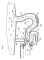
- Fig. 1 is schematically shown a dishwasher with a, a Spülraum limiting rinse tank 1.
- a washing compartment of the washing container 1 a not shown, to be cleaned dishes in dish racks 3, 5 are arranged.
- two spraying arms 7, 8 provided in different spraying levels are arranged by way of example, via which the items to be washed are supplied with washing liquid.
- Spül seideboden is a pump pot 11 with a coarse only indicated sieve assembly 10 is provided. From the sump 11, a recirculation line 9 is guided away with circulating pump 13 arranged therein.
- the circulation line 9 is fluidly connected via supply lines 14, 15 with the spray arms 7, 8.
- the circulating pump 13 is connected downstream, referred to as a water heater heating element 12th
- the sump 11 is also connected via connecting pieces to a, connected to the water supply network fresh water supply line 16 and a drain line 17 in conjunction, in which a drain pump 18 is arranged to pump rinsing liquid from the washing compartment 1.
- the washing container 1 has at its in the Fig. 1 right side as a storage container 19 a so-called storage container, which is thermally coupled in the manner of a heat exchanger in contact with a side wall 20 of the washing compartment 1.
- rinsing liquid can be temporarily stored, which is no longer needed after execution of a partial program step of a rinse cycle.
- the storage tank 19 is in terms of flow in connection with the washing compartment in its upper area via a ventilation opening 22.
- the sump 11 with associated sieve arrangement 10 the recirculation line 9, the feed lines 14, 15 and the two spray arms 7, 8 are integrated in the liquid circuit.
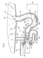
- Downstream of the heating element 12 is provided in the circulation line 9 as a three-way switching valve 25 shown water diverter, at which a connecting line 23 branches off, leading to the storage tank 19.
- the three-way switching valve 25 connects in contrast in a in the Fig. 1 Switching position not shown, the circulation line 9 leading to the storage tank 19 connecting line 23 and interrupts the flow path to the supply lines 14, 15.
- the flushing liquid can be pumped at high flow rate into the storage tank 19 and this fill to clean it storage tank 19 the rinsing liquid enters the rinsing container 1 via the ventilation opening 22 and is fed back along the rinsing container wall 20 past the racks 3, 5 into the sump 11 with associated sieve arrangement 10. In this way, dirt particles, fat residues, etc. can be guided out of the storage container 19.
- a storage tank valve 26 is provided.
- the valve 26 is arranged in the connecting line 23 leading to the storage tank 19 and is arranged in its open position, for example during the above-mentioned storage tank cleaning.
- the rinse cycle can be started with a pre-rinse step, in which a rinse water quantity buffered in the storage container 19 from the previous rinse cycle is introduced into the sump area of the rinse container 1.
- a pre-rinse step in which a rinse water quantity buffered in the storage container 19 from the previous rinse cycle is introduced into the sump area of the rinse container 1.
- the storage tank valve 26 is opened and the three-way valve 25 adjusted accordingly.
- the cached rinse amount can therefore flow alone by gravity into the sump area of the rinse tank 1.
- connection line 23 coming from the storage tank 19 is connected via a mouth opening 29 to a valve space 31 of the storage tank valve 26.
- the valve chamber 31 is radially outside with limited to a nozzle 33.
- the nozzle 33 is connected via two stiffening ribs 35 with the bottom of the storage container 19 in connection.
- the valve chamber 31 also opens at its bottom side via a passage 37 in turn into the connecting line 23, which is connectable via a connecting piece 39 to the water distributor 25.
- the connecting line 23 is proceeding from the bottom-side passage 37 of the valve 26 via a U-shaped bend vertically downwards.
- valve chamber 31 delimiting pipe 33 is used in the present embodiment as a thermal actuator 41, a thermo-actuator, on the valve stem 43 via a valve lift adjustable valve plate 45 is attached.
- the adjustable valve disk 45 is shown in its open position while in the Fig. 3 in its closed position, in which the sealing points 47 of the valve disk 45 and the valve seat 49 are pressed into sealing engagement.
- the valve seat 49 is circumferentially pulled around the mouth opening 29. In this case, the sealing points or sealing surfaces 47 of the valve seat 49 and the valve disk 45 according to the Fig. 3 aligned in a vertical plane.
- the valve plate 47 is according to the 2 to 5 integral part of a membrane element 51, which is formed as a substantially rotationally symmetrical silicone component.
- the rotationally symmetrical membrane element 51 is inserted with its open annular end in an annular gap between the connecting piece 33 and an inner pipe socket 55 of a housing part 57.
- the actuator 41 is therefore not used directly in the connecting piece 33, but with the interposition of the housing part 57th
- a siphon 59 which in the Fig. 3 indicated dirt particles 61 from the valve 26 holds.
- the siphon 49 is guided via a line section 62 directly to the mouth opening 29 of the valve 26.
- the line section 62 of the siphon 59 falls directly from the valve 26 with a rising angle of inclination ⁇ down to the siphon bottom 64th
- the line section 62 of the siphon 59 is thus inclined starting from the mouth opening 29 always on the inclination angle ⁇ down, causing the dirt particles 61 can move under gravity away from the valve 26 to the siphon bottom 64.
- the siphon bottom 64 is arranged below the storage tank valve 26 by a height difference .DELTA.h.
- the actuator 41 has a housing 65 in which a piston 66 is adjustably guided.
- the piston 66 divides the interior of the housing 65 into two working chambers, of which the upper working chamber is filled with a wax material 67, which increases its volume when heat is applied.
- a helical compression spring 68 is arranged, the piston 66 and the associated valve stem 43 in the Fig. 6a pushes up.
- the upper working chamber is also partially bounded by an electrical heating element 69, which may be, for example, a positive temperature coefficient (PTC) resistor.
- PTC positive temperature coefficient
- the thermal actuator 41 is shown in its de-energized state.
- the wax material 67 has a small volume, whereby the spring-biased valve lifter 43 has moved out of the housing 65.
- the valve plate 45 connected to the valve stem 43 would be in the closed position to contact the valve seat 49, as shown in the Fig. 3 and 5 is shown.
- the energized state of the actuator 41 is shown.
- the heating element 69 can heat the wax material 67 in the upper working chamber, thereby increasing its volume.
- the piston 66 is acted upon by a force that is greater than the spring force of the compression spring 68.
- the valve stem 43 is thus retracted against the pressure spring force in the housing 65.
- the Indian Fig. 6b shown state therefore corresponds to the in the Fig. 2 and 4 illustrated open positions of the valve 26th
- valve seat 49 is sharp-edged in the direction of the valve disk 45.
- dirt particles between the valve seat 49 and the valve disk 45 during the closing operation of the valve disk 45 can be severed, as it is based on the Fig. 4 and 5 is shown. Consequently, according to the Fig. 4 a long-drawn dirt particles 61 stuck when emptying the storage container 19 on the valve seat 49.
- the valve plate 45 When closing the valve 26, the valve plate 45 is pressed with great spring force of the compression spring 68 against the valve seat.
- the spring force is dimensioned such that the dirt particles 61 according to the Fig. 5 is severed into two parts, of which a separated part is displaced by the passage 37 under gravity into the further liquid line 23. The other part can also be moved under gravity to Siphonêt 64.
- the storage tank valve 26 is shown in its closed position, whereby the previously pumped into the storage tank 19 rinsing liquid can be cached.
- the dirt particles 61 present in the storage container 19 and in the connecting line 23 therefore deposit over time at the bottom of the storage container 19 and / or on the siphon bottom 64.
- the storage tank valve 26 remains largely free of dirt particles 61 in the area of the sealing surfaces 47.
- the storage tank valve 26 is shown in its open position, in which the valve disk 45 is displaced to the left by one valve lift. In this way, a flow gap between the valve disk 45 and the valve seat 49 is released.
- the rinsing liquid cached in the storage container 19 is thus discharged under gravity from the storage container 19 and passes back into the liquid circulation of the dishwasher.
- the cached rinsing liquid thus flows through the storage tank valve 26 in the flow direction 1.
- the height difference 4h between the storage tank valve 26 and the siphon bottom 64 is designed so that the dirt particles 61 collected at the siphon bottom 64 can not be carried along by the flow 1 for the most part to the storage tank valve 26 ,
Landscapes
- Engineering & Computer Science (AREA)
- General Engineering & Computer Science (AREA)
- Mechanical Engineering (AREA)
- Water Supply & Treatment (AREA)
- Washing And Drying Of Tableware (AREA)
- Lift Valve (AREA)
Applications Claiming Priority (1)
| Application Number | Priority Date | Filing Date | Title |
|---|---|---|---|
| DE102009028275A DE102009028275A1 (de) | 2009-08-06 | 2009-08-06 | Wasserführendes Haushaltsgerät |
Publications (2)
| Publication Number | Publication Date |
|---|---|
| EP2283763A2 true EP2283763A2 (fr) | 2011-02-16 |
| EP2283763A3 EP2283763A3 (fr) | 2017-01-04 |
Family
ID=43415351
Family Applications (1)
| Application Number | Title | Priority Date | Filing Date |
|---|---|---|---|
| EP10170434.4A Withdrawn EP2283763A3 (fr) | 2009-08-06 | 2010-07-22 | Appareil ménager transportant de l'eau |
Country Status (2)
| Country | Link |
|---|---|
| EP (1) | EP2283763A3 (fr) |
| DE (1) | DE102009028275A1 (fr) |
Cited By (3)
| Publication number | Priority date | Publication date | Assignee | Title |
|---|---|---|---|---|
| ITTO20110942A1 (it) * | 2011-10-19 | 2013-04-20 | Indesit Co Spa | Macchina lavastoviglie |
| WO2020156901A1 (fr) * | 2019-01-31 | 2020-08-06 | Gemü Gebr. Müller Apparatebau Gmbh & Co. Kommanditgesellschaft | Moyen d'arrêt |
| CN113494612A (zh) * | 2020-04-01 | 2021-10-12 | 青岛海尔洗碗机有限公司 | 一种水阀结构及洗碗机 |
Families Citing this family (2)
| Publication number | Priority date | Publication date | Assignee | Title |
|---|---|---|---|---|
| CN105769100A (zh) * | 2016-04-15 | 2016-07-20 | 四川汇达通机械设备制造有限公司 | 一种通道式洗碗机喷洗消毒系统 |
| CN105748012A (zh) * | 2016-04-15 | 2016-07-13 | 四川汇达通机械设备制造有限公司 | 一种通道式洗碗机喷洗系统 |
Family Cites Families (6)
| Publication number | Priority date | Publication date | Assignee | Title |
|---|---|---|---|---|
| ES519218A0 (es) * | 1982-01-27 | 1983-12-16 | Eltek Srl | Valvula termoelectrica de una o mas vias. |
| DE3438232A1 (de) * | 1984-10-18 | 1986-04-24 | Bosch-Siemens Hausgeräte GmbH, 7000 Stuttgart | Absperrventil in druckgeminderten fluessigkeitsleitungen von haushalt-geschirrspuelmaschinen |
| IT1183898B (it) * | 1985-06-21 | 1987-10-22 | Eltek Spa | Macchina lavatrice quale lavastoviglie dotata di motore elettrico unico monodirezionale per le funzioni di lavaggio e scarico dell'acqua |
| DE4238450C2 (de) * | 1992-11-13 | 1995-11-16 | Bosch Siemens Hausgeraete | Programmgesteuerte Haushalt-Geschirrspülmaschine |
| DE4243605C2 (de) * | 1992-12-22 | 1998-01-15 | Bosch Siemens Hausgeraete | Haushalt-Geschirrspülmaschine |
| ITPN940011A1 (it) * | 1994-02-25 | 1995-08-25 | Zanussi Elettrodomestici | Lavatrice con sistema di recupero dell'acqua |
-
2009
- 2009-08-06 DE DE102009028275A patent/DE102009028275A1/de not_active Withdrawn
-
2010
- 2010-07-22 EP EP10170434.4A patent/EP2283763A3/fr not_active Withdrawn
Non-Patent Citations (1)
| Title |
|---|
| None |
Cited By (4)
| Publication number | Priority date | Publication date | Assignee | Title |
|---|---|---|---|---|
| ITTO20110942A1 (it) * | 2011-10-19 | 2013-04-20 | Indesit Co Spa | Macchina lavastoviglie |
| EP2583614A3 (fr) * | 2011-10-19 | 2018-04-18 | Whirlpool EMEA S.p.A | Machine lave-vaisselle |
| WO2020156901A1 (fr) * | 2019-01-31 | 2020-08-06 | Gemü Gebr. Müller Apparatebau Gmbh & Co. Kommanditgesellschaft | Moyen d'arrêt |
| CN113494612A (zh) * | 2020-04-01 | 2021-10-12 | 青岛海尔洗碗机有限公司 | 一种水阀结构及洗碗机 |
Also Published As
| Publication number | Publication date |
|---|---|
| EP2283763A3 (fr) | 2017-01-04 |
| DE102009028275A1 (de) | 2011-02-10 |
Similar Documents
| Publication | Publication Date | Title |
|---|---|---|
| EP2283762B1 (fr) | Appareil ménager transportant de l'eau | |
| DE102015207582B4 (de) | Sprüharm und Geschirrspülmaschine | |
| WO2010010012A1 (fr) | Appareil électroménager à circulation d'eau, notamment lave-vaisselle ou lave-linge | |
| EP2185056B1 (fr) | Appareil ménager à circulation d'eau | |
| DE102008061084A1 (de) | Verfahren zum Steuern einer Geschirrspülmaschine | |
| EP1723887A2 (fr) | Lave-vaisselle commerciel, particulièrement machine à laver la verrerie | |
| DE19951838A1 (de) | Geschirrspülmaschine mit einem Spülbehälter | |
| WO2010010166A1 (fr) | Procédé de lavage pour un lave-vaisselle | |
| DE102019131918A1 (de) | Geschirrspülmaschine mit Wärmepumpe | |
| EP2283763A2 (fr) | Appareil ménager transportant de l'eau | |
| DE102009029115A1 (de) | Geschirrspülmaschine sowie Verfahren zum Betrieb einer Geschirrspülmaschine | |
| DE102011077083B4 (de) | Geschirrspülmaschine, insbesondere Haushaltsgeschirrspülmaschine | |
| DE60004058T2 (de) | Verbesserte haushaltgeschirrspülmaschine mit flüssigkeitsverteilungsventil | |
| DE4006621A1 (de) | Elektrisches steuergeraet fuer geschirrspueler | |
| DE102005018879B4 (de) | Geschirrspüler | |
| WO2003073885A1 (fr) | Dispositif de nettoyage de la tete d'un rasoir electrique | |
| DE102009028280B4 (de) | Haushaltsgerät | |
| WO2019072557A1 (fr) | Lave-vaisselle domestique | |
| DE102009002667A1 (de) | Geschirrspülmaschine und Umwälzpumpe mit Wasserweiche | |
| EP2461732B1 (fr) | Appareil ménager à circulation d'eau | |
| DE102011004085B4 (de) | Geschirrspülmaschine mit einer beweglichen Tür und zumindest einer Türdichtung | |
| EP2368477B1 (fr) | Lave-vaisselle avec adoucisseur d'eau et dispositif pour sa régénération | |
| DE4103563A1 (de) | System zur wasser- und reinigungsmittelzufuhr in einem geschirrspueler | |
| DE1703098A1 (de) | Geschirrwaschmaschine | |
| EP3868277B1 (fr) | Bras de lavage |
Legal Events
| Date | Code | Title | Description |
|---|---|---|---|
| PUAI | Public reference made under article 153(3) epc to a published international application that has entered the european phase |
Free format text: ORIGINAL CODE: 0009012 |
|
| AK | Designated contracting states |
Kind code of ref document: A2 Designated state(s): AL AT BE BG CH CY CZ DE DK EE ES FI FR GB GR HR HU IE IS IT LI LT LU LV MC MK MT NL NO PL PT RO SE SI SK SM TR |
|
| AX | Request for extension of the european patent |
Extension state: BA ME RS |
|
| RAP1 | Party data changed (applicant data changed or rights of an application transferred) |
Owner name: BSH HAUSGERAETE GMBH |
|
| PUAL | Search report despatched |
Free format text: ORIGINAL CODE: 0009013 |
|
| AK | Designated contracting states |
Kind code of ref document: A3 Designated state(s): AL AT BE BG CH CY CZ DE DK EE ES FI FR GB GR HR HU IE IS IT LI LT LU LV MC MK MT NL NO PL PT RO SE SI SK SM TR |
|
| AX | Request for extension of the european patent |
Extension state: BA ME RS |
|
| RIC1 | Information provided on ipc code assigned before grant |
Ipc: F16K 31/02 20060101ALI20161129BHEP Ipc: A47L 15/42 20060101AFI20161129BHEP |
|
| STAA | Information on the status of an ep patent application or granted ep patent |
Free format text: STATUS: THE APPLICATION HAS BEEN WITHDRAWN |
|
| 18W | Application withdrawn |
Effective date: 20170531 |