EP2283977A1 - Dispositif de retenue d'outil pour une perceuse - Google Patents
Dispositif de retenue d'outil pour une perceuse Download PDFInfo
- Publication number
- EP2283977A1 EP2283977A1 EP10168427A EP10168427A EP2283977A1 EP 2283977 A1 EP2283977 A1 EP 2283977A1 EP 10168427 A EP10168427 A EP 10168427A EP 10168427 A EP10168427 A EP 10168427A EP 2283977 A1 EP2283977 A1 EP 2283977A1
- Authority
- EP
- European Patent Office
- Prior art keywords
- tool
- tool holder
- holding device
- base plug
- chuck
- Prior art date
- Legal status (The legal status is an assumption and is not a legal conclusion. Google has not performed a legal analysis and makes no representation as to the accuracy of the status listed.)
- Granted
Links
Images


Classifications
-
- B—PERFORMING OPERATIONS; TRANSPORTING
- B25—HAND TOOLS; PORTABLE POWER-DRIVEN TOOLS; MANIPULATORS
- B25D—PERCUSSIVE TOOLS
- B25D17/00—Details of, or accessories for, portable power-driven percussive tools
- B25D17/08—Means for retaining and guiding the tool bit, e.g. chucks allowing axial oscillation of the tool bit
- B25D17/084—Rotating chucks or sockets
-
- B—PERFORMING OPERATIONS; TRANSPORTING
- B23—MACHINE TOOLS; METAL-WORKING NOT OTHERWISE PROVIDED FOR
- B23B—TURNING; BORING
- B23B31/00—Chucks; Expansion mandrels; Adaptations thereof for remote control
- B23B31/008—Chucks; Expansion mandrels; Adaptations thereof for remote control with arrangements for transmitting torque
-
- B—PERFORMING OPERATIONS; TRANSPORTING
- B25—HAND TOOLS; PORTABLE POWER-DRIVEN TOOLS; MANIPULATORS
- B25B—TOOLS OR BENCH DEVICES NOT OTHERWISE PROVIDED FOR, FOR FASTENING, CONNECTING, DISENGAGING, OR HOLDING
- B25B21/00—Portable power-driven screw or nut setting or loosening tools; Attachments for drilling apparatus serving the same purpose
- B25B21/02—Portable power-driven screw or nut setting or loosening tools; Attachments for drilling apparatus serving the same purpose with means for imparting impact to screwdriver blade or nut socket
- B25B21/023—Portable power-driven screw or nut setting or loosening tools; Attachments for drilling apparatus serving the same purpose with means for imparting impact to screwdriver blade or nut socket for imparting an axial impact, e.g. for self-tapping screws
-
- B—PERFORMING OPERATIONS; TRANSPORTING
- B25—HAND TOOLS; PORTABLE POWER-DRIVEN TOOLS; MANIPULATORS
- B25D—PERCUSSIVE TOOLS
- B25D17/00—Details of, or accessories for, portable power-driven percussive tools
- B25D17/005—Attachments or adapters placed between tool and hammer
Definitions
- the invention relates to a tool holding device for a hammer drill according to the preamble of claim 1.
- a hammer drill which receives a tool insert in a rotatably mounted hammer tube, which is acted upon axially frontally by a firing pin.
- the axial locking of the insert tool is achieved by means of a locking ball, which projects through a recess in the hammer tube and is in engagement with a groove on the shaft of the insert tool.
- variously executed insert tools can be included, for example, a screwdriver bit, a hex drill or an SDS drill, provided that the insert tools each have similar shaft parts.
- the invention has the object of providing a rotary hammer versatile use.
- the Tool holder further comprises a change chuck with a second tool holder, wherein the change chuck on the first tool holder of the base plug system is releasably placed and rotatably locked.
- the first tool holder in the base plug-in system is axially open on both sides, so that over the free end an insertion tool is inserted and the opposite end, which is also made open, the impact element or a cooperating with the impact member component of the insert can apply.
- This device has the advantage that various types of plug-in systems can be used on the base plug-in system as well as on the exchangeable chuck, so that differently shaped shank parts of the insert tools in the hammer drill can also be used.
- the base plug-in system is designed to receive screwdriver bits
- the change-over chuck is preferably designed to accommodate SDS tools.
- the respective tool holders in the basic plug-in system and in the change chuck can differ from one another without limiting the functionality of the hammer drill.
- the impact element or a component interacting with the impact element extends through the tool holder in the base plug-in system, so that the axial momentum of the impact element can be transmitted to the insertion tool in the replacement chuck.
- the tool holder of the replaceable chuck is axially open on both sides, so that the impact element in principle also protrude through the open side of the tool holder and can act upon the insertion tool received therein.
- the change-over chuck can optionally be placed on the base plug-in system and locked with it.
- the rotational movement of the drive unit in the hammer drill is first transferred to the first tool holder in the basic plug-in system and from this further on the change chuck or the second tool holder, which is received in the change chuck.
- the first tool holder also serves to connect with the exchangeable chuck to be mounted.
- the first tool holder on the base plug-in system several functions: on the one hand, the connection is made to the change chuck, on the other hand, the rotational movement of the drive unit is transmitted in the hammer drill on the first tool holder on the second tool holder.
- the first tool holder also serves to receive the impact element or a component cooperating therewith in order to be able to transmit the impact effect through the first tool holder to the insertion tool in the second tool holder of the replaceable chuck.
- connection between the basic plug-in system and the change-over chuck basically takes place via the first tool holder, which is part of the base plug-in system, in principle no further connection measures are required, although such additional connecting devices may optionally be provided.
- the first tool holder in the base plug system expediently has a non-round outer contour, in particular a polygonal outer contour, which is designed, for example, as a hexagon.
- a non-round outer contour of the first tool holder allows a positive connection between the base plug system and change chuck in the circumferential direction and thus the transmission of torque about the longitudinal axis of the hammer drill.
- an axial locking device is expediently arranged in the recess in the exchangeable chuck, which can be placed on the first tool holder on the base plug system, which is designed for example as a snap ring or as a locking ball.
- the locking device allows a snap fit between change chuck and base plug system, which can be solved by appropriate application of force again.
- the striking element is preferably formed by a firing pin, which in turn is actuated by a racket, which is received in the housing of the hammer drill.
- the striker acts according to another expedient embodiment, a striker, which protrudes into the first tool holder, which is part of the base plug system.
- the striker is preferably part of the replaceable chuck and protrudes into the recess, which is introduced into the interchangeable chuck and which serves to receive the first tool holder on the base plug-in system.
- an impulse transfer to the insert tool which is received in the second tool holder of the replaceable chuck.
- the striker is hereby acted upon either directly by the racket or by the striker, which in turn is operated by the racket.
- either a change chuck can be used with a recess which is so large in the axial direction that the impact element in the assembled state of the chopper not penetrates up to the recorded in the chuck insert tool.
- a design with a percussion pin detachably received in the recess of the replaceable tool which can be removed from the recess, so that the transfer element for transferring the hammerdriver impulse to the insert tool in the exchangeable chuck is missing. In this way, tool functions can be realized with and without hammer function in the patch change chuck, the hammer drill operation can always remain switched on.
- a manual connection or disconnection of the hammer drill function or an automated connection and disconnection function for example, such that with the placement of the replaceable chuck on the base plug system, the hammer drill function is automatically turned on, if in the recess in the chuck a striker is inserted. If, on the other hand, the striker is missing, the hammer drill function remains switched off.
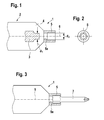
- Fig. 1 shows a tool holding device 1, which is arranged on an end face of a hammer drill 2 and can perform a rotational movement about the hammer drill longitudinal axis 6.
- the hammer drill has a striker on a firing pin 3, which performs an axial impact movement in the direction of the longitudinal axis 6, wherein the impact movement is transferable to an insert tool 7, which is received in a first tool holder 5 on the front side of the base plug 4.
- the tool holder 5 of the base plug 4 in the form of a receiving sleeve forms a hammer tube and is open on the firing pin 3 side facing, so that the front side of the firing pin 3 can act on the rear axial end face of the insert tool 7.
- activated hammer drill function thus exerts the insert tool 7 in the tool holder 5 both a rotational movement and an axial hammer drill movement.
- Fig. 2 the tool holder 5 is shown at the top of the base plug system 4 in plan view.
- the inner contour of the tool holder 5 is designed as a hexagon for receiving an insert tool, the outer contour has a non-circular cross-section.
- the tool holder 5 is particularly suitable for receiving screwdriver bits.
- the tool holder 5 has, as Fig. 1 Further, on the base plug system 4 side facing an inner shoulder 5a with a diameter d 2 , which is slightly larger than the diameter d 1 of the facing tip of the firing pin 3, which protrudes in the hammer holder operation in phases in the tool holder 5.
- the shoulder 5a also forms an abutment for axial limitation during insertion of the insert tool 7 into the tool holder 5, which is shown in FIG Fig. 3 is shown.
- Fig. 4 is an exchange chuck 8 placed on the base plug 4, which forms the tool holder 1 together with the base plug system.
- the change chuck 8 is provided with a tool holder 9, in which an insert tool 10 is detachably inserted.
- a recess 11 is introduced into the change chuck 8, which is placed in the assembled state on the first tool holder 5 of the base plug 4.
- the inner contour of the recess 11 is adapted to the outer contour of the tool holder 5, so that in the direction of rotation a positive connection between the tool holder 5 and 8 exchangeable chuck is given and the rotational movement of the base plug 4 is also transferred to the change chuck 8.
- one or more locking balls 12 are provided, which form locking elements for securing the change-over chuck 8 on the first tool holder 5.
- the firing pin 3 is shown in a state in which the front portion of the firing pin projects axially into the tool holder 5.
- the firing pin 3 is actuated by a racket 13, which is received in the hammer drill.
- the impact movement of the firing pin 3 is transmitted to the insert tool 10 via the axial end face of the firing pin.
- the insert tool 10 is, for example, an SDS drill. It is in principle possible to form the tool holder 5 in the basic plug-in system 4 and the tool holder 9 in the change chuck 8 differently in order to be able to accommodate different insert tools in the base plug-in system 4 and in the change chuck 8.
- Fig. 5 is also a change chuck 8 placed on the base plug system 4.
- the change chuck 8 has, as in the previous embodiment, an axial recess 11 which is placed on the first tool holder 5 in the base plug system 4.
- a striking pin 14 is held on the exchangeable chuck 8, which projects into the recess 11, but has a smaller diameter with respect to the recess 11.
- the striker pin 14 extends into the interior of the first tool holder 5 on the base plug system 4, wherein the free end face of the striker pin faces the racket 13 of the hammer drill and is axially acted upon in the hammer drill operation of the racket 13.
- the striker 14 can execute an axial adjusting movement both in the first tool holder 5 and in relation to the exchangeable chuck 8 and transmits the striking movement in the hammer drill mode of the racket 13 on the insert tool 10, which is received in the second tool holder 9 in the change chuck 8.
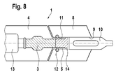
- the embodiment according to Fig. 6 largely corresponds to the one after Fig. 5 , but with the difference that the striker 14, which is held on the change chuck 8 and protrudes in the mounted state in the first tool holder 5 on the base plug 4, is acted upon in the hammer drill operation of the firing pin 3.
- the firing pin 3 is in turn actuated by the racket 13.
- the axial extent of the recess 11 in the change chuck 8 is designed so that the firing pin 3 does not reach the axially rear end face of the insert tool 10. In this way it is ensured that despite activated rotary hammer function, the insert tool 10 is unaffected by the firing pin 3 and only a rotational movement, but no hammer drill movement exerts.
- Fig. 8 essentially corresponds to the one after Fig. 6 , so that reference is made to the description there. at Fig. 8
- the firing pin 3 protrudes axially into the tool holder 5 and thus is at the same time axially in the exchangeable chuck 8. In this way it is avoided that the end face of the firing pin 3 accidentally abuts against the end face of the tool holder 5 in Schlagbohr ceremonies.
Landscapes
- Engineering & Computer Science (AREA)
- Mechanical Engineering (AREA)
- Percussive Tools And Related Accessories (AREA)
Applications Claiming Priority (1)
| Application Number | Priority Date | Filing Date | Title |
|---|---|---|---|
| DE200910028543 DE102009028543A1 (de) | 2009-08-14 | 2009-08-14 | Werkzeughalteeinrichtung für einen Bohrhammer |
Publications (2)
| Publication Number | Publication Date |
|---|---|
| EP2283977A1 true EP2283977A1 (fr) | 2011-02-16 |
| EP2283977B1 EP2283977B1 (fr) | 2017-02-08 |
Family
ID=43088397
Family Applications (1)
| Application Number | Title | Priority Date | Filing Date |
|---|---|---|---|
| EP10168427.2A Not-in-force EP2283977B1 (fr) | 2009-08-14 | 2010-07-05 | Dispositif de retenue d'outil pour une perceuse |
Country Status (3)
| Country | Link |
|---|---|
| EP (1) | EP2283977B1 (fr) |
| CN (1) | CN101992307B (fr) |
| DE (1) | DE102009028543A1 (fr) |
Cited By (6)
| Publication number | Priority date | Publication date | Assignee | Title |
|---|---|---|---|---|
| US8747043B2 (en) | 2010-01-13 | 2014-06-10 | National Nail Corp. | Fastener, installation tool and related method of use |
| US9120214B2 (en) | 2010-01-13 | 2015-09-01 | National Nail Corp. | Fastener, installation tool and related method of use |
| US9144896B2 (en) | 2010-01-13 | 2015-09-29 | National Nail Corp. | Fastener, installation tool and related method of use |
| US9802300B2 (en) | 2010-01-13 | 2017-10-31 | National Nail Corp. | Fastener, installation tool and related method of use |
| US20220048177A1 (en) * | 2020-08-12 | 2022-02-17 | Robert Bosch Gmbh | Hand-Held Power Tool |
| CN114074311B (zh) * | 2020-08-12 | 2026-05-08 | 罗伯特·博世有限公司 | 手持式工具机 |
Citations (2)
| Publication number | Priority date | Publication date | Assignee | Title |
|---|---|---|---|---|
| US20060233622A1 (en) * | 2003-12-23 | 2006-10-19 | Bauman Lynn E | A bit holding apparatus for use with a power tool |
| DE102006016804A1 (de) | 2006-04-10 | 2007-10-11 | Robert Bosch Gmbh | Werkzeughalterung für einen Bohrhammer |
Family Cites Families (3)
| Publication number | Priority date | Publication date | Assignee | Title |
|---|---|---|---|---|
| CN200957552Y (zh) * | 2006-09-04 | 2007-10-10 | 梁宗杰 | 电锤方孔双珠开簧式自锁装置 |
| US8262098B2 (en) * | 2008-02-05 | 2012-09-11 | Robert Bosch Gmbh | Rotary tool system with centering member |
| CN201168957Y (zh) * | 2008-03-07 | 2008-12-24 | 王子建 | 快拆接头结构 |
-
2009
- 2009-08-14 DE DE200910028543 patent/DE102009028543A1/de not_active Withdrawn
-
2010
- 2010-07-05 EP EP10168427.2A patent/EP2283977B1/fr not_active Not-in-force
- 2010-08-09 CN CN201010251321.0A patent/CN101992307B/zh not_active Expired - Fee Related
Patent Citations (2)
| Publication number | Priority date | Publication date | Assignee | Title |
|---|---|---|---|---|
| US20060233622A1 (en) * | 2003-12-23 | 2006-10-19 | Bauman Lynn E | A bit holding apparatus for use with a power tool |
| DE102006016804A1 (de) | 2006-04-10 | 2007-10-11 | Robert Bosch Gmbh | Werkzeughalterung für einen Bohrhammer |
Cited By (9)
| Publication number | Priority date | Publication date | Assignee | Title |
|---|---|---|---|---|
| US8747043B2 (en) | 2010-01-13 | 2014-06-10 | National Nail Corp. | Fastener, installation tool and related method of use |
| US9120214B2 (en) | 2010-01-13 | 2015-09-01 | National Nail Corp. | Fastener, installation tool and related method of use |
| US9144896B2 (en) | 2010-01-13 | 2015-09-29 | National Nail Corp. | Fastener, installation tool and related method of use |
| US9802300B2 (en) | 2010-01-13 | 2017-10-31 | National Nail Corp. | Fastener, installation tool and related method of use |
| US10315295B2 (en) | 2010-01-13 | 2019-06-11 | National Nail Corp. | Fastener, installation tool and related method of use |
| US20220048177A1 (en) * | 2020-08-12 | 2022-02-17 | Robert Bosch Gmbh | Hand-Held Power Tool |
| CN114074311A (zh) * | 2020-08-12 | 2022-02-22 | 罗伯特·博世有限公司 | 手持式工具机 |
| US11981012B2 (en) * | 2020-08-12 | 2024-05-14 | Robert Bosch Gmbh | Hand-held power tool |
| CN114074311B (zh) * | 2020-08-12 | 2026-05-08 | 罗伯特·博世有限公司 | 手持式工具机 |
Also Published As
| Publication number | Publication date |
|---|---|
| CN101992307A (zh) | 2011-03-30 |
| DE102009028543A1 (de) | 2011-02-17 |
| EP2283977B1 (fr) | 2017-02-08 |
| CN101992307B (zh) | 2014-10-29 |
Similar Documents
| Publication | Publication Date | Title |
|---|---|---|
| EP2262601B1 (fr) | Machine-outil a main | |
| EP3261805B1 (fr) | Machine-outil portative | |
| DE19803454B4 (de) | Handgeführte Schlagbohrmaschine mit einer Arretiervorrichtung | |
| EP2295206B1 (fr) | Machine-outil à main électrique combinée | |
| DE19621610B4 (de) | Einrichtung zum Wechseln des Werkzeughalters an einer Handwerkzeugmaschine | |
| DE102014207713B4 (de) | Werkzeugvorsatz für eine Handwerkzeugmaschine | |
| EP3870402B1 (fr) | Clé de service pour porte-outils fixes et entraînés | |
| WO2001021360A1 (fr) | Outil multiple | |
| EP1326736A1 (fr) | Porte-outil pour une machine-outil | |
| EP2283977B1 (fr) | Dispositif de retenue d'outil pour une perceuse | |
| EP1414621B1 (fr) | Machine rotative se presentant approximativement sous forme de perceuse a main, de perceuse a percussion, de marteau perforateur ou de tourne-vis sans fil | |
| WO2009015932A1 (fr) | Machine-outil avec un porte-outil | |
| DE102004026850A1 (de) | Einsteckende für ein drehendes und/oder schlagendes Werkzeug | |
| EP1537956B1 (fr) | Tige pour un outil à percussion, un outil rotatif ou un outil à percussion rotatif | |
| DE3412913A1 (de) | Kombination eines kraftbetriebenen werkzeuges und eines angetriebenen zusatzgeraetes | |
| DE19914577B4 (de) | Werkzeugaufnahme an einem Bohrhammer | |
| EP1938927A2 (fr) | Elément d'entraînement sur une machine-outil manuelle | |
| DE102020201243B3 (de) | Schnellwechselfutter zur reversiblen Arretierung eines Einsteckwerkzeugs an einem Bearbeitungsgerät | |
| EP2345496A1 (fr) | Porte-outil | |
| DE20312887U1 (de) | Beim Betrieb rotierendes Werkzeug mit einem Werkzeugschaft | |
| DE102006015274B4 (de) | Bohrwerkzeuggerät | |
| DE2134781B2 (de) | Setzwerkzeug zum Eintreiben einer Gewindestange | |
| DE3616731C2 (fr) | ||
| DE2653939A1 (de) | Schraubvorsatz fuer handbohrmaschinen | |
| DE102009028546A1 (de) | Werkzeughalteeinrichtung für einen Bohrhammer |
Legal Events
| Date | Code | Title | Description |
|---|---|---|---|
| PUAI | Public reference made under article 153(3) epc to a published international application that has entered the european phase |
Free format text: ORIGINAL CODE: 0009012 |
|
| AK | Designated contracting states |
Kind code of ref document: A1 Designated state(s): AL AT BE BG CH CY CZ DE DK EE ES FI FR GB GR HR HU IE IS IT LI LT LU LV MC MK MT NL NO PL PT RO SE SI SK SM TR |
|
| AX | Request for extension of the european patent |
Extension state: BA ME RS |
|
| 17P | Request for examination filed |
Effective date: 20110816 |
|
| GRAP | Despatch of communication of intention to grant a patent |
Free format text: ORIGINAL CODE: EPIDOSNIGR1 |
|
| INTG | Intention to grant announced |
Effective date: 20161107 |
|
| GRAS | Grant fee paid |
Free format text: ORIGINAL CODE: EPIDOSNIGR3 |
|
| GRAA | (expected) grant |
Free format text: ORIGINAL CODE: 0009210 |
|
| AK | Designated contracting states |
Kind code of ref document: B1 Designated state(s): AL AT BE BG CH CY CZ DE DK EE ES FI FR GB GR HR HU IE IS IT LI LT LU LV MC MK MT NL NO PL PT RO SE SI SK SM TR |
|
| REG | Reference to a national code |
Ref country code: GB Ref legal event code: FG4D Free format text: NOT ENGLISH |
|
| REG | Reference to a national code |
Ref country code: CH Ref legal event code: EP Ref country code: AT Ref legal event code: REF Ref document number: 866655 Country of ref document: AT Kind code of ref document: T Effective date: 20170215 |
|
| REG | Reference to a national code |
Ref country code: IE Ref legal event code: FG4D Free format text: LANGUAGE OF EP DOCUMENT: GERMAN |
|
| REG | Reference to a national code |
Ref country code: DE Ref legal event code: R096 Ref document number: 502010013159 Country of ref document: DE |
|
| REG | Reference to a national code |
Ref country code: LT Ref legal event code: MG4D |
|
| REG | Reference to a national code |
Ref country code: NL Ref legal event code: MP Effective date: 20170208 |
|
| REG | Reference to a national code |
Ref country code: FR Ref legal event code: PLFP Year of fee payment: 8 |
|
| PG25 | Lapsed in a contracting state [announced via postgrant information from national office to epo] |
Ref country code: HR Free format text: LAPSE BECAUSE OF FAILURE TO SUBMIT A TRANSLATION OF THE DESCRIPTION OR TO PAY THE FEE WITHIN THE PRESCRIBED TIME-LIMIT Effective date: 20170208 Ref country code: FI Free format text: LAPSE BECAUSE OF FAILURE TO SUBMIT A TRANSLATION OF THE DESCRIPTION OR TO PAY THE FEE WITHIN THE PRESCRIBED TIME-LIMIT Effective date: 20170208 Ref country code: GR Free format text: LAPSE BECAUSE OF FAILURE TO SUBMIT A TRANSLATION OF THE DESCRIPTION OR TO PAY THE FEE WITHIN THE PRESCRIBED TIME-LIMIT Effective date: 20170509 Ref country code: NO Free format text: LAPSE BECAUSE OF FAILURE TO SUBMIT A TRANSLATION OF THE DESCRIPTION OR TO PAY THE FEE WITHIN THE PRESCRIBED TIME-LIMIT Effective date: 20170508 Ref country code: LT Free format text: LAPSE BECAUSE OF FAILURE TO SUBMIT A TRANSLATION OF THE DESCRIPTION OR TO PAY THE FEE WITHIN THE PRESCRIBED TIME-LIMIT Effective date: 20170208 |
|
| PG25 | Lapsed in a contracting state [announced via postgrant information from national office to epo] |
Ref country code: NL Free format text: LAPSE BECAUSE OF FAILURE TO SUBMIT A TRANSLATION OF THE DESCRIPTION OR TO PAY THE FEE WITHIN THE PRESCRIBED TIME-LIMIT Effective date: 20170208 Ref country code: PT Free format text: LAPSE BECAUSE OF FAILURE TO SUBMIT A TRANSLATION OF THE DESCRIPTION OR TO PAY THE FEE WITHIN THE PRESCRIBED TIME-LIMIT Effective date: 20170608 Ref country code: ES Free format text: LAPSE BECAUSE OF FAILURE TO SUBMIT A TRANSLATION OF THE DESCRIPTION OR TO PAY THE FEE WITHIN THE PRESCRIBED TIME-LIMIT Effective date: 20170208 Ref country code: BG Free format text: LAPSE BECAUSE OF FAILURE TO SUBMIT A TRANSLATION OF THE DESCRIPTION OR TO PAY THE FEE WITHIN THE PRESCRIBED TIME-LIMIT Effective date: 20170508 Ref country code: LV Free format text: LAPSE BECAUSE OF FAILURE TO SUBMIT A TRANSLATION OF THE DESCRIPTION OR TO PAY THE FEE WITHIN THE PRESCRIBED TIME-LIMIT Effective date: 20170208 Ref country code: SE Free format text: LAPSE BECAUSE OF FAILURE TO SUBMIT A TRANSLATION OF THE DESCRIPTION OR TO PAY THE FEE WITHIN THE PRESCRIBED TIME-LIMIT Effective date: 20170208 |
|
| PG25 | Lapsed in a contracting state [announced via postgrant information from national office to epo] |
Ref country code: EE Free format text: LAPSE BECAUSE OF FAILURE TO SUBMIT A TRANSLATION OF THE DESCRIPTION OR TO PAY THE FEE WITHIN THE PRESCRIBED TIME-LIMIT Effective date: 20170208 Ref country code: SK Free format text: LAPSE BECAUSE OF FAILURE TO SUBMIT A TRANSLATION OF THE DESCRIPTION OR TO PAY THE FEE WITHIN THE PRESCRIBED TIME-LIMIT Effective date: 20170208 Ref country code: IT Free format text: LAPSE BECAUSE OF FAILURE TO SUBMIT A TRANSLATION OF THE DESCRIPTION OR TO PAY THE FEE WITHIN THE PRESCRIBED TIME-LIMIT Effective date: 20170208 Ref country code: CZ Free format text: LAPSE BECAUSE OF FAILURE TO SUBMIT A TRANSLATION OF THE DESCRIPTION OR TO PAY THE FEE WITHIN THE PRESCRIBED TIME-LIMIT Effective date: 20170208 Ref country code: RO Free format text: LAPSE BECAUSE OF FAILURE TO SUBMIT A TRANSLATION OF THE DESCRIPTION OR TO PAY THE FEE WITHIN THE PRESCRIBED TIME-LIMIT Effective date: 20170208 |
|
| REG | Reference to a national code |
Ref country code: DE Ref legal event code: R097 Ref document number: 502010013159 Country of ref document: DE |
|
| PG25 | Lapsed in a contracting state [announced via postgrant information from national office to epo] |
Ref country code: SM Free format text: LAPSE BECAUSE OF FAILURE TO SUBMIT A TRANSLATION OF THE DESCRIPTION OR TO PAY THE FEE WITHIN THE PRESCRIBED TIME-LIMIT Effective date: 20170208 Ref country code: PL Free format text: LAPSE BECAUSE OF FAILURE TO SUBMIT A TRANSLATION OF THE DESCRIPTION OR TO PAY THE FEE WITHIN THE PRESCRIBED TIME-LIMIT Effective date: 20170208 Ref country code: DK Free format text: LAPSE BECAUSE OF FAILURE TO SUBMIT A TRANSLATION OF THE DESCRIPTION OR TO PAY THE FEE WITHIN THE PRESCRIBED TIME-LIMIT Effective date: 20170208 |
|
| PLBE | No opposition filed within time limit |
Free format text: ORIGINAL CODE: 0009261 |
|
| STAA | Information on the status of an ep patent application or granted ep patent |
Free format text: STATUS: NO OPPOSITION FILED WITHIN TIME LIMIT |
|
| 26N | No opposition filed |
Effective date: 20171109 |
|
| PG25 | Lapsed in a contracting state [announced via postgrant information from national office to epo] |
Ref country code: SI Free format text: LAPSE BECAUSE OF FAILURE TO SUBMIT A TRANSLATION OF THE DESCRIPTION OR TO PAY THE FEE WITHIN THE PRESCRIBED TIME-LIMIT Effective date: 20170208 |
|
| REG | Reference to a national code |
Ref country code: CH Ref legal event code: PL |
|
| REG | Reference to a national code |
Ref country code: IE Ref legal event code: MM4A |
|
| PG25 | Lapsed in a contracting state [announced via postgrant information from national office to epo] |
Ref country code: IE Free format text: LAPSE BECAUSE OF NON-PAYMENT OF DUE FEES Effective date: 20170705 Ref country code: CH Free format text: LAPSE BECAUSE OF NON-PAYMENT OF DUE FEES Effective date: 20170731 Ref country code: LI Free format text: LAPSE BECAUSE OF NON-PAYMENT OF DUE FEES Effective date: 20170731 |
|
| REG | Reference to a national code |
Ref country code: BE Ref legal event code: MM Effective date: 20170731 |
|
| PG25 | Lapsed in a contracting state [announced via postgrant information from national office to epo] |
Ref country code: LU Free format text: LAPSE BECAUSE OF NON-PAYMENT OF DUE FEES Effective date: 20170705 |
|
| REG | Reference to a national code |
Ref country code: FR Ref legal event code: PLFP Year of fee payment: 9 |
|
| PG25 | Lapsed in a contracting state [announced via postgrant information from national office to epo] |
Ref country code: BE Free format text: LAPSE BECAUSE OF NON-PAYMENT OF DUE FEES Effective date: 20170731 |
|
| REG | Reference to a national code |
Ref country code: AT Ref legal event code: MM01 Ref document number: 866655 Country of ref document: AT Kind code of ref document: T Effective date: 20170705 |
|
| PG25 | Lapsed in a contracting state [announced via postgrant information from national office to epo] |
Ref country code: MT Free format text: LAPSE BECAUSE OF FAILURE TO SUBMIT A TRANSLATION OF THE DESCRIPTION OR TO PAY THE FEE WITHIN THE PRESCRIBED TIME-LIMIT Effective date: 20170208 |
|
| PGFP | Annual fee paid to national office [announced via postgrant information from national office to epo] |
Ref country code: FR Payment date: 20180723 Year of fee payment: 9 |
|
| PG25 | Lapsed in a contracting state [announced via postgrant information from national office to epo] |
Ref country code: AT Free format text: LAPSE BECAUSE OF NON-PAYMENT OF DUE FEES Effective date: 20170705 |
|
| PGFP | Annual fee paid to national office [announced via postgrant information from national office to epo] |
Ref country code: GB Payment date: 20180725 Year of fee payment: 9 |
|
| PG25 | Lapsed in a contracting state [announced via postgrant information from national office to epo] |
Ref country code: HU Free format text: LAPSE BECAUSE OF FAILURE TO SUBMIT A TRANSLATION OF THE DESCRIPTION OR TO PAY THE FEE WITHIN THE PRESCRIBED TIME-LIMIT; INVALID AB INITIO Effective date: 20100705 Ref country code: MC Free format text: LAPSE BECAUSE OF FAILURE TO SUBMIT A TRANSLATION OF THE DESCRIPTION OR TO PAY THE FEE WITHIN THE PRESCRIBED TIME-LIMIT Effective date: 20170208 |
|
| PG25 | Lapsed in a contracting state [announced via postgrant information from national office to epo] |
Ref country code: CY Free format text: LAPSE BECAUSE OF NON-PAYMENT OF DUE FEES Effective date: 20170208 |
|
| PG25 | Lapsed in a contracting state [announced via postgrant information from national office to epo] |
Ref country code: MK Free format text: LAPSE BECAUSE OF FAILURE TO SUBMIT A TRANSLATION OF THE DESCRIPTION OR TO PAY THE FEE WITHIN THE PRESCRIBED TIME-LIMIT Effective date: 20170208 |
|
| GBPC | Gb: european patent ceased through non-payment of renewal fee |
Effective date: 20190705 |
|
| PG25 | Lapsed in a contracting state [announced via postgrant information from national office to epo] |
Ref country code: TR Free format text: LAPSE BECAUSE OF FAILURE TO SUBMIT A TRANSLATION OF THE DESCRIPTION OR TO PAY THE FEE WITHIN THE PRESCRIBED TIME-LIMIT Effective date: 20170208 |
|
| PG25 | Lapsed in a contracting state [announced via postgrant information from national office to epo] |
Ref country code: GB Free format text: LAPSE BECAUSE OF NON-PAYMENT OF DUE FEES Effective date: 20190705 |
|
| PG25 | Lapsed in a contracting state [announced via postgrant information from national office to epo] |
Ref country code: FR Free format text: LAPSE BECAUSE OF NON-PAYMENT OF DUE FEES Effective date: 20190731 |
|
| PG25 | Lapsed in a contracting state [announced via postgrant information from national office to epo] |
Ref country code: AL Free format text: LAPSE BECAUSE OF FAILURE TO SUBMIT A TRANSLATION OF THE DESCRIPTION OR TO PAY THE FEE WITHIN THE PRESCRIBED TIME-LIMIT Effective date: 20170208 Ref country code: IS Free format text: LAPSE BECAUSE OF FAILURE TO SUBMIT A TRANSLATION OF THE DESCRIPTION OR TO PAY THE FEE WITHIN THE PRESCRIBED TIME-LIMIT Effective date: 20170608 |
|
| PGFP | Annual fee paid to national office [announced via postgrant information from national office to epo] |
Ref country code: DE Payment date: 20230922 Year of fee payment: 14 |
|
| REG | Reference to a national code |
Ref country code: DE Ref legal event code: R084 Ref document number: 502010013159 Country of ref document: DE |
|
| REG | Reference to a national code |
Ref country code: DE Ref legal event code: R119 Ref document number: 502010013159 Country of ref document: DE |
|
| PG25 | Lapsed in a contracting state [announced via postgrant information from national office to epo] |
Ref country code: DE Free format text: LAPSE BECAUSE OF NON-PAYMENT OF DUE FEES Effective date: 20250201 |