EP2284009A1 - Bildaufzeichnungsvorrichtung und bildaufzeichnungsverfahren - Google Patents
Bildaufzeichnungsvorrichtung und bildaufzeichnungsverfahren Download PDFInfo
- Publication number
- EP2284009A1 EP2284009A1 EP09762375A EP09762375A EP2284009A1 EP 2284009 A1 EP2284009 A1 EP 2284009A1 EP 09762375 A EP09762375 A EP 09762375A EP 09762375 A EP09762375 A EP 09762375A EP 2284009 A1 EP2284009 A1 EP 2284009A1
- Authority
- EP
- European Patent Office
- Prior art keywords
- recording
- dot
- allocation
- recording element
- element arrays
- Prior art date
- Legal status (The legal status is an assumption and is not a legal conclusion. Google has not performed a legal analysis and makes no representation as to the accuracy of the status listed.)
- Granted
Links
Images




Classifications
-
- B—PERFORMING OPERATIONS; TRANSPORTING
- B41—PRINTING; LINING MACHINES; TYPEWRITERS; STAMPS
- B41J—TYPEWRITERS; SELECTIVE PRINTING MECHANISMS, i.e. MECHANISMS PRINTING OTHERWISE THAN FROM A FORME; CORRECTION OF TYPOGRAPHICAL ERRORS
- B41J2/00—Typewriters or selective printing mechanisms characterised by the printing or marking process for which they are designed
- B41J2/005—Typewriters or selective printing mechanisms characterised by the printing or marking process for which they are designed characterised by bringing liquid or particles selectively into contact with a printing material
- B41J2/01—Ink jet
- B41J2/135—Nozzles
- B41J2/145—Arrangement thereof
- B41J2/155—Arrangement thereof for line printing
-
- B—PERFORMING OPERATIONS; TRANSPORTING
- B41—PRINTING; LINING MACHINES; TYPEWRITERS; STAMPS
- B41J—TYPEWRITERS; SELECTIVE PRINTING MECHANISMS, i.e. MECHANISMS PRINTING OTHERWISE THAN FROM A FORME; CORRECTION OF TYPOGRAPHICAL ERRORS
- B41J2/00—Typewriters or selective printing mechanisms characterised by the printing or marking process for which they are designed
- B41J2/005—Typewriters or selective printing mechanisms characterised by the printing or marking process for which they are designed characterised by bringing liquid or particles selectively into contact with a printing material
- B41J2/01—Ink jet
- B41J2/21—Ink jet for multi-colour printing
- B41J2/2132—Print quality control characterised by dot disposition, e.g. for reducing white stripes or banding
-
- B—PERFORMING OPERATIONS; TRANSPORTING
- B41—PRINTING; LINING MACHINES; TYPEWRITERS; STAMPS
- B41J—TYPEWRITERS; SELECTIVE PRINTING MECHANISMS, i.e. MECHANISMS PRINTING OTHERWISE THAN FROM A FORME; CORRECTION OF TYPOGRAPHICAL ERRORS
- B41J2/00—Typewriters or selective printing mechanisms characterised by the printing or marking process for which they are designed
- B41J2/005—Typewriters or selective printing mechanisms characterised by the printing or marking process for which they are designed characterised by bringing liquid or particles selectively into contact with a printing material
- B41J2/01—Ink jet
- B41J2/21—Ink jet for multi-colour printing
- B41J2/2132—Print quality control characterised by dot disposition, e.g. for reducing white stripes or banding
- B41J2/2146—Print quality control characterised by dot disposition, e.g. for reducing white stripes or banding for line print heads
-
- G—PHYSICS
- G06—COMPUTING OR CALCULATING; COUNTING
- G06K—GRAPHICAL DATA READING; PRESENTATION OF DATA; RECORD CARRIERS; HANDLING RECORD CARRIERS
- G06K2215/00—Arrangements for producing a permanent visual presentation of the output data
- G06K2215/111—Arrangements for producing a permanent visual presentation of the output data with overlapping swaths
-
- H—ELECTRICITY
- H04—ELECTRIC COMMUNICATION TECHNIQUE
- H04N—PICTORIAL COMMUNICATION, e.g. TELEVISION
- H04N1/00—Scanning, transmission or reproduction of documents or the like, e.g. facsimile transmission; Details thereof
- H04N1/04—Scanning arrangements, i.e. arrangements for the displacement of active reading or reproducing elements relative to the original or reproducing medium, or vice versa
- H04N1/19—Scanning arrangements, i.e. arrangements for the displacement of active reading or reproducing elements relative to the original or reproducing medium, or vice versa using multi-element arrays
- H04N1/191—Scanning arrangements, i.e. arrangements for the displacement of active reading or reproducing elements relative to the original or reproducing medium, or vice versa using multi-element arrays the array comprising a one-dimensional [1D] array
- H04N1/1911—Simultaneously or substantially simultaneously scanning picture elements on more than one main scanning line, e.g. scanning in swaths
- H04N1/1912—Scanning main scanning lines which are spaced apart from one another in the sub-scanning direction
-
- H—ELECTRICITY
- H04—ELECTRIC COMMUNICATION TECHNIQUE
- H04N—PICTORIAL COMMUNICATION, e.g. TELEVISION
- H04N1/00—Scanning, transmission or reproduction of documents or the like, e.g. facsimile transmission; Details thereof
- H04N1/40—Picture signal circuits
- H04N1/405—Halftoning, i.e. converting the picture signal of a continuous-tone original into a corresponding signal showing only two levels
- H04N1/4051—Halftoning, i.e. converting the picture signal of a continuous-tone original into a corresponding signal showing only two levels producing a dispersed dots halftone pattern, the dots having substantially the same size
- H04N1/4052—Halftoning, i.e. converting the picture signal of a continuous-tone original into a corresponding signal showing only two levels producing a dispersed dots halftone pattern, the dots having substantially the same size by error diffusion, i.e. transferring the binarising error to neighbouring dot decisions
-
- H—ELECTRICITY
- H04—ELECTRIC COMMUNICATION TECHNIQUE
- H04N—PICTORIAL COMMUNICATION, e.g. TELEVISION
- H04N2201/00—Indexing scheme relating to scanning, transmission or reproduction of documents or the like, and to details thereof
- H04N2201/0077—Types of the still picture apparatus
- H04N2201/0082—Image hardcopy reproducer
Definitions
- Present invention relates to an image recording method and an image recording device where by using a line head including a plurality of recording element arrays arranged in one direction such that the recording elements have overlapping regions at the mutually adjoining end portions thereof, a recording material is attached from the recording element onto a recording medium to form a dot for image printing.
- each of the plurality of recording element arrays may be referred as a short recording element array or a short head, and all of the plurality of recording heads structuring a line head may be referred as a long recording element array or a long head.
- an ink (recording material) from a plurality of nozzles (recording elements) an image is formed on a recording sheet (recording medium).
- an image recording device exists that utilizes a long line head to cover the main scanning direction of the recording sheet.
- recording is performed in the main scanning direction with a state of fixing the line head, and by conveying the recording sheet in the perpendicular direction (sub-scanning direction) to the line head direction (main scanning direction), the image can be formed.
- the log line head to cover the width of the recording sheet has weak points compared to the short head such as high manufacturing cost, low yield ratio at manufacturing, low reliability, further, need of total expensive line head replacement in case of breakage of a part of the recording elements, and high repairing cost is required.
- Patent Document 1 Examined Japanese Patent Application Publication No. H04-38589 .
- a long line head is configured by arranging a plurality of short heads in the direction of nozzle array as shown in Fig. 10 .
- Patent Document 2 Japanese Registration patent No. 370271
- Japanese Registration patent No. 370271 proposed is a method where several recording elements of the short head are overlapped, and the elements are allocated regularly to each head according to the positions, or allocated to disperse irregularly by utilizing random numbers.
- Fig. 12(b) is a pattern when displacement or imbalance of the adjacent short heads is assumed, in the case of Fig. 12(a) .
- one of the adjacent heads is displaced by a distance of 1/2 nozzle pitch from the proper position, and the two heads are assumed to be arranged to displace toward separating direction.
- a highly visible blank portion is generated at the portion where dot density of each adjacent head is reduces.
- three highly visible portions are encircled by dashed lines. In this case, not only generating the blank portions, but also a visible false contour may be generated.
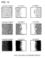
- Fig.13 illustrates results of dot allocation using a conventional technology to each short head in cases of low dot density, half tone pattern of medium dot density and 100% dot density.
- dot allocation utilizing the random numbers is executed to two adjacent short heads near the overlapping region.
- agglomerations are generated in the dot patterns allocated by the use of random numbers ( Fig. 13(b) ⁇ 13(c) ).
- dot densities to be formed by the two short heads are slightly changed.
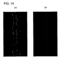
- Fig. 14(a), (b) illustrate dot patterns in the case where in 100% dot ratio image, dot data are allocated to the two short heads, and in addition, each heads is arranged to displaced by 1/2 nozzle pitch in relatively separating direction.
- Fig. 14(a) and Fig. 14(b) there is a difference in the dot allocations to each short heads.
- conventional allocation is executed by the use of random numbers, and there exist large uneven distributions (including low frequency component) in the dot pattern shared by each head in the overlapping region after the allocation.
- Fig. 14(b) allocation is made not to generate the agglomeration of dots in one head by each dot positions, therefore there is no large gap in the dot patterns after allocation in each head in the overlapping region (not including much low frequency component).
- the allocation rule is made by using patterns having blue noise characteristics (characteristics of distributing every dot with a prescribed distance to the neighboring dot) such as a dot pattern generated by half tone processing with error diffusion processing, at least regarding the 100% dot ratio, dot allocation can be executed to each head without unevenness.
- the pattern allocated to each short heads becomes white noise type (the condition including many of the low frequency components), and the uneven dot data allocation as shown in Fig. 13(b1) , (c1) or Fig. 13(b2) , (c2) cannot be improved.
- Present invention is to solve the above described problems, and to realize an image recording method and an image recording device, where image recording is executed by using a line head including a plurality of recording element arrays arranged in one direction such that the recording elements have overlapping regions at the mutually adjoining end portions thereof, wherein image quality degradation by the dislocation of dots and the like in the overlapping region of the adjoining recording element arrays is prevented.
- an inkjet printer is exemplified for a specific example. Accordingly, an ink corresponds to the recording material, and a nozzle for ejecting the ink corresponds to the recording element.
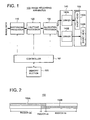
- Controller 101 executes various controls for image formation
- controller 101 executes various controls for conducting a halftone processing step for executing halftone processing of multilevel image data according to a prescribed halftone processing rule (a first halftone processing rule) to form a pattern of dot to be recorded by outputting a recording material from the recording element as a recording pattern; and an allocation processing step for forming a division pattern, based on the recording pattern formed by the halftone processing, for allocating the pattern of dot to be recorded to either of the adjoining overlapping recording element arrays; and a recording step for driving the recording element such that the allocated dot is recorded by the recording element included in each of the short element arrays.
- a halftone processing rule a first halftone processing rule
- Memory section 105 is a storage means to store image data and various types of data, and in the present embodiment specifically stores as matrix patterns various types of data of dither matrix patterns such as a green noise and a blue noise, and a error diffusion matrix pattern to be used for error diffusion process.
- Rasterizing processor 110 is an image processing means for converting various forms of image data such as a vector data received from an external computer into raster data such as a bitmap.
- Halftone processor 120 is a halftone processing means for generating dots in the state of expressing a halftone with error diffusion of multilevel data based on the prescribed halftone processing rule (the first halftone processing rule).
- the halftone processing (having a blue noise property or a green noise property) to suppress the low frequency component is utilized.
- Halftone processor 120 generates the dot to be recorded as a recording pattern by the various processing such as dither, error diffusion, blue noise or green noise as the prescribed halftone processing rule.
- Allocation processor 130 is an allocation processing means for forming a division pattern, for allocating the dot to be recorded to either of the adjoining overlapping recording element arrays, based on the recording pattern formed by the halftone processing, and executing the allocation processing.
- the allocation processor 130 forms, as the prescribed allocation processing rule, an allocation processing rule based on the halftone processing result, consequently the halftone processing and the allocation processing become to have correlation.
- Drive section 140 is a driver means to eject ink by driving each recording elements included in each short head (short recording element array) to be described later.
- drive section 140 is configured with driver 140A and driver 140B.
- Line head 150 is configured as a long recording element array in which a plurality of short line heads (short recording element arrays) arranged in one direction such that the recording elements in each short line heads have overlapping regions at the mutually adjoining end portions.
- line head 150 is configured with short head 150A and short head 150B.
- Fig. 2 shows an aspect to be seen from an ink ejecting side of line head 150.
- the number of recording elements included in each short heads is schematically illustrated, however much more recording elements are actually arranged according to a density of image recording. Further, the line head 150 is actually configured with many more short heads.
- image recording device 100 ejects ink from each recording elements of line head 150 to a recording sheet while conveying the recording sheets by conveyance rollers R1 and R2. Further as necessary, fixing section 160 irradiates heats or ultraviolet rays to the ink on the recording sheet for fixing the recorded image.
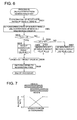
- Fig. 4 illustrates a flow chart showing schematic behaviors at the time of recording of image forming device 100 of the present embodiment.
- rasterizing processor 110 converts various forms of image data such as a vector data received from an external computer into raster data such as a bitmap (step S401 in Fig. 4 ).
- bitmap data from the external or the converted raster data of bitmap format is stored in memory section 105 as necessary.
- image recording device 100 executes a halftone process in order to express the gradation by pseudo gradation using the binary of ejection or non-ejection of the ink (step S402 in Fig. 4 ).
- half tone processor 120 quantizes the multilevel data based on a prescribed halftone processing rule to generate a halftone data (the data corresponding to the dot).
- halftone processor 120 utilized an error diffusion method as the prescribed halftone processing rule, however, commonly known halftone technologies such as a least mean error method or dither method can be used other than the error diffusion method. By this halftone process, the dot data to be recorded is generated.
- data allocation process for each pixel is executed to determine the head associated with the recording of each dot, namely to determine which of the short heads 150A or 150B included in the line head 150 executes the recording (step S403 in Fig. 4 ).
- allocation processor 130 executes the allocation process to form a two-dimensional division pattern distributed in main scanning direction and sub-scanning direction for allocating which of the two adjacent short heads in the overlapping region executes the recording.
- the ink is ejected to the recording sheet to perform image recording (step S404 in Fig. 4 ).
- step S402 in Fig. 4 the halftone process by halftone processor 120 (step S402 in Fig. 4 ), namely dot pattern generation process will be described in detail.
- the halftone processor 120 As the halftone process (step S402 in Fig. 4 ), the halftone processor 120 generates the data processed with the halftone process by executing the process explained below with respect to each pixel of raster data in bitmap format.
- the pixel is the smallest unit to determine whether or not to generate a dot in a print image resolution, and the resolutions of the pixel and the dot are identical with each other.
- this halftone judgment value "total" is equal or less than a threshold value, here equal or less than 127 which being a half value of 1- 255, is determined (step S502 in Fig. 5 ).
- FLAG 1 is set that means to generate a dot, and set a result value #1 to be 255 (step S504 in Fig. 5 ).
- the error component ERR#1 will be obtained.
- the difference between the halftone judgment value "total" and the result value #1 set in step S503 and S504 becomes an error component in the error diffusion.
- this error component ERR#1 is distributed by using a diffusion pattern stored in memory section 105 with diffusion of certain ratio to an unprocessed neighboring dots in the periphery of the subject pixel (step S506 in Fig. 5 ).
- the above described series of processes are executed on the subject pixel shifted in order of the raster. And by executing the halftone process on every pixel, when the coordinate of the subject pixel reached at the final position, the above process terminates.
- controller 101 stores in memory section 105 by correlating to each pixel position.
- step S403 in Fig. 4 data allocation process (step S403 in Fig. 4 ) by allocation processor 130 will be described in detail.
- the data allocation processor 130 determines which of the short heads 150A or 150B is associated with the recording of each dot.
- the allocation processor 130 is specific in generating a division pattern which allocates the recording to either one of the adjoining short recording element arrays in the overlapping region (REGION ab in Fig. 2 ), in accordance with the recording pattern formed in the halftone process.
- the allocation processor 130 determines which of the adjoining short recording element arrays records the dot, by each pixel composing the recording pattern generated by the first halftone process. And the second halftone process has a property of suppressing the low frequency components in two-dimensional spatial frequency domain of each dot data after the allocation, further judgment of allocating the dot at each pixel position to which of the recording element arrays is determined based on result of allocation of the pixel position having been already determined.
- the allocation processor 130 preferably generates the above-described division pattern in such a way as to refer the allocation rate for each short recording element array according to the position in the overlapping region, by taking the error having diffused from an already allocated position into account, to determine which of short recording element arrays records the dot according to the dot generation position in the recording pattern, and to diffuse the error generated by the determination onto neighboring position having not been applied the allocation process.
- the allocation processor 130 utilizing the second halftone process is configured to determine the allocation rate to allocate a dot by each nozzle for one of the short recording element arrays in the overlapping region, and to apply the second halftone processing rule to sequentially determine whether or not to allocate the dot of the recording pattern onto the recording element array by each pixels constituting the recording pattern according to allocation rate, wherein the allocation processor 130 preferably includes:
- An equivalent method to the above-described method can achieve a similar effect to the present embodiment, where by holding the error generated by the allocation at the position having been allocated, and at the time of executing the allocation at the dot generating position in the recording pattern, determined is which of the short recording element arrays is used for recording by taking into account the error being held in the neighboring position having been allocated.
- configurations where the recording pattern is allocated similarly to the present embodiment can achieve the similar effect to the present embodiment, where by utilizing halftone methods such as a blue noise characteristics and a green noise characteristics having suppressed low frequency components and a dot alignment is statistically selected with keeping the distance between dots.
- a matrix for allocating the error to the un-allocated neighboring pixel position, or a matrix for taking the error being held at the pixel position having been allocated into account a distribution coefficient matrix which being utilized in the commonly known error diffusion method or least mean error method may be used.
- the allocation processor 130 determines the allocation rates allotted according to positions for each of the short recording element arrays at the overlapping region (step S601 in Fig. 6 ).
- the allocation rate may be determined at this stage, or the allocation rate may be previously determined and stored in the memory section 105 in order that the allocation processor 130 can read out the allocation rates as necessary via controller 101.
- the allocation rate in the overlapping region of short heads 150A and 150B (REGION ab in Fig. 2 ), for example as shown in Fig. 7 , is determined such that: the allocation rate of adjacent position to not-overlapping region (REGION aa of short head 150A, or REGION bb of short head 150B) is set to be 1.0 (100%), the allocation rate of far end position to the not-overlapping region is set to be 0.0 (0%), and the allocation rates in-between gradually varies with keeping the sum of each short head side rates to be 1.0 (100%). Namely the allocation rate has a property to gradually vary, from 1 to 0, from non-end portion toward end portion, in the overlapping region.
- a flag value is judged which means a recording dot determined in the above halftone process (step S603 in Fig. 6 ).
- step S603 in Fig. 6 since this means not to generate the recording dot, the determination of allocation is not done and set the result value #2 which will be used in a calculation of error diffusion described below, to 0 (step S605 in Fig. 6 ).
- step S606 determination is made to generate the dot at the side of short head 150B, and the result value #2, which will be used for the calculation of error diffusion described below, is set to be 0 (step S606 in Fig. 6 ).
- error component ERR#2 is obtained.
- the difference between the allocation judgment value Drr obtained in step S602 and the result value #2 set in steps S605 - S607 becomes an error component in the error diffusion process.
- the error component corresponds to the quantization error corresponding to the subject pixel in the present invention.
- the error component ERR#2 is distributed to the unprocessed neighboring dots surrounding the subject pixel by diffusing with prescribed rates.
- the error diffusion process in order to express the image by the halftone process, distributes the error generated by the dot allocation process (S605, S606, S607) onto the neighboring pixels, thereafter executes the total allocation process by taking the effect of error distribution into account to minimize the error in total.
- the above allocation process is executed, similarly to the halftone process, with respect to the subject pixel shifted in raster order. And, when the coordinate of the subject pixel reached the final position, the above allocation process completes.
- controller 101 stores in memory section 105 by correlating the each dot to the pixel position.
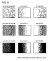
- Fig. 8 corresponds to Fig. 13 which is formed by using the conventional art.
- dot densities formed by the two short heads are somewhat changed from each other.
- dots are evenly allocated as shown in Figs. 8(b1) and 8(c1) without having protruded portions as in Figs. 13(b1) and 13(c1) .
- dots are evenly allocated as shown in Figs. 8(b2) and 8(c2) , without having protruded portions as in Figs. 13(b2) and 13(c2) .
- line head 150 configured with two short heads 150A and 150B is used for simple explanation, the embodiment is applicable to other line head configured with three or more short heads. Specifically, in a case where the third short head (head C) is arranged in the main scanning direction with overlapping to head B through an overlapping region bc, in the region bc the similar allocation process as in the REGION ab can be executed.
- the fixing section 160 is provided, however, the present embodiment is applicable to an image recording device having no fixing section or to an image recording device with a fixing section provided externally to the image recording device.
- the above image forming device is preferable to an inkjet printer, however, is applicable to a recording device or printing device of other system than the inkjet system.
- the recording in the above embodiment does not mean only the recording by ink ejection, but applicable to a luminescent display Namely, the above embodiment is applicable to an image display device that moves a line head configured with a plurality of short heads and conducts luminescent drive.
Landscapes
- Engineering & Computer Science (AREA)
- Quality & Reliability (AREA)
- Ink Jet (AREA)
- Particle Formation And Scattering Control In Inkjet Printers (AREA)
- Color, Gradation (AREA)
- Facsimile Image Signal Circuits (AREA)
Applications Claiming Priority (2)
| Application Number | Priority Date | Filing Date | Title |
|---|---|---|---|
| JP2008150888 | 2008-06-09 | ||
| PCT/JP2009/059860 WO2009150945A1 (ja) | 2008-06-09 | 2009-05-29 | 画像記録方法および画像記録装置 |
Publications (3)
| Publication Number | Publication Date |
|---|---|
| EP2284009A1 true EP2284009A1 (de) | 2011-02-16 |
| EP2284009A4 EP2284009A4 (de) | 2013-08-21 |
| EP2284009B1 EP2284009B1 (de) | 2017-11-22 |
Family
ID=41416656
Family Applications (1)
| Application Number | Title | Priority Date | Filing Date |
|---|---|---|---|
| EP09762375.5A Not-in-force EP2284009B1 (de) | 2008-06-09 | 2009-05-29 | Bildaufzeichnungsvorrichtung und bildaufzeichnungsverfahren |
Country Status (4)
| Country | Link |
|---|---|
| US (1) | US8550589B2 (de) |
| EP (1) | EP2284009B1 (de) |
| JP (1) | JP4983982B2 (de) |
| WO (1) | WO2009150945A1 (de) |
Cited By (1)
| Publication number | Priority date | Publication date | Assignee | Title |
|---|---|---|---|---|
| CN104118214A (zh) * | 2013-04-26 | 2014-10-29 | 海德堡印刷机械股份公司 | 用于产生由区段组成的印刷图像的方法 |
Families Citing this family (6)
| Publication number | Priority date | Publication date | Assignee | Title |
|---|---|---|---|---|
| JP6029343B2 (ja) * | 2012-06-19 | 2016-11-24 | キヤノン株式会社 | 画像処理装置およびその制御方法 |
| US9083912B2 (en) * | 2012-11-06 | 2015-07-14 | Xerox Corporation | Method and apparatus for enabling parallel processing of pixels in an image |
| WO2015098496A1 (ja) * | 2013-12-27 | 2015-07-02 | コニカミノルタ株式会社 | 画像形成装置 |
| JP2019119052A (ja) * | 2017-12-28 | 2019-07-22 | コニカミノルタ株式会社 | 吐出設定方法、データ処理装置及びインクジェット記録装置 |
| JP7081219B2 (ja) * | 2018-03-05 | 2022-06-07 | 株式会社リコー | 液体吐出装置、及びプログラム |
| US12373661B2 (en) | 2023-12-14 | 2025-07-29 | Ricoh Company, Ltd. | Vectorized interleave of bit planes |
Family Cites Families (10)
| Publication number | Priority date | Publication date | Assignee | Title |
|---|---|---|---|---|
| DE3925329A1 (de) | 1989-07-31 | 1991-02-07 | Siemens Ag | Schaltungsanordnung zum regeln der amplitude von videosignalen |
| JPH0438589A (ja) | 1990-06-05 | 1992-02-07 | Tokyo Electric Co Ltd | 郵便用証紙発行装置 |
| US5450099A (en) * | 1993-04-08 | 1995-09-12 | Eastman Kodak Company | Thermal line printer with staggered head segments and overlap compensation |
| JP3702711B2 (ja) | 1999-06-18 | 2005-10-05 | セイコーエプソン株式会社 | 印刷装置および印刷方法 |
| DE60035715T2 (de) * | 2000-05-24 | 2008-04-30 | Silverbrook Research Pty. Ltd., Balmain | Verfahren und vorrichtung zur kompensation von in der zeit variierenden ausrichtefehlern der düsen in einem druckkopf mit gesteuerter tropfenerzeugung |
| JP4229671B2 (ja) | 2002-10-01 | 2009-02-25 | オリンパス株式会社 | 画像記録装置 |
| US7724397B2 (en) * | 2004-12-17 | 2010-05-25 | Hewlett-Packard Development Company, L.P. | Method for compensating for induced artifacts on an image to be printed |
| JP2006305910A (ja) * | 2005-04-28 | 2006-11-09 | Fuji Photo Film Co Ltd | 画像形成方法及び装置 |
| JP4442538B2 (ja) * | 2005-09-22 | 2010-03-31 | 富士ゼロックス株式会社 | 画像処理装置、画像処理方法、画像処理プログラム、及び画像記録装置 |
| JP4254798B2 (ja) * | 2006-04-13 | 2009-04-15 | セイコーエプソン株式会社 | 印刷装置、及び、インク吐出方法の決定方法 |
-
2009
- 2009-05-29 EP EP09762375.5A patent/EP2284009B1/de not_active Not-in-force
- 2009-05-29 US US12/995,814 patent/US8550589B2/en not_active Expired - Fee Related
- 2009-05-29 JP JP2010516809A patent/JP4983982B2/ja not_active Expired - Fee Related
- 2009-05-29 WO PCT/JP2009/059860 patent/WO2009150945A1/ja not_active Ceased
Cited By (3)
| Publication number | Priority date | Publication date | Assignee | Title |
|---|---|---|---|---|
| CN104118214A (zh) * | 2013-04-26 | 2014-10-29 | 海德堡印刷机械股份公司 | 用于产生由区段组成的印刷图像的方法 |
| EP2857207A1 (de) * | 2013-04-26 | 2015-04-08 | Heidelberger Druckmaschinen AG | Verfahren zum Erzeugen eines aus Abschnitten zusammengesetzten Druckbildes |
| US9321260B2 (en) | 2013-04-26 | 2016-04-26 | Heidelberger Druckmaschinen Ag | Method for creating a printed image composed of sections |
Also Published As
| Publication number | Publication date |
|---|---|
| US20110109680A1 (en) | 2011-05-12 |
| JP4983982B2 (ja) | 2012-07-25 |
| US8550589B2 (en) | 2013-10-08 |
| WO2009150945A1 (ja) | 2009-12-17 |
| EP2284009B1 (de) | 2017-11-22 |
| JPWO2009150945A1 (ja) | 2011-11-10 |
| EP2284009A4 (de) | 2013-08-21 |
Similar Documents
| Publication | Publication Date | Title |
|---|---|---|
| US8777343B2 (en) | Image processor, image processing method and inkjet printer involving a print head with parallel nozzle arrays | |
| EP2284009B1 (de) | Bildaufzeichnungsvorrichtung und bildaufzeichnungsverfahren | |
| US8279490B2 (en) | Threshold matrix generating method, image data generating method, image data generating apparatus, image recording apparatus and recording medium | |
| JP6296726B2 (ja) | ディザパタン作成方法および画像処理装置 | |
| JP5595023B2 (ja) | インクジェット記録装置およびデータ生成方法 | |
| US8004719B2 (en) | Threshold matrix generation method, threshold matrix generating apparatus, and recording medium | |
| US8998367B2 (en) | Image processing apparatus and image processing method | |
| US11893288B2 (en) | Threshold matrix generating method | |
| US8194285B2 (en) | Image processing apparatus and image processing method | |
| JP2006306023A (ja) | 印刷装置、印刷プログラム、印刷方法および画像処理装置、画像処理プログラム、画像処理方法、並びに前記プログラムを記録した記録媒体 | |
| JP5366561B2 (ja) | 画像処理装置および画像処理方法 | |
| US8705111B2 (en) | Inkjet printing apparatus and print data generating method | |
| EP2214395A2 (de) | Bildverarbeitungsvorrichtung, Druckvorrichtung und Bildverarbeitungsverfahren | |
| JP7551380B2 (ja) | 画像処理方法及び画像処理装置 | |
| JP2006056080A (ja) | データ処理装置、データ処理方法、インクジェット記録装置、およびインクジェット記録方法 | |
| JP2009279933A (ja) | 画像記録方法および画像記録装置 | |
| US20250117609A1 (en) | Printing apparatus and method of controlling printing apparatus | |
| JP2004175006A (ja) | 記録装置、記録システム、記録方法 | |
| JP2021074972A (ja) | インクジェット記録方法およびインクジェット記録装置 | |
| US20230385584A1 (en) | Printing apparatus, method of controlling printing apparatus, and storage medium | |
| JP2024070387A (ja) | 画像処理装置、印刷装置、及び、画像処理方法 | |
| JP2026011277A (ja) | 印刷装置及び印刷方法 | |
| JP2019123156A (ja) | 画像処理装置、画像処理方法およびインクジェット記録装置 | |
| JP2015202568A (ja) | 記録装置及びその制御方法、データ生成装置、並びに、コンピュータプログラム | |
| JPH09307754A (ja) | 画像処理装置及び画像処理方法 |
Legal Events
| Date | Code | Title | Description |
|---|---|---|---|
| PUAI | Public reference made under article 153(3) epc to a published international application that has entered the european phase |
Free format text: ORIGINAL CODE: 0009012 |
|
| 17P | Request for examination filed |
Effective date: 20101206 |
|
| AK | Designated contracting states |
Kind code of ref document: A1 Designated state(s): AT BE BG CH CY CZ DE DK EE ES FI FR GB GR HR HU IE IS IT LI LT LU LV MC MK MT NL NO PL PT RO SE SI SK TR |
|
| AX | Request for extension of the european patent |
Extension state: AL BA RS |
|
| DAX | Request for extension of the european patent (deleted) | ||
| A4 | Supplementary search report drawn up and despatched |
Effective date: 20130722 |
|
| RIC1 | Information provided on ipc code assigned before grant |
Ipc: B41J 2/155 20060101ALI20130716BHEP Ipc: B41J 2/01 20060101AFI20130716BHEP Ipc: B41J 2/21 20060101ALI20130716BHEP Ipc: B41J 2/205 20060101ALI20130716BHEP |
|
| GRAP | Despatch of communication of intention to grant a patent |
Free format text: ORIGINAL CODE: EPIDOSNIGR1 |
|
| STAA | Information on the status of an ep patent application or granted ep patent |
Free format text: STATUS: GRANT OF PATENT IS INTENDED |
|
| INTG | Intention to grant announced |
Effective date: 20170807 |
|
| GRAS | Grant fee paid |
Free format text: ORIGINAL CODE: EPIDOSNIGR3 |
|
| GRAA | (expected) grant |
Free format text: ORIGINAL CODE: 0009210 |
|
| STAA | Information on the status of an ep patent application or granted ep patent |
Free format text: STATUS: THE PATENT HAS BEEN GRANTED |
|
| AK | Designated contracting states |
Kind code of ref document: B1 Designated state(s): AT BE BG CH CY CZ DE DK EE ES FI FR GB GR HR HU IE IS IT LI LT LU LV MC MK MT NL NO PL PT RO SE SI SK TR |
|
| REG | Reference to a national code |
Ref country code: GB Ref legal event code: FG4D |
|
| REG | Reference to a national code |
Ref country code: CH Ref legal event code: EP |
|
| REG | Reference to a national code |
Ref country code: IE Ref legal event code: FG4D |
|
| REG | Reference to a national code |
Ref country code: AT Ref legal event code: REF Ref document number: 948028 Country of ref document: AT Kind code of ref document: T Effective date: 20171215 |
|
| REG | Reference to a national code |
Ref country code: DE Ref legal event code: R096 Ref document number: 602009049511 Country of ref document: DE |
|
| REG | Reference to a national code |
Ref country code: NL Ref legal event code: MP Effective date: 20171122 |
|
| REG | Reference to a national code |
Ref country code: LT Ref legal event code: MG4D |
|
| REG | Reference to a national code |
Ref country code: AT Ref legal event code: MK05 Ref document number: 948028 Country of ref document: AT Kind code of ref document: T Effective date: 20171122 |
|
| PG25 | Lapsed in a contracting state [announced via postgrant information from national office to epo] |
Ref country code: SE Free format text: LAPSE BECAUSE OF FAILURE TO SUBMIT A TRANSLATION OF THE DESCRIPTION OR TO PAY THE FEE WITHIN THE PRESCRIBED TIME-LIMIT Effective date: 20171122 Ref country code: ES Free format text: LAPSE BECAUSE OF FAILURE TO SUBMIT A TRANSLATION OF THE DESCRIPTION OR TO PAY THE FEE WITHIN THE PRESCRIBED TIME-LIMIT Effective date: 20171122 Ref country code: LT Free format text: LAPSE BECAUSE OF FAILURE TO SUBMIT A TRANSLATION OF THE DESCRIPTION OR TO PAY THE FEE WITHIN THE PRESCRIBED TIME-LIMIT Effective date: 20171122 Ref country code: NL Free format text: LAPSE BECAUSE OF FAILURE TO SUBMIT A TRANSLATION OF THE DESCRIPTION OR TO PAY THE FEE WITHIN THE PRESCRIBED TIME-LIMIT Effective date: 20171122 Ref country code: FI Free format text: LAPSE BECAUSE OF FAILURE TO SUBMIT A TRANSLATION OF THE DESCRIPTION OR TO PAY THE FEE WITHIN THE PRESCRIBED TIME-LIMIT Effective date: 20171122 Ref country code: NO Free format text: LAPSE BECAUSE OF FAILURE TO SUBMIT A TRANSLATION OF THE DESCRIPTION OR TO PAY THE FEE WITHIN THE PRESCRIBED TIME-LIMIT Effective date: 20180222 |
|
| PG25 | Lapsed in a contracting state [announced via postgrant information from national office to epo] |
Ref country code: HR Free format text: LAPSE BECAUSE OF FAILURE TO SUBMIT A TRANSLATION OF THE DESCRIPTION OR TO PAY THE FEE WITHIN THE PRESCRIBED TIME-LIMIT Effective date: 20171122 Ref country code: LV Free format text: LAPSE BECAUSE OF FAILURE TO SUBMIT A TRANSLATION OF THE DESCRIPTION OR TO PAY THE FEE WITHIN THE PRESCRIBED TIME-LIMIT Effective date: 20171122 Ref country code: AT Free format text: LAPSE BECAUSE OF FAILURE TO SUBMIT A TRANSLATION OF THE DESCRIPTION OR TO PAY THE FEE WITHIN THE PRESCRIBED TIME-LIMIT Effective date: 20171122 Ref country code: BG Free format text: LAPSE BECAUSE OF FAILURE TO SUBMIT A TRANSLATION OF THE DESCRIPTION OR TO PAY THE FEE WITHIN THE PRESCRIBED TIME-LIMIT Effective date: 20180222 Ref country code: GR Free format text: LAPSE BECAUSE OF FAILURE TO SUBMIT A TRANSLATION OF THE DESCRIPTION OR TO PAY THE FEE WITHIN THE PRESCRIBED TIME-LIMIT Effective date: 20180223 |
|
| PG25 | Lapsed in a contracting state [announced via postgrant information from national office to epo] |
Ref country code: SK Free format text: LAPSE BECAUSE OF FAILURE TO SUBMIT A TRANSLATION OF THE DESCRIPTION OR TO PAY THE FEE WITHIN THE PRESCRIBED TIME-LIMIT Effective date: 20171122 Ref country code: CY Free format text: LAPSE BECAUSE OF FAILURE TO SUBMIT A TRANSLATION OF THE DESCRIPTION OR TO PAY THE FEE WITHIN THE PRESCRIBED TIME-LIMIT Effective date: 20171122 Ref country code: EE Free format text: LAPSE BECAUSE OF FAILURE TO SUBMIT A TRANSLATION OF THE DESCRIPTION OR TO PAY THE FEE WITHIN THE PRESCRIBED TIME-LIMIT Effective date: 20171122 Ref country code: DK Free format text: LAPSE BECAUSE OF FAILURE TO SUBMIT A TRANSLATION OF THE DESCRIPTION OR TO PAY THE FEE WITHIN THE PRESCRIBED TIME-LIMIT Effective date: 20171122 Ref country code: CZ Free format text: LAPSE BECAUSE OF FAILURE TO SUBMIT A TRANSLATION OF THE DESCRIPTION OR TO PAY THE FEE WITHIN THE PRESCRIBED TIME-LIMIT Effective date: 20171122 |
|
| REG | Reference to a national code |
Ref country code: DE Ref legal event code: R097 Ref document number: 602009049511 Country of ref document: DE |
|
| PG25 | Lapsed in a contracting state [announced via postgrant information from national office to epo] |
Ref country code: RO Free format text: LAPSE BECAUSE OF FAILURE TO SUBMIT A TRANSLATION OF THE DESCRIPTION OR TO PAY THE FEE WITHIN THE PRESCRIBED TIME-LIMIT Effective date: 20171122 Ref country code: IT Free format text: LAPSE BECAUSE OF FAILURE TO SUBMIT A TRANSLATION OF THE DESCRIPTION OR TO PAY THE FEE WITHIN THE PRESCRIBED TIME-LIMIT Effective date: 20171122 Ref country code: PL Free format text: LAPSE BECAUSE OF FAILURE TO SUBMIT A TRANSLATION OF THE DESCRIPTION OR TO PAY THE FEE WITHIN THE PRESCRIBED TIME-LIMIT Effective date: 20171122 |
|
| PLBE | No opposition filed within time limit |
Free format text: ORIGINAL CODE: 0009261 |
|
| STAA | Information on the status of an ep patent application or granted ep patent |
Free format text: STATUS: NO OPPOSITION FILED WITHIN TIME LIMIT |
|
| 26N | No opposition filed |
Effective date: 20180823 |
|
| PG25 | Lapsed in a contracting state [announced via postgrant information from national office to epo] |
Ref country code: SI Free format text: LAPSE BECAUSE OF FAILURE TO SUBMIT A TRANSLATION OF THE DESCRIPTION OR TO PAY THE FEE WITHIN THE PRESCRIBED TIME-LIMIT Effective date: 20171122 |
|
| REG | Reference to a national code |
Ref country code: CH Ref legal event code: PL |
|
| REG | Reference to a national code |
Ref country code: BE Ref legal event code: MM Effective date: 20180531 |
|
| PG25 | Lapsed in a contracting state [announced via postgrant information from national office to epo] |
Ref country code: MC Free format text: LAPSE BECAUSE OF FAILURE TO SUBMIT A TRANSLATION OF THE DESCRIPTION OR TO PAY THE FEE WITHIN THE PRESCRIBED TIME-LIMIT Effective date: 20171122 |
|
| REG | Reference to a national code |
Ref country code: IE Ref legal event code: MM4A |
|
| PG25 | Lapsed in a contracting state [announced via postgrant information from national office to epo] |
Ref country code: CH Free format text: LAPSE BECAUSE OF NON-PAYMENT OF DUE FEES Effective date: 20180531 Ref country code: LI Free format text: LAPSE BECAUSE OF NON-PAYMENT OF DUE FEES Effective date: 20180531 |
|
| PG25 | Lapsed in a contracting state [announced via postgrant information from national office to epo] |
Ref country code: LU Free format text: LAPSE BECAUSE OF NON-PAYMENT OF DUE FEES Effective date: 20180529 |
|
| PG25 | Lapsed in a contracting state [announced via postgrant information from national office to epo] |
Ref country code: FR Free format text: LAPSE BECAUSE OF NON-PAYMENT OF DUE FEES Effective date: 20180531 Ref country code: IE Free format text: LAPSE BECAUSE OF NON-PAYMENT OF DUE FEES Effective date: 20180529 |
|
| PG25 | Lapsed in a contracting state [announced via postgrant information from national office to epo] |
Ref country code: BE Free format text: LAPSE BECAUSE OF NON-PAYMENT OF DUE FEES Effective date: 20180531 |
|
| PG25 | Lapsed in a contracting state [announced via postgrant information from national office to epo] |
Ref country code: MT Free format text: LAPSE BECAUSE OF NON-PAYMENT OF DUE FEES Effective date: 20180529 |
|
| PG25 | Lapsed in a contracting state [announced via postgrant information from national office to epo] |
Ref country code: TR Free format text: LAPSE BECAUSE OF FAILURE TO SUBMIT A TRANSLATION OF THE DESCRIPTION OR TO PAY THE FEE WITHIN THE PRESCRIBED TIME-LIMIT Effective date: 20171122 |
|
| PG25 | Lapsed in a contracting state [announced via postgrant information from national office to epo] |
Ref country code: PT Free format text: LAPSE BECAUSE OF FAILURE TO SUBMIT A TRANSLATION OF THE DESCRIPTION OR TO PAY THE FEE WITHIN THE PRESCRIBED TIME-LIMIT Effective date: 20171122 Ref country code: HU Free format text: LAPSE BECAUSE OF FAILURE TO SUBMIT A TRANSLATION OF THE DESCRIPTION OR TO PAY THE FEE WITHIN THE PRESCRIBED TIME-LIMIT; INVALID AB INITIO Effective date: 20090529 |
|
| PG25 | Lapsed in a contracting state [announced via postgrant information from national office to epo] |
Ref country code: MK Free format text: LAPSE BECAUSE OF NON-PAYMENT OF DUE FEES Effective date: 20171122 |
|
| PG25 | Lapsed in a contracting state [announced via postgrant information from national office to epo] |
Ref country code: IS Free format text: LAPSE BECAUSE OF FAILURE TO SUBMIT A TRANSLATION OF THE DESCRIPTION OR TO PAY THE FEE WITHIN THE PRESCRIBED TIME-LIMIT Effective date: 20180322 |
|
| P01 | Opt-out of the competence of the unified patent court (upc) registered |
Effective date: 20230510 |
|
| PGFP | Annual fee paid to national office [announced via postgrant information from national office to epo] |
Ref country code: GB Payment date: 20240402 Year of fee payment: 16 |
|
| PGFP | Annual fee paid to national office [announced via postgrant information from national office to epo] |
Ref country code: DE Payment date: 20240328 Year of fee payment: 16 |
|
| REG | Reference to a national code |
Ref country code: DE Ref legal event code: R119 Ref document number: 602009049511 Country of ref document: DE |
|
| GBPC | Gb: european patent ceased through non-payment of renewal fee |
Effective date: 20250529 |
|
| PG25 | Lapsed in a contracting state [announced via postgrant information from national office to epo] |
Ref country code: GB Free format text: LAPSE BECAUSE OF NON-PAYMENT OF DUE FEES Effective date: 20250529 |
|
| PG25 | Lapsed in a contracting state [announced via postgrant information from national office to epo] |
Ref country code: DE Free format text: LAPSE BECAUSE OF NON-PAYMENT OF DUE FEES Effective date: 20251202 |