EP2284025A1 - Nutzfahrzeug mit Hinterradantrieb - Google Patents
Nutzfahrzeug mit Hinterradantrieb Download PDFInfo
- Publication number
- EP2284025A1 EP2284025A1 EP09425325A EP09425325A EP2284025A1 EP 2284025 A1 EP2284025 A1 EP 2284025A1 EP 09425325 A EP09425325 A EP 09425325A EP 09425325 A EP09425325 A EP 09425325A EP 2284025 A1 EP2284025 A1 EP 2284025A1
- Authority
- EP
- European Patent Office
- Prior art keywords
- vehicle
- interconnection element
- bodywork
- differential
- interconnection
- Prior art date
- Legal status (The legal status is an assumption and is not a legal conclusion. Google has not performed a legal analysis and makes no representation as to the accuracy of the status listed.)
- Granted
Links
Images



Classifications
-
- B—PERFORMING OPERATIONS; TRANSPORTING
- B60—VEHICLES IN GENERAL
- B60G—VEHICLE SUSPENSION ARRANGEMENTS
- B60G11/00—Resilient suspensions characterised by arrangement, location or kind of springs
- B60G11/02—Resilient suspensions characterised by arrangement, location or kind of springs having leaf springs only
- B60G11/04—Resilient suspensions characterised by arrangement, location or kind of springs having leaf springs only arranged substantially parallel to the longitudinal axis of the vehicle
-
- B—PERFORMING OPERATIONS; TRANSPORTING
- B60—VEHICLES IN GENERAL
- B60G—VEHICLE SUSPENSION ARRANGEMENTS
- B60G11/00—Resilient suspensions characterised by arrangement, location or kind of springs
- B60G11/32—Resilient suspensions characterised by arrangement, location or kind of springs having springs of different kinds
- B60G11/34—Resilient suspensions characterised by arrangement, location or kind of springs having springs of different kinds including leaf springs
- B60G11/38—Resilient suspensions characterised by arrangement, location or kind of springs having springs of different kinds including leaf springs and also rubber springs
-
- B—PERFORMING OPERATIONS; TRANSPORTING
- B60—VEHICLES IN GENERAL
- B60K—ARRANGEMENT OR MOUNTING OF PROPULSION UNITS OR OF TRANSMISSIONS IN VEHICLES; ARRANGEMENT OR MOUNTING OF PLURAL DIVERSE PRIME-MOVERS IN VEHICLES; AUXILIARY DRIVES FOR VEHICLES; INSTRUMENTATION OR DASHBOARDS FOR VEHICLES; ARRANGEMENTS IN CONNECTION WITH COOLING, AIR INTAKE, GAS EXHAUST OR FUEL SUPPLY OF PROPULSION UNITS IN VEHICLES
- B60K17/00—Arrangement or mounting of transmissions in vehicles
- B60K17/04—Arrangement or mounting of transmissions in vehicles characterised by arrangement, location or kind of gearing
- B60K17/16—Arrangement or mounting of transmissions in vehicles characterised by arrangement, location or kind of gearing of differential gearing
-
- B—PERFORMING OPERATIONS; TRANSPORTING
- B60—VEHICLES IN GENERAL
- B60G—VEHICLE SUSPENSION ARRANGEMENTS
- B60G2202/00—Indexing codes relating to the type of spring, damper or actuator
- B60G2202/20—Type of damper
- B60G2202/24—Fluid damper
-
- B—PERFORMING OPERATIONS; TRANSPORTING
- B60—VEHICLES IN GENERAL
- B60G—VEHICLE SUSPENSION ARRANGEMENTS
- B60G2204/00—Indexing codes related to suspensions per se or to auxiliary parts
- B60G2204/10—Mounting of suspension elements
- B60G2204/19—Mounting of transmission differential
-
- B—PERFORMING OPERATIONS; TRANSPORTING
- B60—VEHICLES IN GENERAL
- B60G—VEHICLE SUSPENSION ARRANGEMENTS
- B60G2206/00—Indexing codes related to the manufacturing of suspensions: constructional features, the materials used, procedures or tools
- B60G2206/01—Constructional features of suspension elements, e.g. arms, dampers, springs
- B60G2206/60—Subframe construction
- B60G2206/601—Hanger bracket
-
- B—PERFORMING OPERATIONS; TRANSPORTING
- B60—VEHICLES IN GENERAL
- B60Y—INDEXING SCHEME RELATING TO ASPECTS CROSS-CUTTING VEHICLE TECHNOLOGY
- B60Y2200/00—Type of vehicle
- B60Y2200/10—Road Vehicles
- B60Y2200/14—Trucks; Load vehicles, Busses
Definitions
- the present invention belongs to the field of the manufacturing of industrial vehicles, such as for example commercial vehicles and/or trucks.
- the invention relates to a rear traction commercial vehicle comprising a differential for the distribution of the traction at the rear wheels.
- rear traction commercial vehicles have a rigid axle as integration element between the suspension parts, essentially formed by two leaf springs, and the transmission line.
- the axle shafts usually placed inside the axle, with the function to transfer the motion to the wheel sides, and the differential, usually placed in the middle part of the rear axle.
- a first drawback relates to the positioning of the differential housing in correspondence of the wheel axle.
- the critical point is represented by the dimensions of the housing itself, which, in order to avoid interferences with the bodywork of the vehicle and in particular with the loading platform, requires a limitation of the travel of the suspension.
- the height of the loading platform is, in this kind of vehicles, a key factor, having also a high commercial value, connected to the easiness of use of the vehicle.
- a second drawback of the traditional solutions relates to the driving comfort of the vehicle. Differentials and axle shafts, being integral with the rigid axle, are part of the unsprung masses which affect the vehicle's inertia, in particular of the rear axle. In this case, the need emerges for implementing new solutions which allow to limit the extent of unsprung masses.
- the main task of the present invention is to provide a commercial vehicle which allows to overcome the drawbacks mentioned above.
- a first aim is to realize a loading platform placed at a lower height than the traditional solutions.
- a further aim is to provide a commercial vehicle which presents a higher driving comfort.
- the aim of the present invention is to ensure the same reliability as the traditional solutions, and also an easy manufacturing and industrialization, with competitive costs.
- a rear traction commercial vehicle comprising a bodywork, a pair of rear wheels and a traction assembly (connected to such wheels).
- the traction assembly comprises a differential connected to each wheel by means of a mechanical transmission.
- the vehicle according to the invention comprises a rear suspension assembly comprising an interconnection element for the interconnection between the rear wheels and a pair of spring elements placed between the connection element and the bodywork.
- the interconnection element is independent from the differential, which is suspended to the bodywork of the vehicle. The physical separation of these two components (the interconnection element and the differential) allows to optimize the longitudinal overall dimensions under the bodywork.
- a second remarkable aspect of the present invention relates to the choice to functionally place the interconnection element under the axis of rotation of the two rear wheels; this solution contributes to the reduction of the vertical dimensions of the suspension assembly, allowing a further limitation of the height of the loading platform.
- Another interesting aspect of the present invention relates to the configuration of the interconnection element preferably having a tubular shape comprising a central part folded backwards in order to have enough space for positioning the differential.
- the differential itself has an advantageous rear position, in order to optimize the power transmission to the wheels.
- the rear position of the differential allows to contain the corners of the transmission kinematic chain, with obvious advantages, also in terms of assembling and overall realization costs.
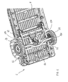
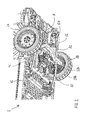
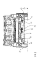
- FIG. 1 shows a bottom view relating to the rear part of a rear traction commercial vehicle 1 according to the present invention.
- vehicle 1 comprises a rear traction assembly with the function of transmitting the motion from the engine to the rear wheels of the vehicle 2A, 2B.
- the traction assembly comprises a propeller shaft (not shown in the figures), a differential 12 from which a mechanical transmission branches off, being formed by two axle shafts 12A, 12B which, by functionally connecting the same differential 12 to the rear wheel hubs, distribute the traction. More in particular, each axle shaft 12A, 12B is connected to the differential 12 by means of a first homokinetic joint (not shown) and is connected to the hub of the relative rear wheel by means of a second homokinetic joint (not shown).
- the differential 12 is suspended to the bodywork 8 of the vehicle 1 in order to be in a substantially central position with respect to the two rear wheels.
- the vehicle 1 also comprises a rear suspension assembly independent from the traction assembly. More in detail, the suspension assembly comprises an interconnection element 11 which transversally connects and supports the rear wheels 2A,2B. Such interconnection element 11 has at its ends two substantially equivalent stanchions 19A,19B, which have the function to support the vehicle loads which, by means of the hubs of the respective wheels 2A,2B are transmitted to the suspension elements.
- Figures 8 and 9 show in detail a possible embodiment of the stanchion elements 19A,19B described below in more detail.
- the suspension assembly also comprises a first spring element 31 and a second spring element 32 constrained to the interconnection element 11 in opposite positions.
- Each spring element 31,32 comprises a leaf spring whose front 36 and rear 37 ends are connected to the bodywork 8 of the vehicle 1 in correspondence of the lower part of the bodywork itself.
- the spring elements of the suspension 31,32 in the following also referred as leaf springs 31,32
- leaf springs 31,32 are functionally placed in symmetric position with respect to the central position of the differential 12. More in particular, each of the leaf springs 31,32 is placed close to one of the rear wheels 2A,2B as better described below.
- the differential 12 is connected to the bodywork 8 preferably in a different longitudinal position with respect to the position of the interconnection element 11. These positions are estimated along a longitudinal direction (see figure 6 ) which develops between the front part (FRONT PART) and the rear part (REAR PART).
- the expression "different longitudinal position” indicates a position of the differential such that it is not placed vertically over the interconnection element 11.
- the differential 12 preferably has a front position with respect to the interconnection element 11, namely towards the front part of the vehicle (FRONT PART).
- the differential 12 may be vertically placed over the interconnection element, remaining separate, however, from the latter.
- the differential 12 is preferably connected to the bodywork 8 by means of a support frame 40 (see figure 7 ) which in the case in point comprises a pair of parallel cross members 42 and a pair of longitudinal support elements 43 which develop in parallel between the two parallel cross members 42.
- the ends 48 of the parallel cross members are constrained to the lower part of the bodywork 8 by means of mechanical connection elements 44.
- the described embodiment has to be considered as a possible, but not exclusive embodiment of the support frame 40, which may have a different configuration, according, for example, to the shape of the bodywork or to the dimensions of the vehicle 1.
- the differential 12 may be directly supported by a shaped portion of the bodywork 8.
- the bodywork 8 may be configured in order to house the differential 12 in one of its portions.
- the differential 12 comprises a housing 17 where the gearing which defines the functionality of the differential itself is housed.
- Such housing 17 is connected to the support frame 40 by means of the rubber connection bushings 55 which allow a higher absorption of the vibrations with obvious advantages.
- the housing 17 has a substantially symmetrical structure with a central part 53 from which a pair of front connection arms 17A and a pair of rear connection arms 17B develop.
- Each arm 17A,17B comprises to one end a rubber bushing 55 pivoting to a connecting portion 57 of the support frame 40.
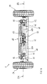
- Figure 6 shows a view in a plan of the suspension assembly of the vehicle shown in the figures from 1 to 5.
- the interconnection element 11 preferably presents a first 11A and a second end part 11B substantially aligned along a transversal reference direction R1 and a central part 11C which develops between the two end parts 11A,11B and which is folded.
- the central part 11C is folded with respect to the two end parts 11A,11C in order to define a space S useful for the positioning of the differential 12.
- the middle part 11C is substantially folded towards the rear part of the vehicle 1 (indicated with REAR PART in figure 6 ).
- the interconnection element 11 is preferably formed by a tubular element with polygonal section which is folded in its central part 11C as indicated above.
- Such element present a substantially rectangular cross section, preferably square.
- This solution is particularly advantageous because it facilitates the connection of the interconnection element to the rear wheels 2A,2B and defines an upper flat rest side 16 for the positioning of the leaf springs as indicated below; moreover the rectangular section, for the same dimensions, allows a higher structural resistance with respect to the circular section of the traditional applications.
- the suspension assembly preferably comprises also a pair of shock absorbing elements 66 (in the following also indicated with the expression pads 66) symmetrically placed with respect to the position of the differential.
- the shock absorbing elements 66 have the function to prevent impacts between the bodywork and the interconnection element 11, by absorbing their relative loads.
- the pads 66 are connected to the interconnection element 11 by means of bolted brackets 68.
- the suspension assembly preferably comprises also a pair of shock absorbers 77, one end 77A of each shock absorber being connected to one of the load bearing elements 19A,19B which support the ends of the interconnection element 11 (see figures 8 and 9 ). While a second end 77B of the shock absorbers 77 is functionally connected to the lower part of the bodywork 8.
- FIGS 8 and 9 show in detail a possible embodiment of the load bearing element 19A which functionally connects the interconnection element to the first wheel 2A.
- the considerations that follow have to be considered as valid also for the second bearing element 19B.
- the first bearing element 19A comprises a first seat 26 geometrically coupled with the end of the interconnection element 11 in order to allow its insertion.
- the load bearing element 19A also comprises a second seat 27 in a position over the first seat 26. In such housing the hub of the first rear wheel 2A is inserted.
- the homokinetic joint connecting the first axle shaft 12A to the first wheel 2A is also functionally placed close to such second seat 27.
- the interconnection element 11 is advantageously positioned under the axis of rotation 101 (indicated in figure 5 ) of the rear wheels 2A,2B.
- This solution allows to further lower the position of the loading platform, ensuring at the same time an adequate structural resistance.
- the use of load bearing elements 19A,19B advantageously facilitates the assembling operations of the vehicle, since such elements may be previously and easily connected to the hubs of the rear wheels 2A,2B and to the interconnection element 11 by means of the relative seats 26.
- the connection between the interconnection element 11 and the load bearing elements 19A,19B by means of a substantially rectangular section ensures a better transmission of the torque, which is no longer left only to welding.
- each shock absorber 77 of the suspension assembly is connected to a respective load bearing element 19A,19B in correspondence of an extension 37 of the latter which laterally comes out with respect to the first seat 26.
- the first end 77A of the shock absorbers is connected to such extension 37 of the load bearing element 19A in order to keep a degree of rotation around an axis substantially parallel to the axis 101 of the rear wheels.
- FIGS 8 and 9 show in detail also a possible embodiment of the connecting element 39 which connects the first leaf spring 31 to the interconnection element 11.
- connecting element 39 comprises a supporting base 75 substantially flat welded to the upper side 16 of the first end 11A of the interconnection element 11.
- the spring 31 is constrained to the supporting base 75 by means of a pair of brackets 79 which close the springs themselves against the supporting base 75. It can be observed that the presence of the upper flat side 16 of the element 11 facilitates the welding of the element 39 and allows the same element to become a simple and reliable structure with obvious advantages in terms of assembling.
- Figures 10 and 11 show in detail a possible embodiment of the front 71 and rear connection means 72 which respectively connect the front 36 and rear end 37 of the first leaf spring 31 to the bodywork 8.
- the front connection means 71 comprise a pair of plates 57 integral with the bodywork 8 between which a rubber bushing 55 pivots, being placed on the front end 36 of the first leaf spring 31.
- the rear connection means 72 comprise instead a pair of connecting rods 73 being opposite and pivoting from one side to a portion 8B of the bodywork 8, and from the other side to the rear end 37 of the first leaf spring 31, also by means of the interposition of a rubber bushing 55. Also in this case the use of rubber bushings 55, for connecting the leaf spring 31, allows a higher absorption of the vibrations.
- the vehicle according to the invention has a bodywork and a loading platform at an height lower than those of the traditional solutions.
- the position of the differential suspended to the bodywork allows an advantageous reduction of the unsprung masses, which results in a high comfort.
- the use of a shaped interconnection element facilitates the positioning of the differential and at the same time facilitates the assembling of the vehicle by virtue of the use of the load bearing elements that are easily connected to the rear wheels.
- the material used and also the dimensions and the shapes may be any, according to the needs and to the state of the art.
Landscapes
- Engineering & Computer Science (AREA)
- Mechanical Engineering (AREA)
- Chemical & Material Sciences (AREA)
- Combustion & Propulsion (AREA)
- Transportation (AREA)
- Vehicle Body Suspensions (AREA)
- Motor Power Transmission Devices (AREA)
- Body Structure For Vehicles (AREA)
Priority Applications (2)
| Application Number | Priority Date | Filing Date | Title |
|---|---|---|---|
| ES09425325T ES2389576T3 (es) | 2009-08-10 | 2009-08-10 | Vehículo comercial de tracción trasera |
| EP20090425325 EP2284025B1 (de) | 2009-08-10 | 2009-08-10 | Nutzfahrzeug mit Hinterradantrieb |
Applications Claiming Priority (1)
| Application Number | Priority Date | Filing Date | Title |
|---|---|---|---|
| EP20090425325 EP2284025B1 (de) | 2009-08-10 | 2009-08-10 | Nutzfahrzeug mit Hinterradantrieb |
Publications (2)
| Publication Number | Publication Date |
|---|---|
| EP2284025A1 true EP2284025A1 (de) | 2011-02-16 |
| EP2284025B1 EP2284025B1 (de) | 2012-06-20 |
Family
ID=41509340
Family Applications (1)
| Application Number | Title | Priority Date | Filing Date |
|---|---|---|---|
| EP20090425325 Active EP2284025B1 (de) | 2009-08-10 | 2009-08-10 | Nutzfahrzeug mit Hinterradantrieb |
Country Status (2)
| Country | Link |
|---|---|
| EP (1) | EP2284025B1 (de) |
| ES (1) | ES2389576T3 (de) |
Citations (9)
| Publication number | Priority date | Publication date | Assignee | Title |
|---|---|---|---|---|
| US2369501A (en) * | 1937-09-17 | 1945-02-13 | Wagner Max | Axle guiding arrangement |
| DE763050C (de) * | 1937-09-17 | 1953-05-18 | Daimler Benz Ag | Abfederung fuer Kraftfahrzeuge |
| GB2061453A (en) * | 1979-09-18 | 1981-05-13 | Nissan Motor | Controlled Vibration Absorber for Use with a Vehicle |
| JPH07228163A (ja) * | 1993-12-24 | 1995-08-29 | Mazda Motor Corp | 車両用駆動装置の取付構造 |
| DE19623936C1 (de) * | 1996-06-15 | 1997-09-04 | Daimler Benz Ag | Lagerung eines Achsgetriebegehäuses eines Kraftfahrzeuges |
| GB2347398A (en) * | 1999-03-04 | 2000-09-06 | Rover Group | Vehicle suspensions |
| WO2003106247A1 (en) * | 2002-06-18 | 2003-12-24 | Arboc Ltd. | Low load floor motor vehicle |
| WO2005012010A1 (en) * | 2003-07-28 | 2005-02-10 | Magna International, Inc. | Frame integrated rear suspension |
| EP1872982A2 (de) * | 2006-06-28 | 2008-01-02 | Dana Corporation | Aufhängungsmontagesystem und Verfahren zu dessen Zusammenbau |
-
2009
- 2009-08-10 EP EP20090425325 patent/EP2284025B1/de active Active
- 2009-08-10 ES ES09425325T patent/ES2389576T3/es active Active
Patent Citations (9)
| Publication number | Priority date | Publication date | Assignee | Title |
|---|---|---|---|---|
| US2369501A (en) * | 1937-09-17 | 1945-02-13 | Wagner Max | Axle guiding arrangement |
| DE763050C (de) * | 1937-09-17 | 1953-05-18 | Daimler Benz Ag | Abfederung fuer Kraftfahrzeuge |
| GB2061453A (en) * | 1979-09-18 | 1981-05-13 | Nissan Motor | Controlled Vibration Absorber for Use with a Vehicle |
| JPH07228163A (ja) * | 1993-12-24 | 1995-08-29 | Mazda Motor Corp | 車両用駆動装置の取付構造 |
| DE19623936C1 (de) * | 1996-06-15 | 1997-09-04 | Daimler Benz Ag | Lagerung eines Achsgetriebegehäuses eines Kraftfahrzeuges |
| GB2347398A (en) * | 1999-03-04 | 2000-09-06 | Rover Group | Vehicle suspensions |
| WO2003106247A1 (en) * | 2002-06-18 | 2003-12-24 | Arboc Ltd. | Low load floor motor vehicle |
| WO2005012010A1 (en) * | 2003-07-28 | 2005-02-10 | Magna International, Inc. | Frame integrated rear suspension |
| EP1872982A2 (de) * | 2006-06-28 | 2008-01-02 | Dana Corporation | Aufhängungsmontagesystem und Verfahren zu dessen Zusammenbau |
Also Published As
| Publication number | Publication date |
|---|---|
| EP2284025B1 (de) | 2012-06-20 |
| ES2389576T3 (es) | 2012-10-29 |
Similar Documents
| Publication | Publication Date | Title |
|---|---|---|
| CA2913353C (en) | Semi-independent suspension system for a low-floor vehicle | |
| CN106457939B (zh) | 车辆悬架 | |
| CN113474200B (zh) | 用于机动车辆的车轴以及具有车轴的机动车辆 | |
| EP0287278B1 (de) | Querträger eines Fahrzeugchassis | |
| US9073400B2 (en) | Motor vehicle multi-link suspension system including a transverse leaf spring | |
| EP1724130A1 (de) | Konsole für eine Luftfeder | |
| CN105073454B (zh) | 用于机动车的轮悬架 | |
| CN100544981C (zh) | 扭杆螺旋弹簧复合悬架装置 | |
| US11072215B2 (en) | Motor vehicle wheel suspension | |
| US11084371B2 (en) | Motor drive device | |
| CN104943490A (zh) | 车辆的单车轮悬挂和带有单车轮悬挂的后桥以及相应配置的车辆 | |
| CN203186026U (zh) | 一种新型mpv后独立悬架系统 | |
| CN111660752A (zh) | 用于电驱动的机动车的扭力梁式车轴 | |
| EP3698998B1 (de) | Hintere aufhängungseinheit für ein fahrzeug mit einer starren achse und einer an der achse montierten elektromotoreinheit | |
| EP3215413B1 (de) | Befestigungsvorrichtung für spurhaltestrebe eines kettenfahrzeuges | |
| US20120161413A1 (en) | Vehicle air suspension | |
| EP2284025B1 (de) | Nutzfahrzeug mit Hinterradantrieb | |
| CN111301526B (zh) | 一种底盘及物流配送车 | |
| EP1241077A1 (de) | Lastkraftwagen mit niedrigem, ebenem Fahrerhausboden | |
| KR20100067312A (ko) | 자동차 로어암 및 쇽업쇼버 브라켓 어셈블리 장치 | |
| CN102729755B (zh) | 车辆的车轮悬架 | |
| CN102282028A (zh) | 弹簧悬架组件 | |
| CN101516650A (zh) | 用于非转向轮的车轮悬架及带有这种车轮悬架的车身 | |
| EP4190601B1 (de) | Fahrzeug mit einem verbesserten aufhängungssystem | |
| KR102018137B1 (ko) | 대형 상용차량용 서스펜션에 적용되는 토크로드 구조체 |
Legal Events
| Date | Code | Title | Description |
|---|---|---|---|
| PUAI | Public reference made under article 153(3) epc to a published international application that has entered the european phase |
Free format text: ORIGINAL CODE: 0009012 |
|
| AK | Designated contracting states |
Kind code of ref document: A1 Designated state(s): AT BE BG CH CY CZ DE DK EE ES FI FR GB GR HR HU IE IS IT LI LT LU LV MC MK MT NL NO PL PT RO SE SI SK SM TR |
|
| AX | Request for extension of the european patent |
Extension state: AL BA RS |
|
| 17P | Request for examination filed |
Effective date: 20110530 |
|
| GRAP | Despatch of communication of intention to grant a patent |
Free format text: ORIGINAL CODE: EPIDOSNIGR1 |
|
| RIC1 | Information provided on ipc code assigned before grant |
Ipc: B60G 11/38 20060101ALI20111207BHEP Ipc: B60G 9/00 20060101AFI20111207BHEP Ipc: B60K 17/16 20060101ALI20111207BHEP Ipc: B60G 11/04 20060101ALI20111207BHEP |
|
| GRAS | Grant fee paid |
Free format text: ORIGINAL CODE: EPIDOSNIGR3 |
|
| GRAA | (expected) grant |
Free format text: ORIGINAL CODE: 0009210 |
|
| AK | Designated contracting states |
Kind code of ref document: B1 Designated state(s): AT BE BG CH CY CZ DE DK EE ES FI FR GB GR HR HU IE IS IT LI LT LU LV MC MK MT NL NO PL PT RO SE SI SK SM TR |
|
| REG | Reference to a national code |
Ref country code: GB Ref legal event code: FG4D |
|
| REG | Reference to a national code |
Ref country code: CH Ref legal event code: EP |
|
| REG | Reference to a national code |
Ref country code: AT Ref legal event code: REF Ref document number: 562832 Country of ref document: AT Kind code of ref document: T Effective date: 20120715 |
|
| REG | Reference to a national code |
Ref country code: IE Ref legal event code: FG4D |
|
| REG | Reference to a national code |
Ref country code: CH Ref legal event code: NV Representative=s name: N&G PATENT SERVICES SA |
|
| REG | Reference to a national code |
Ref country code: DE Ref legal event code: R096 Ref document number: 602009007698 Country of ref document: DE Effective date: 20120816 |
|
| REG | Reference to a national code |
Ref country code: SE Ref legal event code: TRGR |
|
| REG | Reference to a national code |
Ref country code: NL Ref legal event code: T3 |
|
| REG | Reference to a national code |
Ref country code: ES Ref legal event code: FG2A Ref document number: 2389576 Country of ref document: ES Kind code of ref document: T3 Effective date: 20121029 |
|
| PG25 | Lapsed in a contracting state [announced via postgrant information from national office to epo] |
Ref country code: NO Free format text: LAPSE BECAUSE OF FAILURE TO SUBMIT A TRANSLATION OF THE DESCRIPTION OR TO PAY THE FEE WITHIN THE PRESCRIBED TIME-LIMIT Effective date: 20120920 Ref country code: FI Free format text: LAPSE BECAUSE OF FAILURE TO SUBMIT A TRANSLATION OF THE DESCRIPTION OR TO PAY THE FEE WITHIN THE PRESCRIBED TIME-LIMIT Effective date: 20120620 Ref country code: LT Free format text: LAPSE BECAUSE OF FAILURE TO SUBMIT A TRANSLATION OF THE DESCRIPTION OR TO PAY THE FEE WITHIN THE PRESCRIBED TIME-LIMIT Effective date: 20120620 |
|
| REG | Reference to a national code |
Ref country code: AT Ref legal event code: MK05 Ref document number: 562832 Country of ref document: AT Kind code of ref document: T Effective date: 20120620 |
|
| REG | Reference to a national code |
Ref country code: LT Ref legal event code: MG4D Effective date: 20120620 |
|
| PG25 | Lapsed in a contracting state [announced via postgrant information from national office to epo] |
Ref country code: GR Free format text: LAPSE BECAUSE OF FAILURE TO SUBMIT A TRANSLATION OF THE DESCRIPTION OR TO PAY THE FEE WITHIN THE PRESCRIBED TIME-LIMIT Effective date: 20120921 Ref country code: LV Free format text: LAPSE BECAUSE OF FAILURE TO SUBMIT A TRANSLATION OF THE DESCRIPTION OR TO PAY THE FEE WITHIN THE PRESCRIBED TIME-LIMIT Effective date: 20120620 Ref country code: HR Free format text: LAPSE BECAUSE OF FAILURE TO SUBMIT A TRANSLATION OF THE DESCRIPTION OR TO PAY THE FEE WITHIN THE PRESCRIBED TIME-LIMIT Effective date: 20120620 Ref country code: SI Free format text: LAPSE BECAUSE OF FAILURE TO SUBMIT A TRANSLATION OF THE DESCRIPTION OR TO PAY THE FEE WITHIN THE PRESCRIBED TIME-LIMIT Effective date: 20120620 |
|
| PG25 | Lapsed in a contracting state [announced via postgrant information from national office to epo] |
Ref country code: SK Free format text: LAPSE BECAUSE OF FAILURE TO SUBMIT A TRANSLATION OF THE DESCRIPTION OR TO PAY THE FEE WITHIN THE PRESCRIBED TIME-LIMIT Effective date: 20120620 Ref country code: RO Free format text: LAPSE BECAUSE OF FAILURE TO SUBMIT A TRANSLATION OF THE DESCRIPTION OR TO PAY THE FEE WITHIN THE PRESCRIBED TIME-LIMIT Effective date: 20120620 Ref country code: IS Free format text: LAPSE BECAUSE OF FAILURE TO SUBMIT A TRANSLATION OF THE DESCRIPTION OR TO PAY THE FEE WITHIN THE PRESCRIBED TIME-LIMIT Effective date: 20121020 Ref country code: BE Free format text: LAPSE BECAUSE OF FAILURE TO SUBMIT A TRANSLATION OF THE DESCRIPTION OR TO PAY THE FEE WITHIN THE PRESCRIBED TIME-LIMIT Effective date: 20120620 Ref country code: CZ Free format text: LAPSE BECAUSE OF FAILURE TO SUBMIT A TRANSLATION OF THE DESCRIPTION OR TO PAY THE FEE WITHIN THE PRESCRIBED TIME-LIMIT Effective date: 20120620 Ref country code: AT Free format text: LAPSE BECAUSE OF FAILURE TO SUBMIT A TRANSLATION OF THE DESCRIPTION OR TO PAY THE FEE WITHIN THE PRESCRIBED TIME-LIMIT Effective date: 20120620 Ref country code: CY Free format text: LAPSE BECAUSE OF FAILURE TO SUBMIT A TRANSLATION OF THE DESCRIPTION OR TO PAY THE FEE WITHIN THE PRESCRIBED TIME-LIMIT Effective date: 20120620 Ref country code: EE Free format text: LAPSE BECAUSE OF FAILURE TO SUBMIT A TRANSLATION OF THE DESCRIPTION OR TO PAY THE FEE WITHIN THE PRESCRIBED TIME-LIMIT Effective date: 20120620 |
|
| PG25 | Lapsed in a contracting state [announced via postgrant information from national office to epo] |
Ref country code: PL Free format text: LAPSE BECAUSE OF FAILURE TO SUBMIT A TRANSLATION OF THE DESCRIPTION OR TO PAY THE FEE WITHIN THE PRESCRIBED TIME-LIMIT Effective date: 20120620 Ref country code: PT Free format text: LAPSE BECAUSE OF FAILURE TO SUBMIT A TRANSLATION OF THE DESCRIPTION OR TO PAY THE FEE WITHIN THE PRESCRIBED TIME-LIMIT Effective date: 20121022 |
|
| PG25 | Lapsed in a contracting state [announced via postgrant information from national office to epo] |
Ref country code: MC Free format text: LAPSE BECAUSE OF NON-PAYMENT OF DUE FEES Effective date: 20120831 |
|
| PLBE | No opposition filed within time limit |
Free format text: ORIGINAL CODE: 0009261 |
|
| STAA | Information on the status of an ep patent application or granted ep patent |
Free format text: STATUS: NO OPPOSITION FILED WITHIN TIME LIMIT |
|
| PG25 | Lapsed in a contracting state [announced via postgrant information from national office to epo] |
Ref country code: DK Free format text: LAPSE BECAUSE OF FAILURE TO SUBMIT A TRANSLATION OF THE DESCRIPTION OR TO PAY THE FEE WITHIN THE PRESCRIBED TIME-LIMIT Effective date: 20120620 |
|
| REG | Reference to a national code |
Ref country code: IE Ref legal event code: MM4A |
|
| 26N | No opposition filed |
Effective date: 20130321 |
|
| REG | Reference to a national code |
Ref country code: DE Ref legal event code: R097 Ref document number: 602009007698 Country of ref document: DE Effective date: 20130321 |
|
| PG25 | Lapsed in a contracting state [announced via postgrant information from national office to epo] |
Ref country code: IE Free format text: LAPSE BECAUSE OF NON-PAYMENT OF DUE FEES Effective date: 20120810 Ref country code: BG Free format text: LAPSE BECAUSE OF FAILURE TO SUBMIT A TRANSLATION OF THE DESCRIPTION OR TO PAY THE FEE WITHIN THE PRESCRIBED TIME-LIMIT Effective date: 20120920 |
|
| PG25 | Lapsed in a contracting state [announced via postgrant information from national office to epo] |
Ref country code: MT Free format text: LAPSE BECAUSE OF FAILURE TO SUBMIT A TRANSLATION OF THE DESCRIPTION OR TO PAY THE FEE WITHIN THE PRESCRIBED TIME-LIMIT Effective date: 20120620 |
|
| PG25 | Lapsed in a contracting state [announced via postgrant information from national office to epo] |
Ref country code: TR Free format text: LAPSE BECAUSE OF FAILURE TO SUBMIT A TRANSLATION OF THE DESCRIPTION OR TO PAY THE FEE WITHIN THE PRESCRIBED TIME-LIMIT Effective date: 20120620 |
|
| PG25 | Lapsed in a contracting state [announced via postgrant information from national office to epo] |
Ref country code: SM Free format text: LAPSE BECAUSE OF FAILURE TO SUBMIT A TRANSLATION OF THE DESCRIPTION OR TO PAY THE FEE WITHIN THE PRESCRIBED TIME-LIMIT Effective date: 20120620 Ref country code: LU Free format text: LAPSE BECAUSE OF NON-PAYMENT OF DUE FEES Effective date: 20120810 |
|
| PG25 | Lapsed in a contracting state [announced via postgrant information from national office to epo] |
Ref country code: HU Free format text: LAPSE BECAUSE OF FAILURE TO SUBMIT A TRANSLATION OF THE DESCRIPTION OR TO PAY THE FEE WITHIN THE PRESCRIBED TIME-LIMIT Effective date: 20090810 |
|
| REG | Reference to a national code |
Ref country code: FR Ref legal event code: PLFP Year of fee payment: 7 |
|
| PG25 | Lapsed in a contracting state [announced via postgrant information from national office to epo] |
Ref country code: MK Free format text: LAPSE BECAUSE OF FAILURE TO SUBMIT A TRANSLATION OF THE DESCRIPTION OR TO PAY THE FEE WITHIN THE PRESCRIBED TIME-LIMIT Effective date: 20120620 |
|
| REG | Reference to a national code |
Ref country code: FR Ref legal event code: PLFP Year of fee payment: 8 |
|
| REG | Reference to a national code |
Ref country code: FR Ref legal event code: PLFP Year of fee payment: 9 |
|
| PGFP | Annual fee paid to national office [announced via postgrant information from national office to epo] |
Ref country code: NL Payment date: 20170814 Year of fee payment: 9 |
|
| PGFP | Annual fee paid to national office [announced via postgrant information from national office to epo] |
Ref country code: CH Payment date: 20170814 Year of fee payment: 9 |
|
| PGFP | Annual fee paid to national office [announced via postgrant information from national office to epo] |
Ref country code: SE Payment date: 20170810 Year of fee payment: 9 |
|
| REG | Reference to a national code |
Ref country code: FR Ref legal event code: PLFP Year of fee payment: 10 |
|
| REG | Reference to a national code |
Ref country code: CH Ref legal event code: PL |
|
| REG | Reference to a national code |
Ref country code: SE Ref legal event code: EUG |
|
| REG | Reference to a national code |
Ref country code: NL Ref legal event code: MM Effective date: 20180901 |
|
| PG25 | Lapsed in a contracting state [announced via postgrant information from national office to epo] |
Ref country code: LI Free format text: LAPSE BECAUSE OF NON-PAYMENT OF DUE FEES Effective date: 20180831 Ref country code: CH Free format text: LAPSE BECAUSE OF NON-PAYMENT OF DUE FEES Effective date: 20180831 |
|
| PG25 | Lapsed in a contracting state [announced via postgrant information from national office to epo] |
Ref country code: SE Free format text: LAPSE BECAUSE OF NON-PAYMENT OF DUE FEES Effective date: 20180811 |
|
| PG25 | Lapsed in a contracting state [announced via postgrant information from national office to epo] |
Ref country code: NL Free format text: LAPSE BECAUSE OF NON-PAYMENT OF DUE FEES Effective date: 20180901 |
|
| P01 | Opt-out of the competence of the unified patent court (upc) registered |
Effective date: 20230523 |
|
| PGFP | Annual fee paid to national office [announced via postgrant information from national office to epo] |
Ref country code: ES Payment date: 20250916 Year of fee payment: 17 |
|
| PGFP | Annual fee paid to national office [announced via postgrant information from national office to epo] |
Ref country code: DE Payment date: 20250827 Year of fee payment: 17 |
|
| PGFP | Annual fee paid to national office [announced via postgrant information from national office to epo] |
Ref country code: IT Payment date: 20250714 Year of fee payment: 17 |
|
| PGFP | Annual fee paid to national office [announced via postgrant information from national office to epo] |
Ref country code: GB Payment date: 20250826 Year of fee payment: 17 |
|
| PGFP | Annual fee paid to national office [announced via postgrant information from national office to epo] |
Ref country code: FR Payment date: 20250825 Year of fee payment: 17 |