EP2284036A2 - Générateur d'énergie exploitant une charge appliquée sur un pneu - Google Patents
Générateur d'énergie exploitant une charge appliquée sur un pneu Download PDFInfo
- Publication number
- EP2284036A2 EP2284036A2 EP09733527A EP09733527A EP2284036A2 EP 2284036 A2 EP2284036 A2 EP 2284036A2 EP 09733527 A EP09733527 A EP 09733527A EP 09733527 A EP09733527 A EP 09733527A EP 2284036 A2 EP2284036 A2 EP 2284036A2
- Authority
- EP
- European Patent Office
- Prior art keywords
- tire
- housing
- electricity
- power generator
- hydraulic
- Prior art date
- Legal status (The legal status is an assumption and is not a legal conclusion. Google has not performed a legal analysis and makes no representation as to the accuracy of the status listed.)
- Withdrawn
Links
Images




Classifications
-
- H—ELECTRICITY
- H02—GENERATION; CONVERSION OR DISTRIBUTION OF ELECTRIC POWER
- H02K—DYNAMO-ELECTRIC MACHINES
- H02K7/00—Arrangements for handling mechanical energy structurally associated with dynamo-electric machines, e.g. structural association with mechanical driving motors or auxiliary dynamo-electric machines
- H02K7/18—Structural association of electric generators with mechanical driving motors, e.g. with turbines
- H02K7/1807—Rotary generators
- H02K7/1846—Rotary generators structurally associated with wheels or associated parts
-
- B—PERFORMING OPERATIONS; TRANSPORTING
- B60—VEHICLES IN GENERAL
- B60K—ARRANGEMENT OR MOUNTING OF PROPULSION UNITS OR OF TRANSMISSIONS IN VEHICLES; ARRANGEMENT OR MOUNTING OF PLURAL DIVERSE PRIME-MOVERS IN VEHICLES; AUXILIARY DRIVES FOR VEHICLES; INSTRUMENTATION OR DASHBOARDS FOR VEHICLES; ARRANGEMENTS IN CONNECTION WITH COOLING, AIR INTAKE, GAS EXHAUST OR FUEL SUPPLY OF PROPULSION UNITS IN VEHICLES
- B60K25/00—Auxiliary drives
- B60K25/08—Auxiliary drives from a ground wheel, e.g. engaging the wheel tread or rim
-
- F—MECHANICAL ENGINEERING; LIGHTING; HEATING; WEAPONS; BLASTING
- F03—MACHINES OR ENGINES FOR LIQUIDS; WIND, SPRING, OR WEIGHT MOTORS; PRODUCING MECHANICAL POWER OR A REACTIVE PROPULSIVE THRUST, NOT OTHERWISE PROVIDED FOR
- F03G—SPRING, WEIGHT, INERTIA OR LIKE MOTORS; MECHANICAL-POWER PRODUCING DEVICES OR MECHANISMS, NOT OTHERWISE PROVIDED FOR OR USING ENERGY SOURCES NOT OTHERWISE PROVIDED FOR
- F03G7/00—Mechanical-power-producing mechanisms, not otherwise provided for or using energy sources not otherwise provided for
- F03G7/08—Mechanical-power-producing mechanisms, not otherwise provided for or using energy sources not otherwise provided for recovering energy derived from swinging, rolling, pitching or like movements, e.g. from the vibrations of a machine
- F03G7/081—Mechanical-power-producing mechanisms, not otherwise provided for or using energy sources not otherwise provided for recovering energy derived from swinging, rolling, pitching or like movements, e.g. from the vibrations of a machine recovering energy from moving road or rail vehicles, e.g. collecting vehicle vibrations in the vehicle tyres or shock absorbers
-
- B—PERFORMING OPERATIONS; TRANSPORTING
- B60—VEHICLES IN GENERAL
- B60L—PROPULSION OF ELECTRICALLY-PROPELLED VEHICLES; SUPPLYING ELECTRIC POWER FOR AUXILIARY EQUIPMENT OF ELECTRICALLY-PROPELLED VEHICLES; ELECTRODYNAMIC BRAKE SYSTEMS FOR VEHICLES IN GENERAL; MAGNETIC SUSPENSION OR LEVITATION FOR VEHICLES; MONITORING OPERATING VARIABLES OF ELECTRICALLY-PROPELLED VEHICLES; ELECTRIC SAFETY DEVICES FOR ELECTRICALLY-PROPELLED VEHICLES
- B60L2220/00—Electrical machine types; Structures or applications thereof
- B60L2220/40—Electrical machine applications
- B60L2220/44—Wheel Hub motors, i.e. integrated in the wheel hub
-
- Y—GENERAL TAGGING OF NEW TECHNOLOGICAL DEVELOPMENTS; GENERAL TAGGING OF CROSS-SECTIONAL TECHNOLOGIES SPANNING OVER SEVERAL SECTIONS OF THE IPC; TECHNICAL SUBJECTS COVERED BY FORMER USPC CROSS-REFERENCE ART COLLECTIONS [XRACs] AND DIGESTS
- Y02—TECHNOLOGIES OR APPLICATIONS FOR MITIGATION OR ADAPTATION AGAINST CLIMATE CHANGE
- Y02T—CLIMATE CHANGE MITIGATION TECHNOLOGIES RELATED TO TRANSPORTATION
- Y02T10/00—Road transport of goods or passengers
- Y02T10/60—Other road transportation technologies with climate change mitigation effect
- Y02T10/64—Electric machine technologies in electromobility
-
- Y—GENERAL TAGGING OF NEW TECHNOLOGICAL DEVELOPMENTS; GENERAL TAGGING OF CROSS-SECTIONAL TECHNOLOGIES SPANNING OVER SEVERAL SECTIONS OF THE IPC; TECHNICAL SUBJECTS COVERED BY FORMER USPC CROSS-REFERENCE ART COLLECTIONS [XRACs] AND DIGESTS
- Y02—TECHNOLOGIES OR APPLICATIONS FOR MITIGATION OR ADAPTATION AGAINST CLIMATE CHANGE
- Y02T—CLIMATE CHANGE MITIGATION TECHNOLOGIES RELATED TO TRANSPORTATION
- Y02T10/00—Road transport of goods or passengers
- Y02T10/60—Other road transportation technologies with climate change mitigation effect
- Y02T10/70—Energy storage systems for electromobility, e.g. batteries
Definitions
- the present invention relates to a power generator using load applied to a tire, in more detail a power generator using load applied to a tire which is designed to rotate a drive gear by using hydraulic pressure generated by load applied from a vehicle to the tire in traveling and lead current generated by the generator by using torque of the drive gear.
- Vehicles are necessities in the modern society, but have various problems, such as environment pollution due to using fossil fuels and energy exhaustion, such that there have been various studies in developing electric vehicles to solve the problems.
- electric vehicles of the related art use electric energy supplied from the outside, such as charging stations, and have difficult in recharging in traveling, while the electric energy supplied from the charging stations is also generated from fuel, such as fire and atomic energy, such that the electric vehicles are still inefficient in terms of energy.
- diaphragms are formed diagonally to a moving direction of a tire and compartment is formed to separate fluid between the outer circumference of a wheel and the diaphragms, in the tire, and the compartments are each equipped with a hydraulic ejection hose ejecting fluid into a hydraulic driving apparatus and hydraulic suction hose sucking the fluid from the hydraulic driving apparatus into the compartments.
- the hydraulic hoses are connected to the wheel corresponding to the compartments and a housing of the hydraulic driving apparatus, the hydraulic driving apparatus includes a driving gear generating torque while rotating opposite to the tire by means of the fluid ejected through the hydraulic ejection hoses, and a driving shaft extends from the center of the driving gear to transmit the torque from the driving gear to an electricity generator.
- the power generator includes the hydraulic driving apparatus including driven gears engaged with the driving gear to concentrate ejection force of the fluid therein, an electricity generator housing equipped with a field coil and mounted inside the wheel, an electricity generator generating electricity while rotating in the opposite direction to the tire by means of the driving shaft at the center of the electricity generator housing, and an electricity-leading unit leading electricity generated from a rotator of the electricity generator.
- an axle having a hole 341 through the center such that the driving shaft can pass is disposed in the center of the wheel, the driving shaft extends outward through the wheel and the axle, and the electricity-leading unit further includes a housing fixed to the chassis, a terminal formed on the outer circumference of the housing to lead electricity, a rectifier fixed to the driving shaft in the housing, and a brush connected to the terminal and grounded to the rectifier.
- the power generator further includes a field coil grounding unit that includes a housing fixed to the chassis while covering the outer circumference of the axle, a terminal formed on the outer circumference of the housing to supply exciting current, a slip ring fixed to the axle in the housing, and a brush connected to with the terminal and grounded to the flip ring, in order to supply exciting current to the field coil.
- a field coil grounding unit that includes a housing fixed to the chassis while covering the outer circumference of the axle, a terminal formed on the outer circumference of the housing to supply exciting current, a slip ring fixed to the axle in the housing, and a brush connected to with the terminal and grounded to the flip ring, in order to supply exciting current to the field coil.
- an axle having a hole through the center such that the driving shaft can pass is disposed in the center of the wheel, the driving shaft extends outward through the wheel and the axle, and the electricity-leading unit further includes a housing fixed to the chassis, a terminal formed on the outer circumference of the housing to lead electricity, a slip ring fixed to the driving shaft in the housing, and a brush connected to the terminal and grounded to the slip ring.
- the power generator further includes a field coil grounding unit that includes a housing fixed to the chassis while covering the outer circumference of the axle, a terminal formed on the outer circumference of the housing to supply exciting current, a rectifier fixed to the axle in the housing, and a brush connected to with the terminal and grounded to the rectifier, in order to supply exciting current to the field coil.
- a field coil grounding unit that includes a housing fixed to the chassis while covering the outer circumference of the axle, a terminal formed on the outer circumference of the housing to supply exciting current, a rectifier fixed to the axle in the housing, and a brush connected to with the terminal and grounded to the rectifier, in order to supply exciting current to the field coil.
- the power generator using load applied to a tire according to the present invention can generate electric energy without additional loss of electricity that is consumed to drive a vehicle, such that it is possible to increase energy efficiency in comparison to electric vehicles of the related art, and also possible to solve environmental problems by generating electricity by using mechanical energy.
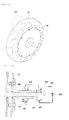
- FIG. 1 is a side cross-sectional view showing an embodiment of the inside of a tire and a hydraulic driving apparatus of a power generator using load applied to a tire according to the present invention
- FIG. 2 is a front cross-sectional view showing an embodiment of the inside of the hydraulic driving apparatus and an electric generator of the power generator using load applied to a tire according to the present invention
- FIG. 3 is a perspective view showing an embodiment of a diaphragm formed perpendicular to the moving direction of a tire in a compartment structure of a power generator using load applied to a tire of the related art.
- the present invention is largely composed of a tire 10, hydraulic hoses transmitting hydraulic pressure, a hydraulic driving apparatus 200 that is mounted inside a wheel 20 and generates torque, using the hydraulic pressure, an electric generator 300 that generates electricity, using the torque, and an electricity-leading unit.
- diaphragms 110 are formed diagonally to the moving direction of the tire in the tire 10 and compartments 120 that separately house fluid are defined between the diaphragms 110.
- hydraulic ejection hoses 130 for ejecting fluid from the inside of the compartments 120 into the hydraulic driving apparatus 200 and hydraulic suction hoses 140 for sucking the fluid from the hydraulic driving apparatus 200 into the compartments are mounted in this structure, in which the hydraulic hoses are connected to the wheel 20 for the compartments and a housing 210 of the hydraulic driving apparatus 210.
- the hydraulic driving apparatus 200 is fixed inside the wheel 20 and includes a housing 210 fixed to the electric generator 300 and a driving gear 220 generating torque while rotating opposite to the tire by means of fluid ejected from the hydraulic ejection hoses 130 at the center in the housing 210, in which a driving shaft 230 extends from the center of the driving gear to transmit the torque from the driving gear to the electric generator 300 and driven gears 240 are engaged with the driving gear 220 to efficiently transmit force from the fluid.
- the connecting portion with the wheel of the hydraulic hose 130 shown in FIG. 2 is positioned at the center portion of the outer circumference of the wheel, but this is for convenience in understanding, and it is preferable to move the connecting portion to the left in the figure in consideration of interference in flow of fluid in actual manufacturing and it is preferable that the hydraulic hose is made of a flexible material.
- the electric generator is mounted inside the wheel 20 while separating from the axle and includes an electric generator housing 310 fixed to the wheel 20 and a field coil 320 fixed to the housing and generating electric force while rotating in the same direction as the tire, in which a rotator 330 generating electricity while rotating in the opposite direction to the tire by means of the driving shaft 230 is positioned at the center of the housing 310.
- the compartments, hydraulic hoses, and hydraulic driving apparatus 200 are filled with an appropriate amount of fluid and the tire 10 is rotated in the direction A, with load applied from the chassis" the first compartment 120a, the second compartment 120b, and the third compartment 120 are sequentially and temporarily compressed by the vehicle load and then restored.
- the fluid in the second compartment 120b which is compressed, is ejected between the driving gear 220 and the driven gears 240, which are engaged with each other, through the hydraulic ejection hose 130b having a check valve function ejecting fluid only toward the hydraulic driving apparatus 200, while the first compartment 120a, which is restored, sucks some of the fluid from the hydraulic driving apparatus 200 through the hydraulic suction hose 140a having a check valve function, which ejects fluid only toward the compartment 120, by the increased pressure inside the hydraulic driving apparatus 200 and the pressure inside the first compartment 120 which is decreased by restoration of the tire.
- the driving gear and the drive gears rotate and the driving shaft 230 fitted in the center of the driving gear by a key rotate, and accordingly, the rotator of the electric generator rotates opposite to the rotational direction of the electric generator housing 310 fastened to the wheel 20, thereby generating electricity.
- the kinetic energy for rotation of the driving gear 220 is converted from gravity energy applied to the fluid in the compartments by the vehicle load, as described above; therefore, according to the present invention, it is possible to generate electricity while sequentially converting the gravity energy into kinetic energy and the kinetic energy and electric energy, without additionally consuming energy for driving the vehicle.
- gear pump type is applied to the hydraulic driving apparatus 200 in the present invention
- other types known in the art such as a turbine type and a vein type, may be used; however, it is preferable to manufacture the driving gear and the driven gears in a size as similar as possible in terms of transmission of the force from the fluid, when using the gear pump type.
- the hydraulic driving apparatus 200 and the electric generator 300 disposed inside the wheel 20 are separated by the housings 210, 310.
- This is for rotating the rotator 330 only by separating the fluid from the driving gear 220 rotating opposite to the rotational direction of the wheel 20 by means of the fluid in separate housings and extending the driving shaft 230, because the rotational direction of the fluid is opposite to the rotational direction of the field coil 320 when the fluid flows into the electric generator 330 and this may interfere with the rotation of the wheel 20.
- the field coil 320 and the rotator 330 can smoothly rotate in the opposite directions, without friction, in the electric generator 300.
- the housing 210 of the hydraulic driving apparatus, the electric generator housing 310, and the field coil 320 rotate about the axle 340 extending from the wheel 20 in the same direction as the tire 10, whereas the driving gear 220 and the driven gears 330 rotate about the driving shaft 230 in the opposite direction to the tire 10; therefore, it is possible to achieve high electromotive force with magnetic flux change faster than common electric generators composed of a stator and a rotator rotating inside the stator.
- a means for minimize friction and keep hermetic such as an hermetic bearing, may be disposed at predetermined positions such that the driving gear 220 and the driven gears 240, the driving shaft 230 and the housing 210 of the hydraulic driving apparatus, and the electric generator housing 310 and the field coil 320 and the rotator 330 can smoothly rotate in the opposite directions, respectively.
- compartment 120 separates the fluid by using the inner wall of the tire, the diaphragms 110, and the outer wall of the wheel, as shown in FIGS. 1 and 2 , connecting portions between the hydraulic ejection hoses and the hydraulic suction hoses are made of a hermetic material, instead of the diaphragm 110, and a plurality of tubes having the shape of the compartment 120 and filled with fluid may be disposed to be used as the compartments.
- the outer structure of the tube-shaped compartment may be constructed by connection points at the center of the width of the diaphragms 110 formed horizontally or diagonally to the moving direction of the tire, connection points on the outer circumference of the wheel 20, and connection points on the inner wall of the tire.
- the tube-shaped compartment has the advantage of preventing the tire from being damaged due to the diaphragm and relatively simply keeping the compartment hermetic, as compared with the compartment defined by the diaphragms 110.
- FIG. 5 is a side cross-sectional view showing an embodiment of an electricity-leading unit and a field coil grounding unit of the power generator using load applied to a tire according to the present invention.
- an electricity-leading means 400 may be fitted on the outer circumference of the extending portion of the driving shaft, as described above. Further, some of the led electricity can be supplied for the exciting current of the field coil, and for this configuration, other than various types of grounding known in the art, it may be possible to fitting a field coil grounding unit 500 on the outer circumference of the axle 340.
- the field coil grounding unit 500 covers the outer circumference of the axle 340 extending from the wheel 20, while the electricity-leading unit 400 covers the outer circumference of the driving shaft 230 extending outward through the hole 314 of the axle from the driving gear 220.
- a lead wire of the field coil 320 may be embedded between the outer circumference and the inner circumference of the axle 340 and connected with the field coil grounding unit 500, and a coil lead wire of the rotator 330 may be embedded in the driving shaft 230 and connected with the electricity-leading unit 400.
- the electricity-generating unit 400 and the field coil grounding unit 500 have a configuration for maintaining a contact point from the rotator, which is described below.
- FIG. 6 is a side cross-sectional view showing an embodiment of an electricity-leading unit for leading direct current and a field coil grounding unit of the power generator using load applied to a tire according to the present invention. Since the current led by the electric generator 300 is alternating current, the electricity-leading unit 400 converts and leads the alternating current into direct current and the field coil grounding unit 500 supplies the exciting current converted into the direct current to the field coil. It is preferable that an axle 340 having a hole 341 through the center is formed and the driving shaft 230 extends outward while passing through the wheel 20 and the axle 340 such that the driving shaft 230 can pass through the center of the wheel 20 in order to convert the alternating current into direct current and lead electricity according to the present invention, as described in the figures.
- the electricity-leading unit 400 further includes a housing 410 fixed to the chassis, a terminal 430 formed on the outer circumference of the housing 410 to lead electricity, a rectifier 421 fixed to the driving shaft 230 in the housing 410, and an electricity-leading portion 420 formed of a brush 422 connected with the terminal 430 and grounded to the rectifier 421.
- the field coil grounding unit 500 for supplying exciting current to the field coil includes a housing 510 fixed to the chassis while covering the outer circumference of the axle 340, a terminal 530 formed on the outer circumference of the housing 510 to supply exciting current, a slip ring 521 fixed to the axle 340 in the housing 510, and a grounding portion 520 formed of a brush 522 connected to the terminal 530 and grounded to the slip ring 521.
- the alternating current is converted into direct current by the rectifier 421 and the brush 422 of the electricity-leading unit 400, the converted direct current is transmitted to a capacitor or other devices, and some of the direct current can be supplied as direct exciting current to the field coil by the slip ring 521 and the brush 522 of the field coil grounding unit 500.
- FIG. 7 is a side cross-sectional view showing an embodiment of an electricity-leading unit for leading alternating current and a field coil grounding unit of the power generator using load applied to a tire according to the present invention.
- the axle 340 having the hole 341 through the center such that the driving shaft 230 can pass is disposed in the center of the wheel 20, the driving shaft 230 extends outward through the wheel 20 and the axle 340, and the electricity-leading unit 400 further includes the housing 410 fixed to the chassis, the terminal 430 formed on the outer circumference of the housing 410 to lead electricity, a slip ring 423 fixed to the driving shaft 230 in the housing 410, and a brush 424 connected to the terminal 430 and grounded to the slip ring 423.
- the field coil grounding unit is composed of the housing 510 fixed to the chassis while covering the outer circumference of the axle 340, the terminal 530 formed on the outer circumference of the housing 510 to supply exciting current, the rectifier 523 fixed to the axle 340 in the housing 510, and the brush 524 connected to with the terminal 530 and grounded to the rectifier 523.
- the present invention can be used for all transportation driven by common tires, and can be used for, in addition to common vehicle, specific vehicles, such as electric vehicles, hybrid vehicles, container vehicles, forklift trucks, shovelers, and bulldozers, and tractors, electric carriers, golf cars, and electric bicycles, such that the industrial applicability is very high.
- specific vehicles such as electric vehicles, hybrid vehicles, container vehicles, forklift trucks, shovelers, and bulldozers, and tractors, electric carriers, golf cars, and electric bicycles, such that the industrial applicability is very high.
Landscapes
- Engineering & Computer Science (AREA)
- Chemical & Material Sciences (AREA)
- Combustion & Propulsion (AREA)
- Mechanical Engineering (AREA)
- General Engineering & Computer Science (AREA)
- Power Engineering (AREA)
- Transportation (AREA)
- Connection Of Motors, Electrical Generators, Mechanical Devices, And The Like (AREA)
- Arrangement Or Mounting Of Propulsion Units For Vehicles (AREA)
- Dc Machiner (AREA)
Applications Claiming Priority (2)
| Application Number | Priority Date | Filing Date | Title |
|---|---|---|---|
| KR20080035845 | 2008-04-18 | ||
| PCT/KR2009/002050 WO2009128690A2 (fr) | 2008-04-18 | 2009-04-20 | Générateur d'énergie exploitant une charge appliquée sur un pneu |
Publications (1)
| Publication Number | Publication Date |
|---|---|
| EP2284036A2 true EP2284036A2 (fr) | 2011-02-16 |
Family
ID=41199604
Family Applications (1)
| Application Number | Title | Priority Date | Filing Date |
|---|---|---|---|
| EP09733527A Withdrawn EP2284036A2 (fr) | 2008-04-18 | 2009-04-20 | Générateur d'énergie exploitant une charge appliquée sur un pneu |
Country Status (5)
| Country | Link |
|---|---|
| US (1) | US20110042966A1 (fr) |
| EP (1) | EP2284036A2 (fr) |
| JP (1) | JP2011522986A (fr) |
| CN (1) | CN102007015A (fr) |
| WO (1) | WO2009128690A2 (fr) |
Families Citing this family (10)
| Publication number | Priority date | Publication date | Assignee | Title |
|---|---|---|---|---|
| KR101394552B1 (ko) * | 2013-07-05 | 2014-05-16 | 윤주학 | 풍력 발전장치 |
| CN104454401B (zh) * | 2014-05-27 | 2018-08-03 | 湖南华园科技有限公司 | 一种新能源重力发电机 |
| US20160114681A1 (en) * | 2014-10-27 | 2016-04-28 | Chin-Yuan Chung | Structure Of Generator Of Motor Vehicle |
| KR101672612B1 (ko) * | 2015-01-09 | 2016-11-03 | 박계정 | 타이어 변형을 이용한 발전시스템 |
| KR101980156B1 (ko) * | 2017-03-21 | 2019-05-20 | 김호남 | 자동차용 자가발전장치 및 연료절감장치 |
| WO2018190515A1 (fr) * | 2017-04-12 | 2018-10-18 | 김호남 | Dispositif de production d'énergie indépendant de véhicule et dispositif d'économie de carburant |
| JP7462896B2 (ja) * | 2019-10-09 | 2024-04-08 | 国立大学法人 東京大学 | 無線受電システム、移動体、及び車輪 |
| CN111674218B (zh) * | 2020-05-26 | 2025-03-25 | 淮阴工学院 | 一种汽车圆周式电磁馈能液力作动器装置 |
| CN112572146A (zh) * | 2020-11-17 | 2021-03-30 | 蔡梦雄 | 一种基于车轮行进的能量收集系统 |
| IL283984B2 (en) * | 2021-06-14 | 2025-03-01 | Margolis Alex | A device that drives continuous production of electricity |
Family Cites Families (17)
| Publication number | Priority date | Publication date | Assignee | Title |
|---|---|---|---|---|
| JPS4876018A (fr) * | 1972-01-13 | 1973-10-13 | ||
| US4061200A (en) * | 1976-01-12 | 1977-12-06 | Thompson Joseph A | Vehicular energy generation system |
| US4405872A (en) * | 1978-09-07 | 1983-09-20 | Thomas Stephen E | Method and apparatus for generating electrical energy from the rotation of a wheel |
| JPS5675978A (en) * | 1979-11-27 | 1981-06-23 | Kunio Harada | Power generating method by utilizing rotation of tire |
| JPH0746057Y2 (ja) * | 1986-08-30 | 1995-10-18 | 株式会社東海理化電機製作所 | 発電装置 |
| US6291901B1 (en) * | 2000-06-13 | 2001-09-18 | ćEFO NEVRES | Electrical power generating tire system |
| KR20020059284A (ko) * | 2002-05-30 | 2002-07-12 | 김재석 | 타이어에 가해지는 차체의 하중을 이용한 동력발생장치 |
| US6744356B2 (en) * | 2002-07-11 | 2004-06-01 | Autoliv Asp, Inc. | Tire pressure maintenance and monitoring system |
| JP3720316B2 (ja) * | 2002-09-24 | 2005-11-24 | 独立行政法人科学技術振興機構 | 電気自動車の駆動装置 |
| US6809426B2 (en) * | 2003-01-06 | 2004-10-26 | Claude A. Naar | Gravity-based vehicle power system |
| US7009310B2 (en) * | 2004-01-12 | 2006-03-07 | Rockwell Scientific Licensing, Llc | Autonomous power source |
| KR20040080420A (ko) * | 2004-08-30 | 2004-09-18 | 장광호 | 유압으로 구동되는 자동차 |
| WO2006074606A1 (fr) * | 2005-01-12 | 2006-07-20 | Jiangbin Zhu | Dispositif generateur electrique d'une roue d'un vehicule |
| JP4634321B2 (ja) * | 2006-02-28 | 2011-02-16 | 日立オートモティブシステムズ株式会社 | 電動4輪駆動車用制御装置 |
| JP2008044588A (ja) * | 2006-08-18 | 2008-02-28 | Junichi Yoshimori | 二輪車のハイブリット機能を可能にした発電機兼用駆動モーター |
| US7687943B2 (en) * | 2006-10-19 | 2010-03-30 | Doug Lunde | Electricity generating wheel system |
| EP2065228B1 (fr) * | 2007-11-27 | 2013-04-10 | Infineon Technologies AG | Système et procédé d'exploitation d'énergie |
-
2009
- 2009-04-20 EP EP09733527A patent/EP2284036A2/fr not_active Withdrawn
- 2009-04-20 WO PCT/KR2009/002050 patent/WO2009128690A2/fr not_active Ceased
- 2009-04-20 JP JP2011504935A patent/JP2011522986A/ja active Pending
- 2009-04-20 US US12/988,322 patent/US20110042966A1/en not_active Abandoned
- 2009-04-20 CN CN2009801136078A patent/CN102007015A/zh active Pending
Non-Patent Citations (1)
| Title |
|---|
| See references of WO2009128690A2 * |
Also Published As
| Publication number | Publication date |
|---|---|
| WO2009128690A2 (fr) | 2009-10-22 |
| US20110042966A1 (en) | 2011-02-24 |
| WO2009128690A3 (fr) | 2010-02-18 |
| JP2011522986A (ja) | 2011-08-04 |
| CN102007015A (zh) | 2011-04-06 |
Similar Documents
| Publication | Publication Date | Title |
|---|---|---|
| US20110042966A1 (en) | Power generator using load applied to tire | |
| US9457671B2 (en) | Drive system for a motor vehicle | |
| US8072182B2 (en) | Hybrid automotive vehicle with closed-circuit, inductance battery charging | |
| CN101331031B (zh) | 转向控制装置以及电动车辆 | |
| CN102826003B (zh) | 轮内驱动装置 | |
| AU2007219849B2 (en) | Securing structure of stator and electric vehicle | |
| US20100108416A1 (en) | Direct current drive land vehicle | |
| CN101682242A (zh) | 流体动力式发电机 | |
| WO2010071540A1 (fr) | Véhicule à moteur électrique, kit de production d'un véhicule à moteur électrique, et procédé de production de véhicule à moteur électrique | |
| CN101466565B (zh) | 车辆驱动机构 | |
| US20100155161A1 (en) | Turbine-based power-generating system for hybrid and electric automobiles, cars, transports, machinery and motorcycles | |
| KR20110047902A (ko) | 타이어에 가해지는 하중을 이용한 발전장치 | |
| JP2010000859A (ja) | ハイブリッド電気自動車の駆動装置 | |
| CN104600905A (zh) | 一种一体化减速轮毂电机 | |
| US20230253859A1 (en) | Retractable and detachable wheel-based tire generator type range extender and recharger for electric vehicles | |
| US10090734B2 (en) | Electricity generation system using tire deformation | |
| CN202243039U (zh) | 一种多能源电动车 | |
| US20080111519A1 (en) | Hybrid automotive vehicle with closed-circuit battery charging | |
| CN101277043B (zh) | 一种混合动力车用变频调速电机及发电机组 | |
| CN201038901Y (zh) | 一种混合动力车用变频调速电机及发电机组 | |
| KR20120098371A (ko) | 차량의 무게를 이용한 동력발생장치 | |
| US20080110485A1 (en) | Hybrid automotive vehicle with solar battery charging | |
| KR20020059284A (ko) | 타이어에 가해지는 차체의 하중을 이용한 동력발생장치 | |
| US20120049675A1 (en) | Electric power generating differential | |
| KR20190116156A (ko) | 매그너스 효과를 이용하는 자가 발전형 모터 |
Legal Events
| Date | Code | Title | Description |
|---|---|---|---|
| PUAI | Public reference made under article 153(3) epc to a published international application that has entered the european phase |
Free format text: ORIGINAL CODE: 0009012 |
|
| 17P | Request for examination filed |
Effective date: 20101118 |
|
| AK | Designated contracting states |
Kind code of ref document: A2 Designated state(s): AT BE BG CH CY CZ DE DK EE ES FI FR GB GR HR HU IE IS IT LI LT LU LV MC MK MT NL NO PL PT RO SE SI SK TR |
|
| AX | Request for extension of the european patent |
Extension state: AL BA RS |
|
| DAX | Request for extension of the european patent (deleted) | ||
| STAA | Information on the status of an ep patent application or granted ep patent |
Free format text: STATUS: THE APPLICATION IS DEEMED TO BE WITHDRAWN |
|
| 18D | Application deemed to be withdrawn |
Effective date: 20131101 |