EP2284140A2 - Procédé de fabrication de revêtements de barrière environnementale à base de solvants utilisant des supports de frittage - Google Patents
Procédé de fabrication de revêtements de barrière environnementale à base de solvants utilisant des supports de frittage Download PDFInfo
- Publication number
- EP2284140A2 EP2284140A2 EP10171503A EP10171503A EP2284140A2 EP 2284140 A2 EP2284140 A2 EP 2284140A2 EP 10171503 A EP10171503 A EP 10171503A EP 10171503 A EP10171503 A EP 10171503A EP 2284140 A2 EP2284140 A2 EP 2284140A2
- Authority
- EP
- European Patent Office
- Prior art keywords
- layer
- slurry
- transition
- compliant
- sintering
- Prior art date
- Legal status (The legal status is an assumption and is not a legal conclusion. Google has not performed a legal analysis and makes no representation as to the accuracy of the status listed.)
- Withdrawn
Links
- 238000005245 sintering Methods 0.000 title claims abstract description 170
- 238000000034 method Methods 0.000 title claims abstract description 84
- 239000002904 solvent Substances 0.000 title claims abstract description 80
- 238000000576 coating method Methods 0.000 title claims abstract description 63
- 230000004888 barrier function Effects 0.000 title claims abstract description 41
- 230000007613 environmental effect Effects 0.000 title claims abstract description 38
- 239000002002 slurry Substances 0.000 claims abstract description 215
- 230000007704 transition Effects 0.000 claims abstract description 202
- 239000000463 material Substances 0.000 claims abstract description 141
- 229910052761 rare earth metal Inorganic materials 0.000 claims abstract description 87
- 150000002910 rare earth metals Chemical class 0.000 claims abstract description 67
- 239000011248 coating agent Substances 0.000 claims abstract description 53
- XLYOFNOQVPJJNP-UHFFFAOYSA-N water Substances O XLYOFNOQVPJJNP-UHFFFAOYSA-N 0.000 claims abstract description 44
- 150000003839 salts Chemical class 0.000 claims abstract description 40
- 239000003960 organic solvent Substances 0.000 claims abstract description 35
- 239000000243 solution Substances 0.000 claims abstract description 23
- 238000006243 chemical reaction Methods 0.000 claims abstract description 9
- 239000007864 aqueous solution Substances 0.000 claims abstract description 8
- 230000008439 repair process Effects 0.000 claims description 47
- 230000007547 defect Effects 0.000 claims description 39
- 239000000919 ceramic Substances 0.000 claims description 29
- 239000006057 Non-nutritive feed additive Substances 0.000 claims description 28
- 239000000203 mixture Substances 0.000 claims description 27
- LFQSCWFLJHTTHZ-UHFFFAOYSA-N Ethanol Chemical compound CCO LFQSCWFLJHTTHZ-UHFFFAOYSA-N 0.000 claims description 22
- ZWEHNKRNPOVVGH-UHFFFAOYSA-N 2-Butanone Chemical compound CCC(C)=O ZWEHNKRNPOVVGH-UHFFFAOYSA-N 0.000 claims description 18
- CSCPPACGZOOCGX-UHFFFAOYSA-N Acetone Chemical compound CC(C)=O CSCPPACGZOOCGX-UHFFFAOYSA-N 0.000 claims description 15
- OKKJLVBELUTLKV-UHFFFAOYSA-N Methanol Chemical compound OC OKKJLVBELUTLKV-UHFFFAOYSA-N 0.000 claims description 15
- YXFVVABEGXRONW-UHFFFAOYSA-N Toluene Chemical compound CC1=CC=CC=C1 YXFVVABEGXRONW-UHFFFAOYSA-N 0.000 claims description 15
- 238000011068 loading method Methods 0.000 claims description 14
- 239000007787 solid Substances 0.000 claims description 14
- 239000011153 ceramic matrix composite Substances 0.000 claims description 12
- 159000000014 iron salts Chemical class 0.000 claims description 11
- KBPLFHHGFOOTCA-UHFFFAOYSA-N 1-Octanol Chemical compound CCCCCCCCO KBPLFHHGFOOTCA-UHFFFAOYSA-N 0.000 claims description 10
- BBMCTIGTTCKYKF-UHFFFAOYSA-N 1-heptanol Chemical compound CCCCCCCO BBMCTIGTTCKYKF-UHFFFAOYSA-N 0.000 claims description 10
- YNQLUTRBYVCPMQ-UHFFFAOYSA-N Ethylbenzene Chemical compound CCC1=CC=CC=C1 YNQLUTRBYVCPMQ-UHFFFAOYSA-N 0.000 claims description 10
- LRHPLDYGYMQRHN-UHFFFAOYSA-N N-Butanol Chemical compound CCCCO LRHPLDYGYMQRHN-UHFFFAOYSA-N 0.000 claims description 10
- IMNFDUFMRHMDMM-UHFFFAOYSA-N N-Heptane Chemical compound CCCCCCC IMNFDUFMRHMDMM-UHFFFAOYSA-N 0.000 claims description 10
- AMQJEAYHLZJPGS-UHFFFAOYSA-N N-Pentanol Chemical compound CCCCCO AMQJEAYHLZJPGS-UHFFFAOYSA-N 0.000 claims description 10
- WYURNTSHIVDZCO-UHFFFAOYSA-N Tetrahydrofuran Chemical compound C1CCOC1 WYURNTSHIVDZCO-UHFFFAOYSA-N 0.000 claims description 10
- RDOXTESZEPMUJZ-UHFFFAOYSA-N anisole Chemical compound COC1=CC=CC=C1 RDOXTESZEPMUJZ-UHFFFAOYSA-N 0.000 claims description 10
- MWKFXSUHUHTGQN-UHFFFAOYSA-N decan-1-ol Chemical compound CCCCCCCCCCO MWKFXSUHUHTGQN-UHFFFAOYSA-N 0.000 claims description 10
- DIOQZVSQGTUSAI-UHFFFAOYSA-N decane Chemical compound CCCCCCCCCC DIOQZVSQGTUSAI-UHFFFAOYSA-N 0.000 claims description 10
- LQZZUXJYWNFBMV-UHFFFAOYSA-N dodecan-1-ol Chemical compound CCCCCCCCCCCCO LQZZUXJYWNFBMV-UHFFFAOYSA-N 0.000 claims description 10
- ZSIAUFGUXNUGDI-UHFFFAOYSA-N hexan-1-ol Chemical compound CCCCCCO ZSIAUFGUXNUGDI-UHFFFAOYSA-N 0.000 claims description 10
- ZWRUINPWMLAQRD-UHFFFAOYSA-N nonan-1-ol Chemical compound CCCCCCCCCO ZWRUINPWMLAQRD-UHFFFAOYSA-N 0.000 claims description 10
- BKIMMITUMNQMOS-UHFFFAOYSA-N nonane Chemical compound CCCCCCCCC BKIMMITUMNQMOS-UHFFFAOYSA-N 0.000 claims description 10
- ODLMAHJVESYWTB-UHFFFAOYSA-N propylbenzene Chemical compound CCCC1=CC=CC=C1 ODLMAHJVESYWTB-UHFFFAOYSA-N 0.000 claims description 10
- AZDRQVAHHNSJOQ-UHFFFAOYSA-N alumane Chemical class [AlH3] AZDRQVAHHNSJOQ-UHFFFAOYSA-N 0.000 claims description 9
- 150000001638 boron Chemical class 0.000 claims description 9
- 150000002258 gallium Chemical class 0.000 claims description 9
- 150000002815 nickel Chemical class 0.000 claims description 9
- 150000003608 titanium Chemical class 0.000 claims description 9
- NTIZESTWPVYFNL-UHFFFAOYSA-N Methyl isobutyl ketone Chemical compound CC(C)CC(C)=O NTIZESTWPVYFNL-UHFFFAOYSA-N 0.000 claims description 6
- UIHCLUNTQKBZGK-UHFFFAOYSA-N Methyl isobutyl ketone Natural products CCC(C)C(C)=O UIHCLUNTQKBZGK-UHFFFAOYSA-N 0.000 claims description 6
- CTQNGGLPUBDAKN-UHFFFAOYSA-N O-Xylene Chemical compound CC1=CC=CC=C1C CTQNGGLPUBDAKN-UHFFFAOYSA-N 0.000 claims description 5
- 150000002170 ethers Chemical class 0.000 claims description 5
- 229910052500 inorganic mineral Inorganic materials 0.000 claims description 5
- UZKWTJUDCOPSNM-UHFFFAOYSA-N methoxybenzene Substances CCCCOC=C UZKWTJUDCOPSNM-UHFFFAOYSA-N 0.000 claims description 5
- 239000011707 mineral Substances 0.000 claims description 5
- TVMXDCGIABBOFY-UHFFFAOYSA-N octane Chemical compound CCCCCCCC TVMXDCGIABBOFY-UHFFFAOYSA-N 0.000 claims description 5
- BDERNNFJNOPAEC-UHFFFAOYSA-N propan-1-ol Chemical compound CCCO BDERNNFJNOPAEC-UHFFFAOYSA-N 0.000 claims description 5
- 235000015096 spirit Nutrition 0.000 claims description 5
- YLQBMQCUIZJEEH-UHFFFAOYSA-N tetrahydrofuran Natural products C=1C=COC=1 YLQBMQCUIZJEEH-UHFFFAOYSA-N 0.000 claims description 5
- 239000008096 xylene Substances 0.000 claims description 5
- 239000010410 layer Substances 0.000 description 381
- VYPSYNLAJGMNEJ-UHFFFAOYSA-N Silicium dioxide Chemical compound O=[Si]=O VYPSYNLAJGMNEJ-UHFFFAOYSA-N 0.000 description 59
- -1 CrSi3) Inorganic materials 0.000 description 51
- 239000000377 silicon dioxide Substances 0.000 description 28
- MCMNRKCIXSYSNV-UHFFFAOYSA-N Zirconium dioxide Chemical compound O=[Zr]=O MCMNRKCIXSYSNV-UHFFFAOYSA-N 0.000 description 20
- 238000001035 drying Methods 0.000 description 20
- 238000010438 heat treatment Methods 0.000 description 19
- XEEYBQQBJWHFJM-UHFFFAOYSA-N Iron Chemical compound [Fe] XEEYBQQBJWHFJM-UHFFFAOYSA-N 0.000 description 18
- PXHVJJICTQNCMI-UHFFFAOYSA-N Nickel Chemical compound [Ni] PXHVJJICTQNCMI-UHFFFAOYSA-N 0.000 description 18
- 238000002156 mixing Methods 0.000 description 15
- 229910052710 silicon Inorganic materials 0.000 description 13
- 239000010703 silicon Substances 0.000 description 13
- XUIMIQQOPSSXEZ-UHFFFAOYSA-N Silicon Chemical compound [Si] XUIMIQQOPSSXEZ-UHFFFAOYSA-N 0.000 description 11
- 150000001875 compounds Chemical class 0.000 description 10
- 229910052733 gallium Inorganic materials 0.000 description 10
- UQSXHKLRYXJYBZ-UHFFFAOYSA-N iron oxide Inorganic materials [Fe]=O UQSXHKLRYXJYBZ-UHFFFAOYSA-N 0.000 description 10
- 229910052759 nickel Inorganic materials 0.000 description 10
- 230000008569 process Effects 0.000 description 10
- FIIGRZYDBNZZFN-UHFFFAOYSA-N trioxido(trioxidosilyloxy)silane ytterbium(3+) Chemical compound [Si]([O-])([O-])([O-])O[Si]([O-])([O-])[O-].[Yb+3].[Yb+3] FIIGRZYDBNZZFN-UHFFFAOYSA-N 0.000 description 10
- LYCAIKOWRPUZTN-UHFFFAOYSA-N Ethylene glycol Chemical compound OCCO LYCAIKOWRPUZTN-UHFFFAOYSA-N 0.000 description 9
- 239000002270 dispersing agent Substances 0.000 description 9
- GYHNNYVSQQEPJS-UHFFFAOYSA-N Gallium Chemical compound [Ga] GYHNNYVSQQEPJS-UHFFFAOYSA-N 0.000 description 8
- 229910052782 aluminium Inorganic materials 0.000 description 8
- 239000007789 gas Substances 0.000 description 8
- 229910052742 iron Inorganic materials 0.000 description 8
- 239000002245 particle Substances 0.000 description 8
- 239000002562 thickening agent Substances 0.000 description 8
- 229920002873 Polyethylenimine Polymers 0.000 description 7
- GWEVSGVZZGPLCZ-UHFFFAOYSA-N Titan oxide Chemical compound O=[Ti]=O GWEVSGVZZGPLCZ-UHFFFAOYSA-N 0.000 description 7
- 239000003570 air Substances 0.000 description 7
- XAGFODPZIPBFFR-UHFFFAOYSA-N aluminium Chemical compound [Al] XAGFODPZIPBFFR-UHFFFAOYSA-N 0.000 description 7
- PNEYBMLMFCGWSK-UHFFFAOYSA-N aluminium oxide Inorganic materials [O-2].[O-2].[O-2].[Al+3].[Al+3] PNEYBMLMFCGWSK-UHFFFAOYSA-N 0.000 description 7
- 229910052681 coesite Inorganic materials 0.000 description 7
- 229910052906 cristobalite Inorganic materials 0.000 description 7
- 230000000873 masking effect Effects 0.000 description 7
- 229910010271 silicon carbide Inorganic materials 0.000 description 7
- 229910052682 stishovite Inorganic materials 0.000 description 7
- 239000004094 surface-active agent Substances 0.000 description 7
- 239000010936 titanium Substances 0.000 description 7
- 229910052905 tridymite Inorganic materials 0.000 description 7
- 238000007796 conventional method Methods 0.000 description 6
- 238000000151 deposition Methods 0.000 description 6
- 235000013980 iron oxide Nutrition 0.000 description 6
- 239000004014 plasticizer Substances 0.000 description 6
- 239000007921 spray Substances 0.000 description 6
- 229910052796 boron Inorganic materials 0.000 description 5
- 230000008021 deposition Effects 0.000 description 5
- 230000008595 infiltration Effects 0.000 description 5
- 238000001764 infiltration Methods 0.000 description 5
- 229910052751 metal Inorganic materials 0.000 description 5
- 239000002184 metal Substances 0.000 description 5
- 229910021332 silicide Inorganic materials 0.000 description 5
- 230000003746 surface roughness Effects 0.000 description 5
- 229910052719 titanium Inorganic materials 0.000 description 5
- NBIIXXVUZAFLBC-UHFFFAOYSA-N Phosphoric acid Chemical compound OP(O)(O)=O NBIIXXVUZAFLBC-UHFFFAOYSA-N 0.000 description 4
- XQWQNVHACLGSBB-UHFFFAOYSA-N [Si]([O-])([O-])([O-])O.[Yb+3] Chemical compound [Si]([O-])([O-])([O-])O.[Yb+3] XQWQNVHACLGSBB-UHFFFAOYSA-N 0.000 description 4
- 239000003513 alkali Substances 0.000 description 4
- 229910052593 corundum Inorganic materials 0.000 description 4
- 238000007598 dipping method Methods 0.000 description 4
- 229910001404 rare earth metal oxide Inorganic materials 0.000 description 4
- 150000004760 silicates Chemical class 0.000 description 4
- FVBUAEGBCNSCDD-UHFFFAOYSA-N silicide(4-) Chemical compound [Si-4] FVBUAEGBCNSCDD-UHFFFAOYSA-N 0.000 description 4
- 229910001845 yogo sapphire Inorganic materials 0.000 description 4
- ZOXJGFHDIHLPTG-UHFFFAOYSA-N Boron Chemical compound [B] ZOXJGFHDIHLPTG-UHFFFAOYSA-N 0.000 description 3
- 229910052684 Cerium Inorganic materials 0.000 description 3
- 229910052693 Europium Inorganic materials 0.000 description 3
- 229910052688 Gadolinium Inorganic materials 0.000 description 3
- 229910052779 Neodymium Inorganic materials 0.000 description 3
- 229910052777 Praseodymium Inorganic materials 0.000 description 3
- 229910052773 Promethium Inorganic materials 0.000 description 3
- DNIAPMSPPWPWGF-UHFFFAOYSA-N Propylene glycol Chemical compound CC(O)CO DNIAPMSPPWPWGF-UHFFFAOYSA-N 0.000 description 3
- 229910052772 Samarium Inorganic materials 0.000 description 3
- RTAQQCXQSZGOHL-UHFFFAOYSA-N Titanium Chemical compound [Ti] RTAQQCXQSZGOHL-UHFFFAOYSA-N 0.000 description 3
- 229910052769 Ytterbium Inorganic materials 0.000 description 3
- 239000000853 adhesive Substances 0.000 description 3
- 230000001070 adhesive effect Effects 0.000 description 3
- 229910000323 aluminium silicate Inorganic materials 0.000 description 3
- 230000008901 benefit Effects 0.000 description 3
- 239000011230 binding agent Substances 0.000 description 3
- 239000005388 borosilicate glass Substances 0.000 description 3
- 239000011575 calcium Substances 0.000 description 3
- GWXLDORMOJMVQZ-UHFFFAOYSA-N cerium Chemical compound [Ce] GWXLDORMOJMVQZ-UHFFFAOYSA-N 0.000 description 3
- 238000005229 chemical vapour deposition Methods 0.000 description 3
- 238000005137 deposition process Methods 0.000 description 3
- DOIRQSBPFJWKBE-UHFFFAOYSA-N dibutyl phthalate Chemical compound CCCCOC(=O)C1=CC=CC=C1C(=O)OCCCC DOIRQSBPFJWKBE-UHFFFAOYSA-N 0.000 description 3
- MTHSVFCYNBDYFN-UHFFFAOYSA-N diethylene glycol Chemical compound OCCOCCO MTHSVFCYNBDYFN-UHFFFAOYSA-N 0.000 description 3
- AJNVQOSZGJRYEI-UHFFFAOYSA-N digallium;oxygen(2-) Chemical compound [O-2].[O-2].[O-2].[Ga+3].[Ga+3] AJNVQOSZGJRYEI-UHFFFAOYSA-N 0.000 description 3
- KZHJGOXRZJKJNY-UHFFFAOYSA-N dioxosilane;oxo(oxoalumanyloxy)alumane Chemical compound O=[Si]=O.O=[Si]=O.O=[Al]O[Al]=O.O=[Al]O[Al]=O.O=[Al]O[Al]=O KZHJGOXRZJKJNY-UHFFFAOYSA-N 0.000 description 3
- 238000005328 electron beam physical vapour deposition Methods 0.000 description 3
- OGPBJKLSAFTDLK-UHFFFAOYSA-N europium atom Chemical compound [Eu] OGPBJKLSAFTDLK-UHFFFAOYSA-N 0.000 description 3
- UIWYJDYFSGRHKR-UHFFFAOYSA-N gadolinium atom Chemical compound [Gd] UIWYJDYFSGRHKR-UHFFFAOYSA-N 0.000 description 3
- 229910001195 gallium oxide Inorganic materials 0.000 description 3
- 239000011261 inert gas Substances 0.000 description 3
- 229910052909 inorganic silicate Inorganic materials 0.000 description 3
- 229910052746 lanthanum Inorganic materials 0.000 description 3
- FZLIPJUXYLNCLC-UHFFFAOYSA-N lanthanum atom Chemical compound [La] FZLIPJUXYLNCLC-UHFFFAOYSA-N 0.000 description 3
- 239000011777 magnesium Substances 0.000 description 3
- 239000011159 matrix material Substances 0.000 description 3
- 229910052863 mullite Inorganic materials 0.000 description 3
- QEFYFXOXNSNQGX-UHFFFAOYSA-N neodymium atom Chemical compound [Nd] QEFYFXOXNSNQGX-UHFFFAOYSA-N 0.000 description 3
- 229910000480 nickel oxide Inorganic materials 0.000 description 3
- 239000011368 organic material Substances 0.000 description 3
- 230000003647 oxidation Effects 0.000 description 3
- 238000007254 oxidation reaction Methods 0.000 description 3
- 229920003023 plastic Polymers 0.000 description 3
- 239000004033 plastic Substances 0.000 description 3
- PUDIUYLPXJFUGB-UHFFFAOYSA-N praseodymium atom Chemical compound [Pr] PUDIUYLPXJFUGB-UHFFFAOYSA-N 0.000 description 3
- VQMWBBYLQSCNPO-UHFFFAOYSA-N promethium atom Chemical compound [Pm] VQMWBBYLQSCNPO-UHFFFAOYSA-N 0.000 description 3
- 239000012779 reinforcing material Substances 0.000 description 3
- 238000005096 rolling process Methods 0.000 description 3
- KZUNJOHGWZRPMI-UHFFFAOYSA-N samarium atom Chemical compound [Sm] KZUNJOHGWZRPMI-UHFFFAOYSA-N 0.000 description 3
- 239000011734 sodium Substances 0.000 description 3
- 229910052712 strontium Inorganic materials 0.000 description 3
- CIOAGBVUUVVLOB-UHFFFAOYSA-N strontium atom Chemical compound [Sr] CIOAGBVUUVVLOB-UHFFFAOYSA-N 0.000 description 3
- 229910000601 superalloy Inorganic materials 0.000 description 3
- OGIDPMRJRNCKJF-UHFFFAOYSA-N titanium oxide Inorganic materials [Ti]=O OGIDPMRJRNCKJF-UHFFFAOYSA-N 0.000 description 3
- NAWDYIZEMPQZHO-UHFFFAOYSA-N ytterbium Chemical compound [Yb] NAWDYIZEMPQZHO-UHFFFAOYSA-N 0.000 description 3
- NECRQCBKTGZNMH-UHFFFAOYSA-N 3,5-dimethylhex-1-yn-3-ol Chemical class CC(C)CC(C)(O)C#C NECRQCBKTGZNMH-UHFFFAOYSA-N 0.000 description 2
- XKRFYHLGVUSROY-UHFFFAOYSA-N Argon Chemical compound [Ar] XKRFYHLGVUSROY-UHFFFAOYSA-N 0.000 description 2
- IRIAEXORFWYRCZ-UHFFFAOYSA-N Butylbenzyl phthalate Chemical compound CCCCOC(=O)C1=CC=CC=C1C(=O)OCC1=CC=CC=C1 IRIAEXORFWYRCZ-UHFFFAOYSA-N 0.000 description 2
- KCXZNSGUUQJJTR-UHFFFAOYSA-N Di-n-hexyl phthalate Chemical compound CCCCCCOC(=O)C1=CC=CC=C1C(=O)OCCCCCC KCXZNSGUUQJJTR-UHFFFAOYSA-N 0.000 description 2
- MQIUGAXCHLFZKX-UHFFFAOYSA-N Di-n-octyl phthalate Chemical compound CCCCCCCCOC(=O)C1=CC=CC=C1C(=O)OCCCCCCCC MQIUGAXCHLFZKX-UHFFFAOYSA-N 0.000 description 2
- 229910052692 Dysprosium Inorganic materials 0.000 description 2
- PEDCQBHIVMGVHV-UHFFFAOYSA-N Glycerine Chemical compound OCC(O)CO PEDCQBHIVMGVHV-UHFFFAOYSA-N 0.000 description 2
- DGAQECJNVWCQMB-PUAWFVPOSA-M Ilexoside XXIX Chemical compound C[C@@H]1CC[C@@]2(CC[C@@]3(C(=CC[C@H]4[C@]3(CC[C@@H]5[C@@]4(CC[C@@H](C5(C)C)OS(=O)(=O)[O-])C)C)[C@@H]2[C@]1(C)O)C)C(=O)O[C@H]6[C@@H]([C@H]([C@@H]([C@H](O6)CO)O)O)O.[Na+] DGAQECJNVWCQMB-PUAWFVPOSA-M 0.000 description 2
- WHXSMMKQMYFTQS-UHFFFAOYSA-N Lithium Chemical compound [Li] WHXSMMKQMYFTQS-UHFFFAOYSA-N 0.000 description 2
- 229920003171 Poly (ethylene oxide) Polymers 0.000 description 2
- ZLMJMSJWJFRBEC-UHFFFAOYSA-N Potassium Chemical compound [K] ZLMJMSJWJFRBEC-UHFFFAOYSA-N 0.000 description 2
- 229910052581 Si3N4 Inorganic materials 0.000 description 2
- 229910052771 Terbium Inorganic materials 0.000 description 2
- 238000002441 X-ray diffraction Methods 0.000 description 2
- 229910000147 aluminium phosphate Inorganic materials 0.000 description 2
- 238000000498 ball milling Methods 0.000 description 2
- 229910052788 barium Inorganic materials 0.000 description 2
- DSAJWYNOEDNPEQ-UHFFFAOYSA-N barium atom Chemical compound [Ba] DSAJWYNOEDNPEQ-UHFFFAOYSA-N 0.000 description 2
- 230000015572 biosynthetic process Effects 0.000 description 2
- BJQHLKABXJIVAM-UHFFFAOYSA-N bis(2-ethylhexyl) phthalate Chemical compound CCCCC(CC)COC(=O)C1=CC=CC=C1C(=O)OCC(CC)CCCC BJQHLKABXJIVAM-UHFFFAOYSA-N 0.000 description 2
- ZCCIPPOKBCJFDN-UHFFFAOYSA-N calcium nitrate Chemical compound [Ca+2].[O-][N+]([O-])=O.[O-][N+]([O-])=O ZCCIPPOKBCJFDN-UHFFFAOYSA-N 0.000 description 2
- 150000004649 carbonic acid derivatives Chemical class 0.000 description 2
- 230000015556 catabolic process Effects 0.000 description 2
- 229910010293 ceramic material Inorganic materials 0.000 description 2
- 239000011247 coating layer Substances 0.000 description 2
- 238000002485 combustion reaction Methods 0.000 description 2
- 229920001577 copolymer Polymers 0.000 description 2
- 238000006731 degradation reaction Methods 0.000 description 2
- PPQREHKVAOVYBT-UHFFFAOYSA-H dialuminum;tricarbonate Chemical compound [Al+3].[Al+3].[O-]C([O-])=O.[O-]C([O-])=O.[O-]C([O-])=O PPQREHKVAOVYBT-UHFFFAOYSA-H 0.000 description 2
- JKWMSGQKBLHBQQ-UHFFFAOYSA-N diboron trioxide Chemical compound O=BOB=O JKWMSGQKBLHBQQ-UHFFFAOYSA-N 0.000 description 2
- FLKPEMZONWLCSK-UHFFFAOYSA-N diethyl phthalate Chemical compound CCOC(=O)C1=CC=CC=C1C(=O)OCC FLKPEMZONWLCSK-UHFFFAOYSA-N 0.000 description 2
- 238000009792 diffusion process Methods 0.000 description 2
- MGWAVDBGNNKXQV-UHFFFAOYSA-N diisobutyl phthalate Chemical compound CC(C)COC(=O)C1=CC=CC=C1C(=O)OCC(C)C MGWAVDBGNNKXQV-UHFFFAOYSA-N 0.000 description 2
- KBQHZAAAGSGFKK-UHFFFAOYSA-N dysprosium atom Chemical compound [Dy] KBQHZAAAGSGFKK-UHFFFAOYSA-N 0.000 description 2
- 238000002149 energy-dispersive X-ray emission spectroscopy Methods 0.000 description 2
- CHPZKNULDCNCBW-UHFFFAOYSA-N gallium nitrate Chemical compound [Ga+3].[O-][N+]([O-])=O.[O-][N+]([O-])=O.[O-][N+]([O-])=O CHPZKNULDCNCBW-UHFFFAOYSA-N 0.000 description 2
- 150000004679 hydroxides Chemical class 0.000 description 2
- 239000012535 impurity Substances 0.000 description 2
- JEIPFZHSYJVQDO-UHFFFAOYSA-N iron(III) oxide Inorganic materials O=[Fe]O[Fe]=O JEIPFZHSYJVQDO-UHFFFAOYSA-N 0.000 description 2
- 229910052744 lithium Inorganic materials 0.000 description 2
- 238000004519 manufacturing process Methods 0.000 description 2
- 238000002844 melting Methods 0.000 description 2
- 230000008018 melting Effects 0.000 description 2
- 229940031182 nanoparticles iron oxide Drugs 0.000 description 2
- 230000035515 penetration Effects 0.000 description 2
- 239000012071 phase Substances 0.000 description 2
- 229960005235 piperonyl butoxide Drugs 0.000 description 2
- 239000011591 potassium Substances 0.000 description 2
- 229910052700 potassium Inorganic materials 0.000 description 2
- 239000000843 powder Substances 0.000 description 2
- 238000012545 processing Methods 0.000 description 2
- 230000002035 prolonged effect Effects 0.000 description 2
- KVIKMJYUMZPZFU-UHFFFAOYSA-N propan-2-ol;titanium Chemical compound [Ti].CC(C)O.CC(C)O KVIKMJYUMZPZFU-UHFFFAOYSA-N 0.000 description 2
- 238000001878 scanning electron micrograph Methods 0.000 description 2
- HBMJWWWQQXIZIP-UHFFFAOYSA-N silicon carbide Chemical compound [Si+]#[C-] HBMJWWWQQXIZIP-UHFFFAOYSA-N 0.000 description 2
- HQVNEWCFYHHQES-UHFFFAOYSA-N silicon nitride Chemical compound N12[Si]34N5[Si]62N3[Si]51N64 HQVNEWCFYHHQES-UHFFFAOYSA-N 0.000 description 2
- 229910052708 sodium Inorganic materials 0.000 description 2
- GZCRRIHWUXGPOV-UHFFFAOYSA-N terbium atom Chemical compound [Tb] GZCRRIHWUXGPOV-UHFFFAOYSA-N 0.000 description 2
- VXUYXOFXAQZZMF-UHFFFAOYSA-N titanium(IV) isopropoxide Chemical compound CC(C)O[Ti](OC(C)C)(OC(C)C)OC(C)C VXUYXOFXAQZZMF-UHFFFAOYSA-N 0.000 description 2
- BNGXYYYYKUGPPF-UHFFFAOYSA-M (3-methylphenyl)methyl-triphenylphosphanium;chloride Chemical compound [Cl-].CC1=CC=CC(C[P+](C=2C=CC=CC=2)(C=2C=CC=CC=2)C=2C=CC=CC=2)=C1 BNGXYYYYKUGPPF-UHFFFAOYSA-M 0.000 description 1
- WEAMLHXSIBDPGN-UHFFFAOYSA-N (4-hydroxy-3-methylphenyl) thiocyanate Chemical compound CC1=CC(SC#N)=CC=C1O WEAMLHXSIBDPGN-UHFFFAOYSA-N 0.000 description 1
- NOGBEXBVDOCGDB-NRFIWDAESA-L (z)-4-ethoxy-4-oxobut-2-en-2-olate;propan-2-olate;titanium(4+) Chemical compound [Ti+4].CC(C)[O-].CC(C)[O-].CCOC(=O)\C=C(\C)[O-].CCOC(=O)\C=C(\C)[O-] NOGBEXBVDOCGDB-NRFIWDAESA-L 0.000 description 1
- WKYKXNFEMCNSKN-UHFFFAOYSA-N 1-methoxypropan-1-olate titanium(4+) Chemical compound COC([O-])CC.[Ti+4].COC([O-])CC.COC([O-])CC.COC([O-])CC WKYKXNFEMCNSKN-UHFFFAOYSA-N 0.000 description 1
- SKRNXUGVRFTHNX-UHFFFAOYSA-N 2-[2-[2-(2-hydroxyethoxy)ethoxy]ethoxy]ethanol;propane-1,2,3-triol Chemical compound OCC(O)CO.OCCOCCOCCOCCO SKRNXUGVRFTHNX-UHFFFAOYSA-N 0.000 description 1
- VTYZTWSUUXQSPZ-UHFFFAOYSA-N 2-[bis(2-hydroxyethyl)amino]ethanol;propan-2-ol;titanium Chemical compound [Ti].CC(C)O.CC(C)O.OCCN(CCO)CCO.OCCN(CCO)CCO VTYZTWSUUXQSPZ-UHFFFAOYSA-N 0.000 description 1
- KTXWGMUMDPYXNN-UHFFFAOYSA-N 2-ethylhexan-1-olate;titanium(4+) Chemical compound [Ti+4].CCCCC(CC)C[O-].CCCCC(CC)C[O-].CCCCC(CC)C[O-].CCCCC(CC)C[O-] KTXWGMUMDPYXNN-UHFFFAOYSA-N 0.000 description 1
- RLMZHOIDXMRYMJ-UHFFFAOYSA-J 2-methylphenolate;titanium(4+) Chemical compound [Ti+4].CC1=CC=CC=C1[O-].CC1=CC=CC=C1[O-].CC1=CC=CC=C1[O-].CC1=CC=CC=C1[O-] RLMZHOIDXMRYMJ-UHFFFAOYSA-J 0.000 description 1
- KOAUHLUAUFQHBM-UHFFFAOYSA-M 2-methylprop-2-enoate;propan-2-olate;titanium(4+) Chemical compound [Ti+4].CC(C)[O-].CC(C)[O-].CC(C)[O-].CC(=C)C([O-])=O KOAUHLUAUFQHBM-UHFFFAOYSA-M 0.000 description 1
- QUVMSYUGOKEMPX-UHFFFAOYSA-N 2-methylpropan-1-olate;titanium(4+) Chemical compound [Ti+4].CC(C)C[O-].CC(C)C[O-].CC(C)C[O-].CC(C)C[O-] QUVMSYUGOKEMPX-UHFFFAOYSA-N 0.000 description 1
- SIXWIUJQBBANGK-UHFFFAOYSA-N 4-(4-fluorophenyl)-1h-pyrazol-5-amine Chemical compound N1N=CC(C=2C=CC(F)=CC=2)=C1N SIXWIUJQBBANGK-UHFFFAOYSA-N 0.000 description 1
- RVDLHGSZWAELAU-UHFFFAOYSA-N 5-tert-butylthiophene-2-carbonyl chloride Chemical compound CC(C)(C)C1=CC=C(C(Cl)=O)S1 RVDLHGSZWAELAU-UHFFFAOYSA-N 0.000 description 1
- 239000004254 Ammonium phosphate Substances 0.000 description 1
- 229910016064 BaSi2 Inorganic materials 0.000 description 1
- 241000273930 Brevoortia tyrannus Species 0.000 description 1
- FIPWRIJSWJWJAI-UHFFFAOYSA-N Butyl carbitol 6-propylpiperonyl ether Chemical compound C1=C(CCC)C(COCCOCCOCCCC)=CC2=C1OCO2 FIPWRIJSWJWJAI-UHFFFAOYSA-N 0.000 description 1
- XVKRMWQDAAWGGH-UHFFFAOYSA-N CC([O-])C.CC([O-])C.CC([O-])C.[Ti+3].C(C(=C)C)(=O)OCCOC(CC(=O)C)=O Chemical compound CC([O-])C.CC([O-])C.CC([O-])C.[Ti+3].C(C(=C)C)(=O)OCCOC(CC(=O)C)=O XVKRMWQDAAWGGH-UHFFFAOYSA-N 0.000 description 1
- GPNXLAXVNIASTN-UHFFFAOYSA-N COC([O-])CC.[Ba+2].COC([O-])CC Chemical compound COC([O-])CC.[Ba+2].COC([O-])CC GPNXLAXVNIASTN-UHFFFAOYSA-N 0.000 description 1
- 229910014813 CaC2 Inorganic materials 0.000 description 1
- OYPRJOBELJOOCE-UHFFFAOYSA-N Calcium Chemical compound [Ca] OYPRJOBELJOOCE-UHFFFAOYSA-N 0.000 description 1
- OKTJSMMVPCPJKN-UHFFFAOYSA-N Carbon Chemical compound [C] OKTJSMMVPCPJKN-UHFFFAOYSA-N 0.000 description 1
- BVKZGUZCCUSVTD-UHFFFAOYSA-L Carbonate Chemical compound [O-]C([O-])=O BVKZGUZCCUSVTD-UHFFFAOYSA-L 0.000 description 1
- ZVFDTKUVRCTHQE-UHFFFAOYSA-N Diisodecyl phthalate Chemical compound CC(C)CCCCCCCOC(=O)C1=CC=CC=C1C(=O)OCCCCCCCC(C)C ZVFDTKUVRCTHQE-UHFFFAOYSA-N 0.000 description 1
- 229910052691 Erbium Inorganic materials 0.000 description 1
- 239000001856 Ethyl cellulose Substances 0.000 description 1
- ZZSNKZQZMQGXPY-UHFFFAOYSA-N Ethyl cellulose Chemical compound CCOCC1OC(OC)C(OCC)C(OCC)C1OC1C(O)C(O)C(OC)C(CO)O1 ZZSNKZQZMQGXPY-UHFFFAOYSA-N 0.000 description 1
- 229910052689 Holmium Inorganic materials 0.000 description 1
- FUJCRWPEOMXPAD-UHFFFAOYSA-N Li2O Inorganic materials [Li+].[Li+].[O-2] FUJCRWPEOMXPAD-UHFFFAOYSA-N 0.000 description 1
- 229910052765 Lutetium Inorganic materials 0.000 description 1
- FYYHWMGAXLPEAU-UHFFFAOYSA-N Magnesium Chemical compound [Mg] FYYHWMGAXLPEAU-UHFFFAOYSA-N 0.000 description 1
- 229910020101 MgC2 Inorganic materials 0.000 description 1
- 229910020968 MoSi2 Inorganic materials 0.000 description 1
- 229910016004 MoSi3 Inorganic materials 0.000 description 1
- 229910002651 NO3 Inorganic materials 0.000 description 1
- KKCBUQHMOMHUOY-UHFFFAOYSA-N Na2O Inorganic materials [O-2].[Na+].[Na+] KKCBUQHMOMHUOY-UHFFFAOYSA-N 0.000 description 1
- 229910020044 NbSi2 Inorganic materials 0.000 description 1
- 239000000020 Nitrocellulose Substances 0.000 description 1
- BPQQTUXANYXVAA-UHFFFAOYSA-N Orthosilicate Chemical compound [O-][Si]([O-])([O-])[O-] BPQQTUXANYXVAA-UHFFFAOYSA-N 0.000 description 1
- MUBZPKHOEPUJKR-UHFFFAOYSA-N Oxalic acid Chemical compound OC(=O)C(O)=O MUBZPKHOEPUJKR-UHFFFAOYSA-N 0.000 description 1
- 229920002845 Poly(methacrylic acid) Polymers 0.000 description 1
- 239000002202 Polyethylene glycol Substances 0.000 description 1
- 229920002125 Sokalan® Polymers 0.000 description 1
- 229910003383 SrSiO3 Inorganic materials 0.000 description 1
- 229910004217 TaSi2 Inorganic materials 0.000 description 1
- 229910052775 Thulium Inorganic materials 0.000 description 1
- 229910003079 TiO5 Inorganic materials 0.000 description 1
- 229910008479 TiSi2 Inorganic materials 0.000 description 1
- 229910008481 TiSi3 Inorganic materials 0.000 description 1
- 229910009052 W5Si3 Inorganic materials 0.000 description 1
- 229910008814 WSi2 Inorganic materials 0.000 description 1
- KHMFYFVXTICBEL-UHFFFAOYSA-N [4-(4-fluorophenyl)phenyl]boronic acid Chemical compound C1=CC(B(O)O)=CC=C1C1=CC=C(F)C=C1 KHMFYFVXTICBEL-UHFFFAOYSA-N 0.000 description 1
- YDFRFVFUBOYQIX-UHFFFAOYSA-H [B+3].C([O-])([O-])=O.C([O-])([O-])=O.C([O-])([O-])=O.[B+3] Chemical compound [B+3].C([O-])([O-])=O.C([O-])([O-])=O.C([O-])([O-])=O.[B+3] YDFRFVFUBOYQIX-UHFFFAOYSA-H 0.000 description 1
- OXMKQIVTFWEMRJ-UHFFFAOYSA-N [B+3].CCCC[O-].CCCC[O-].CCCC[O-] Chemical compound [B+3].CCCC[O-].CCCC[O-].CCCC[O-] OXMKQIVTFWEMRJ-UHFFFAOYSA-N 0.000 description 1
- FTPDZHBOVXASGG-YXPRGSJFSA-K [H]\C(C(C)=O)=C(/C)O[Al](O\C(C)=C(\[H])C(=O)OCC)O\C(C)=C(\[H])C(=O)OCC Chemical compound [H]\C(C(C)=O)=C(/C)O[Al](O\C(C)=C(\[H])C(=O)OCC)O\C(C)=C(\[H])C(=O)OCC FTPDZHBOVXASGG-YXPRGSJFSA-K 0.000 description 1
- XEDZPTDJMMNSIB-UHFFFAOYSA-N [Si]([O-])([O-])([O-])O.[Y+3] Chemical compound [Si]([O-])([O-])([O-])O.[Y+3] XEDZPTDJMMNSIB-UHFFFAOYSA-N 0.000 description 1
- TWRSDLOICOIGRH-UHFFFAOYSA-N [Si].[Si].[Hf] Chemical compound [Si].[Si].[Hf] TWRSDLOICOIGRH-UHFFFAOYSA-N 0.000 description 1
- MQRWBMAEBQOWAF-UHFFFAOYSA-N acetic acid;nickel Chemical compound [Ni].CC(O)=O.CC(O)=O MQRWBMAEBQOWAF-UHFFFAOYSA-N 0.000 description 1
- HDYRYUINDGQKMC-UHFFFAOYSA-M acetyloxyaluminum;dihydrate Chemical compound O.O.CC(=O)O[Al] HDYRYUINDGQKMC-UHFFFAOYSA-M 0.000 description 1
- 229910000272 alkali metal oxide Inorganic materials 0.000 description 1
- 229910052910 alkali metal silicate Inorganic materials 0.000 description 1
- 229910000287 alkaline earth metal oxide Inorganic materials 0.000 description 1
- 150000004645 aluminates Chemical class 0.000 description 1
- WNROFYMDJYEPJX-UHFFFAOYSA-K aluminium hydroxide Chemical compound [OH-].[OH-].[OH-].[Al+3] WNROFYMDJYEPJX-UHFFFAOYSA-K 0.000 description 1
- SMZOGRDCAXLAAR-UHFFFAOYSA-N aluminium isopropoxide Chemical compound [Al+3].CC(C)[O-].CC(C)[O-].CC(C)[O-] SMZOGRDCAXLAAR-UHFFFAOYSA-N 0.000 description 1
- JPUHCPXFQIXLMW-UHFFFAOYSA-N aluminium triethoxide Chemical compound CCO[Al](OCC)OCC JPUHCPXFQIXLMW-UHFFFAOYSA-N 0.000 description 1
- 229940009827 aluminum acetate Drugs 0.000 description 1
- 229940118662 aluminum carbonate Drugs 0.000 description 1
- 239000012080 ambient air Substances 0.000 description 1
- 229910000148 ammonium phosphate Inorganic materials 0.000 description 1
- 235000019289 ammonium phosphates Nutrition 0.000 description 1
- 229910052786 argon Inorganic materials 0.000 description 1
- 238000000149 argon plasma sintering Methods 0.000 description 1
- QVGXLLKOCUKJST-UHFFFAOYSA-N atomic oxygen Chemical compound [O] QVGXLLKOCUKJST-UHFFFAOYSA-N 0.000 description 1
- IWOUKMZUPDVPGQ-UHFFFAOYSA-N barium nitrate Inorganic materials [Ba+2].[O-][N+]([O-])=O.[O-][N+]([O-])=O IWOUKMZUPDVPGQ-UHFFFAOYSA-N 0.000 description 1
- DJHZYHWLGNJISM-FDGPNNRMSA-L barium(2+);(z)-4-oxopent-2-en-2-olate Chemical compound [Ba+2].C\C([O-])=C\C(C)=O.C\C([O-])=C\C(C)=O DJHZYHWLGNJISM-FDGPNNRMSA-L 0.000 description 1
- CPUJSIVIXCTVEI-UHFFFAOYSA-N barium(2+);propan-2-olate Chemical compound [Ba+2].CC(C)[O-].CC(C)[O-] CPUJSIVIXCTVEI-UHFFFAOYSA-N 0.000 description 1
- YXTPWUNVHCYOSP-UHFFFAOYSA-N bis($l^{2}-silanylidene)molybdenum Chemical compound [Si]=[Mo]=[Si] YXTPWUNVHCYOSP-UHFFFAOYSA-N 0.000 description 1
- DFJQEGUNXWZVAH-UHFFFAOYSA-N bis($l^{2}-silanylidene)titanium Chemical compound [Si]=[Ti]=[Si] DFJQEGUNXWZVAH-UHFFFAOYSA-N 0.000 description 1
- ZCLVNIZJEKLGFA-UHFFFAOYSA-H bis(4,5-dioxo-1,3,2-dioxalumolan-2-yl) oxalate Chemical compound [Al+3].[Al+3].[O-]C(=O)C([O-])=O.[O-]C(=O)C([O-])=O.[O-]C(=O)C([O-])=O ZCLVNIZJEKLGFA-UHFFFAOYSA-H 0.000 description 1
- KGBXLFKZBHKPEV-UHFFFAOYSA-N boric acid Chemical compound OB(O)O KGBXLFKZBHKPEV-UHFFFAOYSA-N 0.000 description 1
- 239000004327 boric acid Substances 0.000 description 1
- 229910052810 boron oxide Inorganic materials 0.000 description 1
- HTCYEXFCVIINAH-UHFFFAOYSA-L butan-1-olate 2-ethylhexanoate titanium(4+) Chemical compound [Ti+4].CCCC[O-].CCCC[O-].CCCCC(CC)C([O-])=O.CCCCC(CC)C([O-])=O HTCYEXFCVIINAH-UHFFFAOYSA-L 0.000 description 1
- YHWCPXVTRSHPNY-UHFFFAOYSA-N butan-1-olate;titanium(4+) Chemical compound [Ti+4].CCCC[O-].CCCC[O-].CCCC[O-].CCCC[O-] YHWCPXVTRSHPNY-UHFFFAOYSA-N 0.000 description 1
- 229910000171 calcio olivine Inorganic materials 0.000 description 1
- 229910052791 calcium Inorganic materials 0.000 description 1
- ZFXVRMSLJDYJCH-UHFFFAOYSA-N calcium magnesium Chemical compound [Mg].[Ca] ZFXVRMSLJDYJCH-UHFFFAOYSA-N 0.000 description 1
- 229910052918 calcium silicate Inorganic materials 0.000 description 1
- JHLCADGWXYCDQA-UHFFFAOYSA-N calcium;ethanolate Chemical compound [Ca+2].CC[O-].CC[O-] JHLCADGWXYCDQA-UHFFFAOYSA-N 0.000 description 1
- AMJQWGIYCROUQF-UHFFFAOYSA-N calcium;methanolate Chemical compound [Ca+2].[O-]C.[O-]C AMJQWGIYCROUQF-UHFFFAOYSA-N 0.000 description 1
- MMLSWLZTJDJYJH-UHFFFAOYSA-N calcium;propan-2-olate Chemical compound [Ca+2].CC(C)[O-].CC(C)[O-] MMLSWLZTJDJYJH-UHFFFAOYSA-N 0.000 description 1
- 229910052799 carbon Inorganic materials 0.000 description 1
- 239000001913 cellulose Substances 0.000 description 1
- 229920002678 cellulose Polymers 0.000 description 1
- DEAAKPHRJVNJBN-UHFFFAOYSA-N chembl1209033 Chemical compound N1C2=CC=CC=C2C2=C1C(C)=NC(C(O)=O)C2 DEAAKPHRJVNJBN-UHFFFAOYSA-N 0.000 description 1
- 229910021357 chromium silicide Inorganic materials 0.000 description 1
- 239000010941 cobalt Substances 0.000 description 1
- 229910017052 cobalt Inorganic materials 0.000 description 1
- GUTLYIVDDKVIGB-UHFFFAOYSA-N cobalt atom Chemical compound [Co] GUTLYIVDDKVIGB-UHFFFAOYSA-N 0.000 description 1
- 238000011109 contamination Methods 0.000 description 1
- 230000007797 corrosion Effects 0.000 description 1
- 238000005260 corrosion Methods 0.000 description 1
- 238000000280 densification Methods 0.000 description 1
- NMXQMONQLRDMHW-UHFFFAOYSA-M di(propan-2-yloxy)alumanyl 3-oxodocos-13-enoate Chemical compound CC([O-])C.CC([O-])C.C(CCCCCCCC=CCCCCCCCC)CC(CC(=O)[O-])=O.[Al+3] NMXQMONQLRDMHW-UHFFFAOYSA-M 0.000 description 1
- FYWVTSQYJIPZLW-UHFFFAOYSA-K diacetyloxygallanyl acetate Chemical compound [Ga+3].CC([O-])=O.CC([O-])=O.CC([O-])=O FYWVTSQYJIPZLW-UHFFFAOYSA-K 0.000 description 1
- MNNHAPBLZZVQHP-UHFFFAOYSA-N diammonium hydrogen phosphate Chemical compound [NH4+].[NH4+].OP([O-])([O-])=O MNNHAPBLZZVQHP-UHFFFAOYSA-N 0.000 description 1
- XUCJHNOBJLKZNU-UHFFFAOYSA-M dilithium;hydroxide Chemical compound [Li+].[Li+].[OH-] XUCJHNOBJLKZNU-UHFFFAOYSA-M 0.000 description 1
- 150000002009 diols Chemical class 0.000 description 1
- FMQXRRZIHURSLR-UHFFFAOYSA-N dioxido(oxo)silane;nickel(2+) Chemical compound [Ni+2].[O-][Si]([O-])=O FMQXRRZIHURSLR-UHFFFAOYSA-N 0.000 description 1
- 238000001493 electron microscopy Methods 0.000 description 1
- 229910052634 enstatite Inorganic materials 0.000 description 1
- UYAHIZSMUZPPFV-UHFFFAOYSA-N erbium Chemical compound [Er] UYAHIZSMUZPPFV-UHFFFAOYSA-N 0.000 description 1
- HHFAWKCIHAUFRX-UHFFFAOYSA-N ethoxide Chemical compound CC[O-] HHFAWKCIHAUFRX-UHFFFAOYSA-N 0.000 description 1
- XYIBRDXRRQCHLP-UHFFFAOYSA-N ethyl acetoacetate Chemical compound CCOC(=O)CC(C)=O XYIBRDXRRQCHLP-UHFFFAOYSA-N 0.000 description 1
- 229940093858 ethyl acetoacetate Drugs 0.000 description 1
- 229920001249 ethyl cellulose Polymers 0.000 description 1
- 235000019325 ethyl cellulose Nutrition 0.000 description 1
- 229910052840 fayalite Inorganic materials 0.000 description 1
- VEPSWGHMGZQCIN-UHFFFAOYSA-H ferric oxalate Chemical compound [Fe+3].[Fe+3].[O-]C(=O)C([O-])=O.[O-]C(=O)C([O-])=O.[O-]C(=O)C([O-])=O VEPSWGHMGZQCIN-UHFFFAOYSA-H 0.000 description 1
- RAQDACVRFCEPDA-UHFFFAOYSA-L ferrous carbonate Chemical compound [Fe+2].[O-]C([O-])=O RAQDACVRFCEPDA-UHFFFAOYSA-L 0.000 description 1
- 238000001914 filtration Methods 0.000 description 1
- 235000021323 fish oil Nutrition 0.000 description 1
- 238000009472 formulation Methods 0.000 description 1
- 229910052839 forsterite Inorganic materials 0.000 description 1
- 229910021513 gallium hydroxide Inorganic materials 0.000 description 1
- 229940044658 gallium nitrate Drugs 0.000 description 1
- QZQVBEXLDFYHSR-UHFFFAOYSA-N gallium(III) oxide Inorganic materials O=[Ga]O[Ga]=O QZQVBEXLDFYHSR-UHFFFAOYSA-N 0.000 description 1
- DNUARHPNFXVKEI-UHFFFAOYSA-K gallium(iii) hydroxide Chemical compound [OH-].[OH-].[OH-].[Ga+3] DNUARHPNFXVKEI-UHFFFAOYSA-K 0.000 description 1
- 239000011521 glass Substances 0.000 description 1
- 235000011187 glycerol Nutrition 0.000 description 1
- 239000001307 helium Substances 0.000 description 1
- 229910052734 helium Inorganic materials 0.000 description 1
- SWQJXJOGLNCZEY-UHFFFAOYSA-N helium atom Chemical compound [He] SWQJXJOGLNCZEY-UHFFFAOYSA-N 0.000 description 1
- KJZYNXUDTRRSPN-UHFFFAOYSA-N holmium atom Chemical compound [Ho] KJZYNXUDTRRSPN-UHFFFAOYSA-N 0.000 description 1
- 239000001257 hydrogen Substances 0.000 description 1
- 229910052739 hydrogen Inorganic materials 0.000 description 1
- 125000004435 hydrogen atom Chemical class [H]* 0.000 description 1
- 238000010348 incorporation Methods 0.000 description 1
- 239000006115 industrial coating Substances 0.000 description 1
- 235000014413 iron hydroxide Nutrition 0.000 description 1
- MVFCKEFYUDZOCX-UHFFFAOYSA-N iron(2+);dinitrate Chemical compound [Fe+2].[O-][N+]([O-])=O.[O-][N+]([O-])=O MVFCKEFYUDZOCX-UHFFFAOYSA-N 0.000 description 1
- PVFSDGKDKFSOTB-UHFFFAOYSA-K iron(3+);triacetate Chemical compound [Fe+3].CC([O-])=O.CC([O-])=O.CC([O-])=O PVFSDGKDKFSOTB-UHFFFAOYSA-K 0.000 description 1
- NCNCGGDMXMBVIA-UHFFFAOYSA-L iron(ii) hydroxide Chemical compound [OH-].[OH-].[Fe+2] NCNCGGDMXMBVIA-UHFFFAOYSA-L 0.000 description 1
- 229910052743 krypton Inorganic materials 0.000 description 1
- DNNSSWSSYDEUBZ-UHFFFAOYSA-N krypton atom Chemical compound [Kr] DNNSSWSSYDEUBZ-UHFFFAOYSA-N 0.000 description 1
- 239000007791 liquid phase Substances 0.000 description 1
- OHSVLFRHMCKCQY-UHFFFAOYSA-N lutetium atom Chemical compound [Lu] OHSVLFRHMCKCQY-UHFFFAOYSA-N 0.000 description 1
- 229910052749 magnesium Inorganic materials 0.000 description 1
- YIXJRHPUWRPCBB-UHFFFAOYSA-N magnesium nitrate Inorganic materials [Mg+2].[O-][N+]([O-])=O.[O-][N+]([O-])=O YIXJRHPUWRPCBB-UHFFFAOYSA-N 0.000 description 1
- LDRHDOBLZDBGOP-VGKOASNMSA-L magnesium;(z)-4-oxopent-2-en-2-olate;dihydrate Chemical compound O.O.[Mg+2].C\C([O-])=C\C(C)=O.C\C([O-])=C\C(C)=O LDRHDOBLZDBGOP-VGKOASNMSA-L 0.000 description 1
- YXOSSQSXCRVLJY-UHFFFAOYSA-N magnesium;2-methoxyethanolate Chemical compound COCCO[Mg]OCCOC YXOSSQSXCRVLJY-UHFFFAOYSA-N 0.000 description 1
- CRGZYKWWYNQGEC-UHFFFAOYSA-N magnesium;methanolate Chemical compound [Mg+2].[O-]C.[O-]C CRGZYKWWYNQGEC-UHFFFAOYSA-N 0.000 description 1
- WNJYXPXGUGOGBO-UHFFFAOYSA-N magnesium;propan-1-olate Chemical compound CCCO[Mg]OCCC WNJYXPXGUGOGBO-UHFFFAOYSA-N 0.000 description 1
- 238000010907 mechanical stirring Methods 0.000 description 1
- 239000000155 melt Substances 0.000 description 1
- 150000002739 metals Chemical class 0.000 description 1
- VNWKTOKETHGBQD-UHFFFAOYSA-N methane Natural products C VNWKTOKETHGBQD-UHFFFAOYSA-N 0.000 description 1
- ZEIWWVGGEOHESL-UHFFFAOYSA-N methanol;titanium Chemical compound [Ti].OC.OC.OC.OC ZEIWWVGGEOHESL-UHFFFAOYSA-N 0.000 description 1
- 238000009768 microwave sintering Methods 0.000 description 1
- 238000003801 milling Methods 0.000 description 1
- 229910021344 molybdenum silicide Inorganic materials 0.000 description 1
- 125000004108 n-butyl group Chemical group [H]C([H])([H])C([H])([H])C([H])([H])C([H])([H])* 0.000 description 1
- 229910052754 neon Inorganic materials 0.000 description 1
- GKAOGPIIYCISHV-UHFFFAOYSA-N neon atom Chemical compound [Ne] GKAOGPIIYCISHV-UHFFFAOYSA-N 0.000 description 1
- 229940078494 nickel acetate Drugs 0.000 description 1
- DOLZKNFSRCEOFV-UHFFFAOYSA-L nickel(2+);oxalate Chemical compound [Ni+2].[O-]C(=O)C([O-])=O DOLZKNFSRCEOFV-UHFFFAOYSA-L 0.000 description 1
- 229910000008 nickel(II) carbonate Inorganic materials 0.000 description 1
- ZULUUIKRFGGGTL-UHFFFAOYSA-L nickel(ii) carbonate Chemical compound [Ni+2].[O-]C([O-])=O ZULUUIKRFGGGTL-UHFFFAOYSA-L 0.000 description 1
- BFDHFSHZJLFAMC-UHFFFAOYSA-L nickel(ii) hydroxide Chemical compound [OH-].[OH-].[Ni+2] BFDHFSHZJLFAMC-UHFFFAOYSA-L 0.000 description 1
- KBJMLQFLOWQJNF-UHFFFAOYSA-N nickel(ii) nitrate Chemical compound [Ni+2].[O-][N+]([O-])=O.[O-][N+]([O-])=O KBJMLQFLOWQJNF-UHFFFAOYSA-N 0.000 description 1
- 229910052758 niobium Inorganic materials 0.000 description 1
- 239000010955 niobium Substances 0.000 description 1
- GUCVJGMIXFAOAE-UHFFFAOYSA-N niobium atom Chemical compound [Nb] GUCVJGMIXFAOAE-UHFFFAOYSA-N 0.000 description 1
- 229920001220 nitrocellulos Polymers 0.000 description 1
- 229910052756 noble gas Inorganic materials 0.000 description 1
- GOPUAIWQXVLECN-UHFFFAOYSA-N nonan-1-ol;titanium Chemical compound [Ti].CCCCCCCCCO.CCCCCCCCCO.CCCCCCCCCO.CCCCCCCCCO GOPUAIWQXVLECN-UHFFFAOYSA-N 0.000 description 1
- 150000003891 oxalate salts Chemical class 0.000 description 1
- BBJSDUUHGVDNKL-UHFFFAOYSA-J oxalate;titanium(4+) Chemical compound [Ti+4].[O-]C(=O)C([O-])=O.[O-]C(=O)C([O-])=O BBJSDUUHGVDNKL-UHFFFAOYSA-J 0.000 description 1
- TWNQGVIAIRXVLR-UHFFFAOYSA-N oxo(oxoalumanyloxy)alumane Chemical compound O=[Al]O[Al]=O TWNQGVIAIRXVLR-UHFFFAOYSA-N 0.000 description 1
- GNRSAWUEBMWBQH-UHFFFAOYSA-N oxonickel Chemical compound [Ni]=O GNRSAWUEBMWBQH-UHFFFAOYSA-N 0.000 description 1
- 239000001301 oxygen Substances 0.000 description 1
- 229910052760 oxygen Inorganic materials 0.000 description 1
- 239000003973 paint Substances 0.000 description 1
- 238000010422 painting Methods 0.000 description 1
- 150000003014 phosphoric acid esters Chemical class 0.000 description 1
- JQCXWCOOWVGKMT-UHFFFAOYSA-N phthalic acid diheptyl ester Natural products CCCCCCCOC(=O)C1=CC=CC=C1C(=O)OCCCCCCC JQCXWCOOWVGKMT-UHFFFAOYSA-N 0.000 description 1
- 238000007750 plasma spraying Methods 0.000 description 1
- 238000005498 polishing Methods 0.000 description 1
- 229920001483 poly(ethyl methacrylate) polymer Polymers 0.000 description 1
- 229920000205 poly(isobutyl methacrylate) Polymers 0.000 description 1
- 229920003229 poly(methyl methacrylate) Polymers 0.000 description 1
- 229920002037 poly(vinyl butyral) polymer Polymers 0.000 description 1
- 239000004584 polyacrylic acid Substances 0.000 description 1
- 229920001223 polyethylene glycol Polymers 0.000 description 1
- 239000004926 polymethyl methacrylate Substances 0.000 description 1
- 229920001709 polysilazane Polymers 0.000 description 1
- 229920002689 polyvinyl acetate Polymers 0.000 description 1
- 239000011118 polyvinyl acetate Substances 0.000 description 1
- 230000001737 promoting effect Effects 0.000 description 1
- HKJYVRJHDIPMQB-UHFFFAOYSA-N propan-1-olate;titanium(4+) Chemical compound CCCO[Ti](OCCC)(OCCC)OCCC HKJYVRJHDIPMQB-UHFFFAOYSA-N 0.000 description 1
- OGHBATFHNDZKSO-UHFFFAOYSA-N propan-2-olate Chemical compound CC(C)[O-] OGHBATFHNDZKSO-UHFFFAOYSA-N 0.000 description 1
- RAJIRXPHZXANQV-UHFFFAOYSA-M propan-2-olate;titanium(4+);iodide Chemical compound [Ti+4].[I-].CC(C)[O-].CC(C)[O-].CC(C)[O-] RAJIRXPHZXANQV-UHFFFAOYSA-M 0.000 description 1
- 238000000197 pyrolysis Methods 0.000 description 1
- 230000009467 reduction Effects 0.000 description 1
- 239000012783 reinforcing fiber Substances 0.000 description 1
- 239000013557 residual solvent Substances 0.000 description 1
- 239000004576 sand Substances 0.000 description 1
- 229920006395 saturated elastomer Polymers 0.000 description 1
- 229910052706 scandium Inorganic materials 0.000 description 1
- SIXSYDAISGFNSX-UHFFFAOYSA-N scandium atom Chemical compound [Sc] SIXSYDAISGFNSX-UHFFFAOYSA-N 0.000 description 1
- RMAQACBXLXPBSY-UHFFFAOYSA-N silicic acid Chemical compound O[Si](O)(O)O RMAQACBXLXPBSY-UHFFFAOYSA-N 0.000 description 1
- 229910052814 silicon oxide Inorganic materials 0.000 description 1
- 241000894007 species Species 0.000 description 1
- 238000004611 spectroscopical analysis Methods 0.000 description 1
- 238000009987 spinning Methods 0.000 description 1
- 238000005507 spraying Methods 0.000 description 1
- 238000004544 sputter deposition Methods 0.000 description 1
- 230000003068 static effect Effects 0.000 description 1
- 238000003756 stirring Methods 0.000 description 1
- SBDLZSIVLNGQRV-UHFFFAOYSA-N strontium 1-methoxypropan-1-olate Chemical compound COC([O-])CC.[Sr+2].COC([O-])CC SBDLZSIVLNGQRV-UHFFFAOYSA-N 0.000 description 1
- DHEQXMRUPNDRPG-UHFFFAOYSA-N strontium nitrate Inorganic materials [Sr+2].[O-][N+]([O-])=O.[O-][N+]([O-])=O DHEQXMRUPNDRPG-UHFFFAOYSA-N 0.000 description 1
- OHULXNKDWPTSBI-UHFFFAOYSA-N strontium;propan-2-olate Chemical compound [Sr+2].CC(C)[O-].CC(C)[O-] OHULXNKDWPTSBI-UHFFFAOYSA-N 0.000 description 1
- 239000000126 substance Substances 0.000 description 1
- 229910052715 tantalum Inorganic materials 0.000 description 1
- GUVRBAGPIYLISA-UHFFFAOYSA-N tantalum atom Chemical compound [Ta] GUVRBAGPIYLISA-UHFFFAOYSA-N 0.000 description 1
- 238000012360 testing method Methods 0.000 description 1
- FRNOGLGSGLTDKL-UHFFFAOYSA-N thulium atom Chemical compound [Tm] FRNOGLGSGLTDKL-UHFFFAOYSA-N 0.000 description 1
- LLZRNZOLAXHGLL-UHFFFAOYSA-J titanic acid Chemical compound O[Ti](O)(O)O LLZRNZOLAXHGLL-UHFFFAOYSA-J 0.000 description 1
- JMXKSZRRTHPKDL-UHFFFAOYSA-N titanium ethoxide Chemical compound [Ti+4].CC[O-].CC[O-].CC[O-].CC[O-] JMXKSZRRTHPKDL-UHFFFAOYSA-N 0.000 description 1
- 229910021341 titanium silicide Inorganic materials 0.000 description 1
- XJDNKRIXUMDJCW-UHFFFAOYSA-J titanium tetrachloride Chemical compound Cl[Ti](Cl)(Cl)Cl XJDNKRIXUMDJCW-UHFFFAOYSA-J 0.000 description 1
- WYXIGTJNYDDFFH-UHFFFAOYSA-Q triazanium;borate Chemical compound [NH4+].[NH4+].[NH4+].[O-]B([O-])[O-] WYXIGTJNYDDFFH-UHFFFAOYSA-Q 0.000 description 1
- 229910021534 tricalcium silicate Inorganic materials 0.000 description 1
- USLHPQORLCHMOC-UHFFFAOYSA-N triethoxygallane Chemical compound CCO[Ga](OCC)OCC USLHPQORLCHMOC-UHFFFAOYSA-N 0.000 description 1
- AJSTXXYNEIHPMD-UHFFFAOYSA-N triethyl borate Chemical compound CCOB(OCC)OCC AJSTXXYNEIHPMD-UHFFFAOYSA-N 0.000 description 1
- ZIBGPFATKBEMQZ-UHFFFAOYSA-N triethylene glycol Chemical compound OCCOCCOCCO ZIBGPFATKBEMQZ-UHFFFAOYSA-N 0.000 description 1
- WRECIMRULFAWHA-UHFFFAOYSA-N trimethyl borate Chemical compound COB(OC)OC WRECIMRULFAWHA-UHFFFAOYSA-N 0.000 description 1
- OPSWAWSNPREEFQ-UHFFFAOYSA-K triphenoxyalumane Chemical compound [Al+3].[O-]C1=CC=CC=C1.[O-]C1=CC=CC=C1.[O-]C1=CC=CC=C1 OPSWAWSNPREEFQ-UHFFFAOYSA-K 0.000 description 1
- NHDIQVFFNDKAQU-UHFFFAOYSA-N tripropan-2-yl borate Chemical compound CC(C)OB(OC(C)C)OC(C)C NHDIQVFFNDKAQU-UHFFFAOYSA-N 0.000 description 1
- LTEHWCSSIHAVOQ-UHFFFAOYSA-N tripropyl borate Chemical compound CCCOB(OCCC)OCCC LTEHWCSSIHAVOQ-UHFFFAOYSA-N 0.000 description 1
- IYGPXXORQKFXCZ-UHFFFAOYSA-N tris(2-methoxyethyl) borate Chemical compound COCCOB(OCCOC)OCCOC IYGPXXORQKFXCZ-UHFFFAOYSA-N 0.000 description 1
- OEJSTGAKVVRHER-UHFFFAOYSA-N tris[2-(2-ethoxyethoxy)ethoxy]alumane Chemical compound [Al+3].CCOCCOCC[O-].CCOCCOCC[O-].CCOCCOCC[O-] OEJSTGAKVVRHER-UHFFFAOYSA-N 0.000 description 1
- WQJQOUPTWCFRMM-UHFFFAOYSA-N tungsten disilicide Chemical compound [Si]#[W]#[Si] WQJQOUPTWCFRMM-UHFFFAOYSA-N 0.000 description 1
- 229910021342 tungsten silicide Inorganic materials 0.000 description 1
- 238000007740 vapor deposition Methods 0.000 description 1
- 229920002554 vinyl polymer Polymers 0.000 description 1
- 229910052882 wollastonite Inorganic materials 0.000 description 1
- 229910052724 xenon Inorganic materials 0.000 description 1
- FHNFHKCVQCLJFQ-UHFFFAOYSA-N xenon atom Chemical compound [Xe] FHNFHKCVQCLJFQ-UHFFFAOYSA-N 0.000 description 1
- 229910052727 yttrium Inorganic materials 0.000 description 1
- VWQVUPCCIRVNHF-UHFFFAOYSA-N yttrium atom Chemical compound [Y] VWQVUPCCIRVNHF-UHFFFAOYSA-N 0.000 description 1
- 229910021355 zirconium silicide Inorganic materials 0.000 description 1
- 229910021354 zirconium(IV) silicide Inorganic materials 0.000 description 1
- 229910000859 α-Fe Inorganic materials 0.000 description 1
Images


Classifications
-
- C—CHEMISTRY; METALLURGY
- C04—CEMENTS; CONCRETE; ARTIFICIAL STONE; CERAMICS; REFRACTORIES
- C04B—LIME, MAGNESIA; SLAG; CEMENTS; COMPOSITIONS THEREOF, e.g. MORTARS, CONCRETE OR LIKE BUILDING MATERIALS; ARTIFICIAL STONE; CERAMICS; REFRACTORIES; TREATMENT OF NATURAL STONE
- C04B41/00—After-treatment of mortars, concrete, artificial stone or ceramics; Treatment of natural stone
- C04B41/45—Coating or impregnating, e.g. injection in masonry, partial coating of green or fired ceramics, organic coating compositions for adhering together two concrete elements
- C04B41/52—Multiple coating or impregnating multiple coating or impregnating with the same composition or with compositions only differing in the concentration of the constituents, is classified as single coating or impregnation
-
- C—CHEMISTRY; METALLURGY
- C04—CEMENTS; CONCRETE; ARTIFICIAL STONE; CERAMICS; REFRACTORIES
- C04B—LIME, MAGNESIA; SLAG; CEMENTS; COMPOSITIONS THEREOF, e.g. MORTARS, CONCRETE OR LIKE BUILDING MATERIALS; ARTIFICIAL STONE; CERAMICS; REFRACTORIES; TREATMENT OF NATURAL STONE
- C04B41/00—After-treatment of mortars, concrete, artificial stone or ceramics; Treatment of natural stone
- C04B41/009—After-treatment of mortars, concrete, artificial stone or ceramics; Treatment of natural stone characterised by the material treated
-
- C—CHEMISTRY; METALLURGY
- C04—CEMENTS; CONCRETE; ARTIFICIAL STONE; CERAMICS; REFRACTORIES
- C04B—LIME, MAGNESIA; SLAG; CEMENTS; COMPOSITIONS THEREOF, e.g. MORTARS, CONCRETE OR LIKE BUILDING MATERIALS; ARTIFICIAL STONE; CERAMICS; REFRACTORIES; TREATMENT OF NATURAL STONE
- C04B41/00—After-treatment of mortars, concrete, artificial stone or ceramics; Treatment of natural stone
- C04B41/80—After-treatment of mortars, concrete, artificial stone or ceramics; Treatment of natural stone of only ceramics
- C04B41/81—Coating or impregnation
- C04B41/89—Coating or impregnation for obtaining at least two superposed coatings having different compositions
-
- F—MECHANICAL ENGINEERING; LIGHTING; HEATING; WEAPONS; BLASTING
- F01—MACHINES OR ENGINES IN GENERAL; ENGINE PLANTS IN GENERAL; STEAM ENGINES
- F01D—NON-POSITIVE DISPLACEMENT MACHINES OR ENGINES, e.g. STEAM TURBINES
- F01D5/00—Blades; Blade-carrying members; Heating, heat-insulating, cooling or antivibration means on the blades or the members
- F01D5/12—Blades
- F01D5/28—Selecting particular materials; Particular measures relating thereto; Measures against erosion or corrosion
- F01D5/288—Protective coatings for blades
-
- F—MECHANICAL ENGINEERING; LIGHTING; HEATING; WEAPONS; BLASTING
- F05—INDEXING SCHEMES RELATING TO ENGINES OR PUMPS IN VARIOUS SUBCLASSES OF CLASSES F01-F04
- F05D—INDEXING SCHEME FOR ASPECTS RELATING TO NON-POSITIVE-DISPLACEMENT MACHINES OR ENGINES, GAS-TURBINES OR JET-PROPULSION PLANTS
- F05D2230/00—Manufacture
- F05D2230/20—Manufacture essentially without removing material
- F05D2230/22—Manufacture essentially without removing material by sintering
Definitions
- Embodiments described herein generally relate to methods for making solvent based environmental barrier coatings using sintering aids. More particularly, embodiments herein generally describe methods for making solvent based environmental barrier coatings for use on high temperature ceramic components.
- Ceramic matrix composites are a class of materials that consist of a reinforcing material surrounded by a ceramic matrix phase. Such materials, along with certain monolithic ceramics (i.e. ceramic materials without a reinforcing material), are currently being used for higher temperature applications. These ceramic materials are lightweight compared to superalloys yet can still provide strength and durability to the component made therefrom. Therefore, such materials are currently being considered for many gas turbine components used in higher temperature sections of gas turbine engines, such as airfoils (e.g. turbines, and vanes), combustors, shrouds and other like components that would benefit from the lighter-weight and higher temperature capability these materials can offer.
- airfoils e.g. turbines, and vanes
- combustors e.g. turbines, and vanes
- CMC and monolithic ceramic components can be coated with environmental barrier coatings (EBCs) to protect them from the harsh environment of high temperature engine sections.
- EBCs can provide a dense, hermetic seal against the corrosive gases in the hot combustion environment, which can rapidly oxidize silicon-containing CMCs and monolithic ceramics. Additionally, silicon oxide is not stable in high temperature steam, but rather, can be converted to volatile (gaseous) silicon hydroxide species. Thus, EBCs can help prevent dimensional changes in the ceramic component due to such oxidation and volatilization processes.
- plasma spray and vapor deposition i.e. chemical vapor deposition, CVD, and electron beam physical vapor deposition, EBPVD
- EBPVD electron beam physical vapor deposition
- Embodiments herein generally relate to methods for making an environmental barrier coating using a sintering aid comprising: combining at least an organic solvent, and a primary transition material comprising a rare earth disilicate, or a doped rare earth disilicate to produce a transition layer slurry; applying the transition layer slurry to the component; drying the component having the applied transition layer slurry; infiltrating a sol-gel solution comprising an aqueous solution of a water soluble salt sintering aid, or an organic solvent solution of a solvent soluble salt sintering aid into the applied slurry; and sintering the component to produce the environmental barrier coating having at least the bond coat layer, and a transition layer wherein during sintering a reaction between the primary transition material and the sintering aid results in the transition layer comprising a porosity of from 0% to about 15% by volume of the transition layer.
- Embodiments herein also generally relate to methods for making an environmental barrier coating using a sintering aid comprising: combining at least an organic solvent, and a primary transition material comprising a rare earth disilicate, or a doped rare earth disilicate to produce a transition layer slurry; combining at least an organic solvent, and a primary outer material comprising a rare earth monosilicate or a doped rare earth monosilicate to produce an outer layer slurry; combining at least an organic solvent, and a primary compliant material comprising BSAS or a rare earth doped BSAS to produce a compliant layer slurry; applying at least the transition layer slurry, and any one or more of the outer layer slurry or the compliant layer slurry, to the component; drying the component; infiltrating a sol-gel solution comprising an aqueous solution of a water soluble salt sintering aid, or an organic solvent solution of a solvent soluble salt sintering aid into the applied slurry layers; and
- Embodiments herein also generally relate to methods for making an environmental barrier coating using a sintering aid comprising: combining at least an organic solvent, and a primary transition material comprising a rare earth disilicate, or a doped rare earth disilicate to produce a transition layer slurry; combining at least and organic solvent, and a primary outer material comprising a rare earth monosilicate or a doped rare earth monosilicate to produce an outer layer slurry; combining at least an organic solvent, and a primary compliant material comprising BSAS or a rare earth doped BSAS to produce a compliant layer slurry; applying the transition layer slurry to the component; drying the component; infiltrating a sol-gel solution comprising an aqueous solution of a water soluble salt sintering aid, or an organic solvent solution of a solvent soluble salt sintering aid into the applied transition layer slurry; applying any one or more of the outer layer slurry, the compliant layer slurry, or an additional transition
- Embodiments described herein generally relate to methods for making solvent based environmental barrier coatings using sintering aids. More particularly, embodiments herein generally describe methods for making solvent based environmental barrier coatings for use on high temperature ceramic components.
- the EBCs described herein comprise solvent based slurries having sintering aids, which can lower the sintering temperature, thereby promoting the formation of dense EBC layers that can act as a hermetic seal to protect the underlying component from corrosion from the gases generated during high temperature combustion without damaging the component through exposure to high sintering temperatures, as explained herein below.
- CMCs refers to silicon-containing matrix and reinforcing materials.
- Some examples of CMCs acceptable for use herein can include, but should not be limited to, materials having a matrix and reinforcing fibers comprising silicon carbide, silicon nitride, and mixtures thereof.
- monolithic ceramics refers to materials comprising silicon carbide, silicon nitride, and mixtures thereof.
- CMCs and monolithic ceramics are collectively referred to as "ceramics.”
- barrier coating(s) can refer to environmental barrier coatings (EBCs).
- EBCs environmental barrier coatings
- the barrier coatings herein may be suitable for use on "ceramic component,” or simply “component” 10 found in high temperature environments (e.g. operating temperatures of above 2100°F (1149°C)), such as those present in gas turbine engines.
- ceramic components can include, for example, combustor components, turbine blades, shrouds, nozzles, heat shields, and vanes.
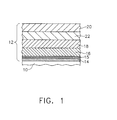
- EBC 12 may comprise a coating system including various combinations of the following: a bond coat layer 14, an optional silica layer 15, at least one transition layer 16, an optional compliant layer 18, an optional intermediate layer 22, and an optional outer layer 20, as shown generally in FIG. 1 and as set forth herein below.
- Bond coat layer 14 may comprise silicon metal, silicide, or a combination thereof, and may generally have a thickness of from about 0.1 mils to about 6 mils. Due to the application method as described herein below, there may be some local regions where the silicon bond coat is missing, which can be acceptable. For example, in one embodiment, bond coat layer can cover about 100% of the surface of the component, and in another embodiment, about 90% or more of the surface area of the component.
- silicide may include rare earth (Ln) silicides, chromium silicide (e.g. CrSi 3 ), niobium silicide (e.g. NbSi 2 , NbSi 3 ), molybdenum silicide (e.g. MoSi 2 , MoSi 3 ), tantalum silicide (e.g.TaSi 2 , TaSi 3 ), titanium silicide (e.g. TiSi 2 , TiSi 3 ), tungsten silicide (e.g. WSi 2 , W 5 Si 3 ), zirconium silicide (e.g. ZrSi 2 ), hafnium silicide (e.g. HfSi 2 ),
- Ln silicides chromium silicide (e.g. CrSi 3 ), niobium silicide (e.g. NbSi 2 , NbSi 3 ), molybdenum silicide (
- rare earth represented “(Ln)” refers to the rare earth elements of scandium (Sc), yttrium (Y), lanthanum (La), cerium (Ce), praseodymium (Pr), neodymium (Nd), promethium (Pm), samarium (Sm), europium (Eu), gadolinium (Gd), terbium (Tb), dysprosium (Dy), holmium (Ho), erbium (Er), thulium (Tm), ytterbium (Yb), lutetium (Lu), and mixtures thereof.
- Silica layer 15 can be amorphous or crystalline, and have an initial thickness of from about 0.0 mils to about 0.2 mils. However, the thickness of silica layer 15 can increase over time. Specifically, the silicon in bond coat layer 14 can oxidize slowly during the service life of the EBC to gradually increase the thickness of silica layer 15. This oxidation of bond coat 14 can protect the underlying ceramic component from oxidation since the bond coat is oxidized rather than the ceramic component. Silica layer 15 can, in some embodiments, also be doped with a doping composition, as defined herein below, due to diffusion of the sintering aid into the silica layer.
- a doping composition as defined herein below
- Transition layer 16 may comprise a rare earth disilicate, a doped rare earth disilicate, or a doped rare earth disilicate containing secondary materials, as defined below. More specifically, transition layer 16 may include from about 85% to about 100% by volume of the transition layer of a primary transition material and up to about 15% by volume of the transition layer of a secondary material, and in one embodiment from about 85% to about 99% by volume of the transition layer of the primary transition material and from about 1% to about 15% by volume of the transition layer of the secondary material. In another embodiment, transition layer 16 may comprise 100% primary transition material wherein the primary transition material can be doped, as described below.
- primary transition material refers to a rare earth disilicate (Ln 2 Si 2 O 7 ), or a doped rare earth disilicate.
- doped rare earth disilicate refers to Ln 2 Si 2 O 7 doped with a "doping composition” selected from the group consisting of iron (Fe), aluminum (Al), titanium (Ti), gallium (Ga), nickel (Ni), boron (B), an alkali, an alkali-earth, and Lnb rare earths, as defined herein below.
- secondary material refers to a material comprising a doping composition (as defined previously), and specifically, can be selected from the group consisting of Fe 2 O 3 , iron silicates, rare earth iron oxides, Al 2 O 3 , mullite, rare earth aluminates, rare earth aluminosilicates, TiO 2 , rare earth titanates, Ga 2 O 3 , rare earth gallates, NiO, nickel silicates, rare earth nickel oxides, Lnb metals, Lnb 2 O 3 , Lnb 2 Si 2 O 7 , Lnb 2 SiO 5 , borosilicate glass, alkaline earth silicates, alkaline earth rare earth oxides, alkaline earth rare earth silicates, and mixtures thereof.
- Any doping composition present in the primary material should correspond to the doping composition contained in any secondary material present (e.g. Fe-doped Ln 2 Si 2 O 7 with Fe 2 O 3 secondary material; Ti-doped Ln 2 Si 2 O 7 with TiO 2 secondary material; or Ni-doped Ln 2 Si 2 O 7 with rare earth nickel oxide secondary material, for example).
- any secondary material e.g. Fe-doped Ln 2 Si 2 O 7 with Fe 2 O 3 secondary material; Ti-doped Ln 2 Si 2 O 7 with TiO 2 secondary material; or Ni-doped Ln 2 Si 2 O 7 with rare earth nickel oxide secondary material, for example).
- Each transition layer 16 may have a thickness of from about 0.1 mils to about 40 mils, and may be made and applied to the underlying layer as set forth below. In one embodiment, there may be more than one transition layer present. In such instances, each transition layer may comprise the same or different combination of primary transition materials and secondary materials. Transition layer 16 may have a porosity level of from 0% to about 15% by volume of the transition layer, and in another embodiment, from about 0.01% to about 15% by volume of the transition layer.
- outer layer 20 may comprise a rare earth monosilicate, a doped rare earth monosilicate, or a doped rare earth monosilicate containing secondary material. More specifically, outer layer 20 can include from about 85% to about 100% by volume of the outer layer of a primary outer material and up to about 15% by volume of the outer layer of the previously defined secondary material, and in one embodiment from about 85% to about 99% by volume of the outer layer of a primary outer material and from about 1% to about 15% by volume of the outer layer of the secondary material. In another embodiment, outer layer 20 may comprise 100% primary outer material wherein the primary outer material can be doped as described below.
- outer layer 20 may have a thickness of from about 0.1 mils to about 3 mils, and may be made and applied to the underlying layer as set forth below. In one embodiment, outer layer 20 may have a porosity level of from 0% to about 30% by volume of the outer layer, and in another embodiment, from about 0.01% to about 30% by volume of the outer layer, and in another embodiment, from about 0.01% to about 15% by volume of the outer layer. In some embodiments, outer layer 20 can comprise cracks therein at a density of up to about 10 cracks/mm that can form during operation due to thermal expansion anisotropy.
- Lnb rare earth metal refers to a sub-set of rare-earth metals having a melting point below at least about 1450°C including lanthanum, cerium, praseodymium, neodymium, promethium, samarium, europium, gadolinium, terbium, dysprosium, and ytterbium.
- the sub-set can include only those rare earth elements having a melting point below about 1350°C including lanthanum, cerium, praseodymium, neodymium, promethium, samarium, europium, gadolinium, and ytterbium.
- the Lnb rare earth metal can be utilized with SiC-SiC CMCs having an operation limit of about 1357°C.
- alkaline earth can refer to magnesium (Mg), calcium (Ca), strontium (Sr), and barium (Ba).
- alkali refers to lithium (Li), potassium (K), and sodium (Na).
- Iron silicates can include compounds such as Fe 2 SiO 4 , and glasses of rare earth iron silicates.
- Rare earth iron oxides can include compounds such as garnets (Ln 3 Fe 5 O 12 ), monoclinic ferrites (Ln 4 Fe 2 O 9 ), and perovskites (LnFeO 3 ).
- “Rare-earth aluminates” can include compounds such as garnets (Ln 3 Al 5 O 12 ), monoclinic aluminates (Ln 4 Al 2 O 9 ), and perovskites (LnAlO 3 ).
- "Rare earth aluminates” can include glassy materials comprised of about 35-50 wt% Ln 2 O 3 , about 15-25 wt% Al 2 O 3 , and about 25-50 wt% SiO 2 .
- “Rare-earth titanates” can include compounds such as Ln 2 Ti 2 O 7 (pyrochlore) and Ln 2 TiO 5 .
- Race-earth gallates can include compounds such as garnets (Ln 3 Ga 5 O 12 ), monoclinic gallates (Ln 4 Ga 2 O 9 ), perovskites (LnGaO 3 ), and Ln 3 GaO 6 .
- Nickel silicates can include compounds such as Ni 2 SiO 4 .
- Borosilicate glass can refer to any amorphous material containing up to about 15% by weight boron oxide (B 2 O 3 ), up to about 10% alkali oxide selected from the group consisting of sodium (Na 2 O), potassium (K 2 O), lithium (Li 2 O), or any combinations of thereof, up to about 10% alumina (Al 2 O 3 ), and a balance of silica (SiO 2 ).
- Alkaline earth silicates can include compounds such as Mg 2 SiO 4 , MgSiO 3 , Ca 2 SiO 4 , Ca 3 SiO 5 , Ca 3 Si 2 O 7 , CaSiO 3 , Ba 2 SiO 4 , BaSiO 3 , Ba 2 Si 3 O 8 , BaSi 2 O 5 , Sr 2 SiO 4 , and SrSiO 3 .
- Alkali earth rare earth oxides can include compounds such as BaLn 2 O 4 , Mg 3 Ln 2 O 6 , SrLn 2 O 4 , and Sr 2 Ln 2 O 5 .
- Alkaline earth rare earth silicates can include oxyapatite materials (i.e. Ae 2 Ln 8 Si 6 O 26 ).
- compliant layer 18 may include from about 85% to about 100% by volume of the compliant layer of a primary compliant material and up to about 15% by volume of the compliant layer of a secondary compliant material, and in one embodiment from about 85% to about 99% by volume of the compliant layer of a primary compliant material and from about 1% to about 15% by volume of the compliant layer of the secondary compliant material. In another embodiment, compliant layer 18 may comprise 100% by volume of the compliant layer of a primary compliant material wherein the primary outer material may be doped with a rare earth element.
- primary compliant material refers to BSAS, or a rare earth doped BSAS
- secondary compliant material refers to Ln 2 O 3 , Ln 2 Si 2 O 7 , Ln 2 SiO 5 , Ln 3 Al 5 O 12 , Al 2 O 3 , mullite, and combinations thereof.
- Compliant layer 20 may have a thickness of from about 0.1 mils to about 40 mils, and may be made and applied as set forth below.
- compliant layer 18 may have a porosity level of from 0% to about 30% by volume of the compliant layer, and in another embodiment, from about 0.01% to about 30% by volume of the compliant layer, and in another embodiment, from about 0.01% to about 15% by volume of the compliant layer.
- Intermediate layer 22 can comprise the previously defined primary outer materials of rare earth monosilicate or doped rare earth monosilicate. Similar to the silica layer, intermediate layer 22 can form during the service life of the EBC. More specifically, high temperature steam penetrates the outer layer 20, and as the steam reacts with the primary transition material of the transition layer to volatilize SiO 2 , intermediate layer 22 can form.
- the EBC systems described herein may include in one embodiment, component 10, bond coat layer 14, and transition layer 16; in another embodiment, component 10, bond coat layer 14, transition layer 16, and outer layer 20; in another embodiment, component 10, bond coat layer 14, transition layer 16, compliant layer 18, and outer layer 20; in another embodiment, component 10, bond coat layer 14, transition layer 16, compliant layer 18, transition layer 16, and outer layer 20; in another embodiment, component 10, bond coat layer 14, silica layer 15, and transition layer 16; in another embodiment, component 10, bond coat layer 14, silica layer 15, transition layer 16, and outer layer 20; in another embodiment, component 10, bond coat layer 14, silica layer 15, transition layer 16, compliant layer 18, and outer layer 20; in another embodiment, component 10, bond coat layer 14, silica layer 15, transition layer 16, compliant layer 18, transition layer 16, and outer layer 20; in another embodiment, component 10, bond coat layer 14, silica layer 15, transition layer 16, compliant layer 18, transition layer 16, and outer layer 20; in another embodiment, component 10, bond coat layer 14, transition layer 16, intermediate layer 22, and outer layer 20; in another embodiment, component 10, bond coat layer 14, silica layer
- the EBC system may comprise component 10, bond coat layer 14, transition layer 16, and compliant layer 18; in another embodiment, component 10, bond coat layer 14, silica layer 15, transition layer 16, and compliant layer 18.
- Such embodiments can be suitable for use in environments having a temperature of up to about 1538°C (2800°F).
- the EBC can be made and applied in accordance with the description below.
- Bond coat layer 14 may be applied by plasma spray processes, chemical vapor deposition processes, electron beam physical vapor deposition processes, dipping in molten silicon, sputtering processes, and other conventional application processes known to those skilled in the art.
- silica layer 15 can form during the service life of the EBC. Specifically, oxygen in the surrounding atmosphere can diffuse through any of the outer layer, compliant, and transition layer(s) present in the EBC and react with the silicon of bond coat layer 14 to form silica layer 15. Alternately, silica layer 15 may be intentionally deposited by chemical vapor deposition, plasma spray, slurry deposition, or other conventional method.
- intermediate layer 22 can also form during the service life of the EBC when high temperature steam reacts with transition layer 16, as previously described.
- the manufacturing and application processes for transition layer 16, compliant layer 18 and outer layer 20 can consist of a solvent based slurry deposition cycle including sintering aids to lower the temperature needed to densify the layers.
- the slurry deposition cycle can generally include slurry formation, slurry application, drying, and sintering, with optional masking, leveling, sintering aid infiltration, mask removal, and binder burnout steps, as set forth below.
- slurries of varying compositions can be used to make EBC layers of varying composition and that multiple slurry deposition cycles can be used to build up the total thickness of a particular layer.
- Each layer can have the thickness set forth previously with the average thickness per slurry deposition cycle depending primarily on the slurry solids loading, sintering aid concentration, and number of dip, spray, or paint passes.
- the slurries described in the embodiments herein can comprise various slurry components, but generally include an organic solvent, ceramic particles, sintering aid, and organic processing aids.
- the slurry may comprise from about 6.8 wt% to about 96.1 wt% solvent, from about 0 wt% to about 8.9 wt% of a dispersant, from about 0 wt% to about 15.4 wt % of a plasticizer, from about 3.9 wt% to about 93.2 wt % primary material, from about 0 wt% to about 15.4 wt% thickener, from about 0 wt% to about 1 wt% surfactant, and from about 0 wt% to about 20 wt % slurry sintering aid if there is one sintering aid, or alternately, from about 0 wt % to about 79.9 wt % slurry sintering aid if there are two sintering aids present
- organic solvent refers to methanol, ethanol, propanol, butanol, pentanol, hexanol, heptanol, octanol, nonanol, decanol, dodecanol, acetone, methyl isobutyl ketone (MIBK), methyl ethyl ketone (MEK), toluene, ethylbenzene, propyl benzene, methoxybenzene, heptane, octane, nonane, decane, xylene, mineral spirits, naptha (such as VM&P naptha), tetrahydrofuran, ethers, and combinations thereof.
- MIBK methyl isobutyl ketone
- MEK methyl ethyl ketone
- toluene ethylbenzene
- propyl benzene propyl benzene
- Primary materials may refer to Ln 2 Si 2 O 7 , Ln 2 SiO 5 , or BSAS depending on which layer is being made.
- Disposant can refer to polyacrylic acid, polyacrylic acid-polyethylene oxide copolymers, polymethacrylic acid, polyethylenimine, phosphate esters, menhaden fish oil, polyethylene oxide, polysilazane, and combinations thereof.
- Polymer can refer to ethylene glycol, diethylene glycol, triethylene glycol, tetraethylene glycol glycerol, glycerin, polyethylene glycol, dibutyl phthalate, Bis(2-ethylhexyl) phthalate, Bis(n-butyl)phthalate, Butyl benzyl phthalate, Diisodecyl phthalate, Di-n-octyl phthalate, Diisooctyl phthalate, Diethyl phthalate, Diisobutyl phthalate, Di-n-hexyl phthalate, Di(propylene glycol) dibenzoate, Di(ethylene glycol) dibenzoate, tri(ethylene glycol) dibenzoate, and combinations thereof.
- slurry sintering aid can refer to sintering aid compositions suitable for inclusion in the slurry.
- a slurry sintering aid selected from iron oxide, gallium oxide, aluminum oxide, nickel oxide, titanium oxide, boron oxide, and alkaline earth oxides; carbonyl iron; iron metal, aluminum metal, boron, nickel metal, hydroxides including iron hydroxide, gallium hydroxide, aluminum hydroxide, nickel hydroxide, titanium hydroxide, alkaline earth hydroxides; carbonates including iron carbonate, gallium carbonate, aluminum carbonate, nickel carbonate, boron carbonate, and alkaline earth carbonates; oxalates including iron oxalate, gallium oxalate, aluminum oxalate, nickel oxalate, titanium oxalate; and
- the "slurry sintering aid" may include rare earth nitrate, rare earth acetate, rare earth chloride, rare earth oxide, ammonium phosphate, phosphoric acid, polyvinyl phosphoric acid, and combinations thereof.
- the slurry can comprise from about 0 wt% to about 59.3 wt%, and in one embodiment from about 0.01 wt% to about 59.3 wt%, of an Lnb metal slurry sintering aid as defined previously herein, and from about 0 wt% to about 20.6 wt%, and in one embodiment from about 0.01 wt% to about 20.6 wt%, of a SiO 2 slurry sintering aid.
- the Lnb and SiO 2 content can be held such that the mole ratio of Lnb to SiO 2 is about 1 to 1 for slurries containing rare earth disilicate primary transition material, and about 2 to 1 for slurries containing rare earth monosilicate primary outer material.
- solvent-soluble iron salts can include ethoxide, iron 2,4-pentanedionate, and iron tetramethylheptanedionate
- solvent-soluble gallium salts can include gallium 8-hydroxyquinolinate, gallium 2,4-pentanedionate, gallium ethoxide, gallium isopropoxide, and gallium 2,2,6,6-tetramethylheptanedionate
- solvent-soluble aluminum salts can include butoxide, aluminum di-s-butoxide ethylacetoacetate, aluminum diisopropoxide ethylacetoacetate, aluminum ethoxide, aluminum ethoxyethoxyethoxide, aluminum 3,5-heptanedionate, aluminum isopropoxide, aluminum 9-octadecenylacetoacetate diisopropoxide, aluminum 2,4-pentanedionate, aluminum pentanedionate bis(ethylacetoa)
- Thickener refers to polyvinyl butyral, polyvinyl acetate, poly(isobutyl methacrylate), poly[(n-butyl methacrylate-co-isobutyl methacrylate)], methyl methacrylate copolymers, ethyl methacrylate copolymers, poly methyl methacrylate, polyethyl methacrylate, polyvinylpyroline, ethyl cellulose, nitrocellulose, and other solvent soluble cellulose derivatives, and combinations thereof.
- “Surfactant” refers to compositions selected from the group consisting of fluorocarbons, dimethylsilicones, and ethoxylated acetylenic diol chemistries (e.g. commercial surfactants in the Surfynol® series such as Surfynol® 420 and 502 (Air Products and Chemicals, Inc.)), and combinations thereof.
- organic processing aids refers to any dispersants, plasticizers, thickeners, and surfactants present in the slurry. These organic processing aids are comprised primarily of carbon and other elements that volatilize during processing such that they are not present in the post-sintered coating.
- the slurry can be formed by combining any or all of the previously described slurry components with mixing media in a container.
- the mixture can be mixed using conventional techniques known to those skilled in the art such as shaking with up to about a 1 inch (about 25.4 mm) diameter alumina or zirconia mixing media, ball milling using about a 0.25 inch to about a 1 inch (about 0.64cm to about 2.54cm) diameter alumina or zirconia mixing media, attritor milling using about a 1mm to about a 5mm diameter zirconia-based mixing media, planetary ball milling using from about a 1mm to about a 5mm diameter zirconia-based media, or mechanical mixing or stirring with simultaneous application of ultrasonic energy.
- the mixing media or ultrasonic energy can break apart any agglomerated ceramic particles in the slurry. Any mixing media present may then be removed by straining, for example.
- thickener may be added to the slurry if desired and the resulting mixture may be agitated by such methods as mechanical stirring, rolling, blending, shaking, and other like methods until the thickener is fully dissolved, generally after about 5 to about 60 minutes.
- the addition of the sintering aids may follow along with mixing using the previously described methods until the sintering aids dissolve, which is about 5 to about 60 minutes.
- the slurry can be filtered through screens of varying mesh sizes to remove any impurities that may be present, such as after the initial mixing of the slurry or after use of the slurry to deposit coating layers.
- a 325 mesh screen for example, can be used to filter out impurities having an average size of about 44 microns or greater.
- the slurry can be agitated indefinitely by slow rolling, slow mechanical mixing, or other like methods to avoid trapping air bubbles in the slurry.
- the slurry may be refreshed by adding additional solvent to account for that which has evaporated during processing.
- the slurry can be set aside until needed for application.
- masking can be applied to the ceramic component before the slurry is applied to prevent coating specific areas of the component.
- Masking may be carried out using conventional techniques known to those skilled in the art including, but not limited to, tapes, tooling, and paint-on adhesives.
- the slurry can be applied to the component to produce a coated component.
- the slurry can be applied to the component (or on top of a previously applied layer) using any conventional slurry deposition method known to those skilled in the art, including but not limited to, dipping the component into a slurry bath, or painting, rolling, stamping, spraying, or pouring the slurry onto the component. Slurry application can be carried out manually or it may be automated.
- the slurry may be leveled to remove excess slurry material.
- Leveling may be carried out using conventional techniques such as, but not limited to, spinning, rotating, slinging the component, dripping with or without applied vibration, or using a doctor blade, to remove excess slurry material. Similar to the slurry application, leveling can be conducted manually or it may be automated.
- the coated component can be dried. Drying may be carried out in an enclosed area having additional organic solvent present in secondary containers. This can help slow the drying process because the atmosphere can be saturated with organic solvent. Since this process utilizes an organic solvent, it is not strongly sensitive to humidity. Temperature variation can be used to control the drying rate, however, those skilled in the art will understand that temperatures can be kept below the flash point of the organic solvent. Placing a coated component in a vacuum chamber and pulling a vacuum can also be used to accelerate drying.
- any masking present may then be removed by peeling off tapes and adhesives, pyrolysis of tapes and adhesives, or removing multi-use tooling. Any rough edges remaining after masking removal may be scraped or cut away using a sharp or abrasive tool.
- burnout of the organic processing aids may be carried out by placing the dried component in an elevated temperature environment so that any residual solvent can be evaporated and the organic processing aids can be pyrolyzed.
- burnout of the organic processing aids may be accomplished by heating the dried component at a rate of from about 1°C/min to about 15°C/min to a temperature of from about 400°C to about 1000°C and holding the component at this temperature for from about 0 to about 10 hours.
- the coated component may be heated at a rate of from about 2°C/min to about 6°C/min to a temperature of from about 600°C to about 800°C and holding the component at this temperature for from about 0 to about 10 hours.
- the hold time can be eliminated by slowly ramping up to the target temperature without holding, followed by ramping up or down to another temperature at a different rate.
- binder burnout can occur rapidly by placing the coated component into a furnace heated to a temperature of from about 400°C to about 1400°C.
- Binder burnout and sintering heat treatments may be carried out in an ambient air atmosphere, or in an inert gas atmosphere where the inert gas is selected from hydrogen, a noble gas such as helium, neon, argon, krypton, xenon, or mixtures thereof.
- the inert gas atmosphere can be used in conjunction with Lnb and SiO 2 sintering aids so as not to convert the rare earth metal to an oxide before it melts. Maintaining the Lnb metal in a metal state can promote liquid phase sintering and subsequent reaction with the SiO 2.
- the dried component may then be sintered to produce a component comprising an environmental barrier coating.
- Sintering can serve to simultaneously densify and impart strength to the coating. Additionally, in the case of the transition and compliant layers of the EBC, sintering can impart a hermetic seal against high temperature steam present in the engine environment. In the case of the outer layer, sintering can provide a dense barrier against the infiltration of molten silicates, such as calcium-magnesium aluminosilicate (CMAS) that may be encountered as a result of particulate contamination (i.e. dirt and sand) in the engine environment. Sintering can be carried out using a conventional furnace, or by using such methods as microwave sintering, laser sintering, infrared sintering, and the like.
- CMAS calcium-magnesium aluminosilicate
- Sintering can be accomplished by heating the dried component at a rate of from about 1°C/min to about 15°C/min to a temperature of from about 1100°C to about 1700°C and holding the component at that temperature for from about 0 to about 24 hours.
- sintering can be accomplished by heating the coated component at a rate of from about 5°C/min to about 15°C/min to a temperature of from about 1300°C to about 1375°C and holding the component at that temperature for from about 0 to about 24 hours.
- sintering can occur rapidly by placing the coated component into a furnace heated to a temperature of from about 1000°C to about 1400°C.
- all layers of the EBC can be applied, one on top of the other, before masking removal, organic processing aid burnout, and sintering are carried out.
- the layer should be dried, or partially dried, before the application of the subsequent layer.
- the sintering aid does not need to be added directly to the transition or outer layer of the slurry to achieve the desired result.
- the sintering aid can be added to one layer of the EBC slurry, and during sintering, the sintering aid can diffuse throughout the EBC to the remaining layers.
- a primary material slurry with no sintering aid can be densified by applying the layer, allowing it to dry, and then back infiltrating a sol-gel solution comprising a sintering aid prior to heat treatment as explained below.
- Infiltration may allow for the densification of a thicker layer of EBC material at one time. Moreover, infiltration is a way to add more sintering aid after sintering if the coating is not as dense as desired.
- the sol-gel solution used for infiltration may be a solution of an organic solvent and a solvent soluble salt sintering aid, as defined previously, or a solution of water and a water soluble salt sintering aid.
- water soluble salt sintering aid can refer to "water-soluble iron salts” such as iron nitrate and iron acetate; “water-soluble gallium salts” such as gallium nitrate and gallium acetate; “water-soluble aluminum salts” such as aluminum nitrate and aluminum acetate; “water-soluble nickel salts” such as nickel nitrate and nickel acetate; “water-soluble titanium salts” such as titanium chloride; “water-soluble boron salts” such as boric acid and ammonium borate; and “water-soluble alkaline earth salts” such as include Mg(NO 3 ) 2 , Ca(NO 3 ) 2 , Sr(NO 3 ) 2 , Ba(NO 3 ) 2 , MgC 2 H 3 O 2 , CaC 2 H 3 O 2 , SrC 2 H 3 O 2 , and BaC 2 H 3 O 2 .
- sintering aid(s) can refer to any of a “slurry sintering aid,” a “solvent soluble sintering aid,” or a “water soluble salt sintering aid,” as defined previously.
- sintering aids can increase the rate of diffusion of primary material such that surface area reduction (i.e. high surface area particles consolidating to form a dense coating) can occur at lower temperatures than it would have absent the sintering aid.
- surface area reduction i.e. high surface area particles consolidating to form a dense coating
- sintering at lower temperatures i.e. about 1357°C or below
- greater than about 85% for the transition layer, greater than about 70% for the compliant layer, and greater than about 70% for the outer layer) coating that can be less susceptible to the penetration of hot steam from the engine environment, but can also help prevent the degradation of the mechanical properties of the underlying component that could result from prolonged exposure to higher temperatures.
- Sintering aids can act in a variety of ways depending on the amount of sintering aid included in the EBC and the time at which the coating is exposed to sintering temperatures.
- the sintering aid can dissolve completely into the primary material (i.e. primary transition, outer, or compliant, material) to "dope" the material.
- the remaining insoluble portion of sintering aid can react with the primary material to form the secondary material (i.e. secondary transition, outer, or compliant material).
- primary material and secondary material can be present as described previously, along with residual sintering aid.
- the secondary material when the secondary material is highly volatile in high temperature steam, such as but not limited to, alkali silicates, alkaline earth silicates, mullite, iron silicate, borosilicate glass, nickel silicate, and residual sintering aids of iron, aluminum, titanium, gallium, nickel, boron, alkali, and alkali-earth compounds, as long as the total volume of secondary material, plus porosity (plus residual sintering aid when present) in either of the intermediate layer or compliant layer (when present) of the EBC remains about 15% by volume or less, the hermetic seal can be maintained.
- the secondary material when the secondary material is highly resistant to volatilization in high temperature steam, such as when the secondary material comprises a rare earth containing compound, such as but not limited to rare earth oxide, rare earth titanate, rare earth iron compound, rare earth gallate, rare earth aluminate, and rare earth aluminosilicate, the porosity in either of the intermediate or compliant layer (when present) of the EBC need remain about 15% by volume or less to maintain the hermetic seal.
- a rare earth containing compound such as but not limited to rare earth oxide, rare earth titanate, rare earth iron compound, rare earth gallate, rare earth aluminate, and rare earth aluminosilicate
- the densified coating layer might not initially include any detectable secondary materials.
- the secondary materials may never become detectable.
- the secondary materials can become detectable using techniques such as x-ray diffraction, electron microscopy, electron dispersive spectroscopy (EDS), and the like.
- EBC embodiments described herein can offer a variety of benefits over current EBCs and manufacturing processes thereof.
- the inclusion of a sintering aid in the EBC embodiments herein can permit sintering at lower temperatures (i.e. about 1357°C or below). This can result in a highly dense (i.e. greater than about 85% for the transition layer, and greater than about 70% for each of the outer, and compliant, layers) coating that can be less susceptible to the penetration of hot steam from the engine environment, and can also help prevent the degradation of the mechanical properties of the underlying component that could result from prolonged exposure to higher temperatures.
- the embodiments set forth herein can be made at less expense than current EBCs due to the use of the slurry deposition process, which is made possible by the incorporation of sintering aids into the various layers.
- the present embodiments can provide for EBCs having a more uniform thickness than conventional techniques, such as plasma spraying, even when applying thin layers ( ⁇ 2 mils).
- the slurry deposition process can allow for the application of the EBCs to internal component passages as well as the ability to produce smooth surface finishes without an additional polishing step.
- EBC develops small and/or narrow defects (e.g. about 10 microns to about 5mm in diameter; or about 10 microns to about 1mm in width) that need to be repaired.
- the following repair processes are applicable to the EBCs described herein and may be carried out after sintering of an individual EBC layer, or after sintering the entire applied EBC, as explained herein below.
- repairs may include remedying defects in one or more individual layers as the EBC is being applied using the methods described herein.
- the repair can be carried out after sintering a given layer by applying a repair slurry comprising the same slurry materials used to make the layer having the defects.
- a repair slurry comprising the same slurry materials used to make the layer having the defects.
- the repair slurry can comprise a higher solids loading of primary material ceramic particles than the original slurry layer as this can reduce shrinkage on drying and sintering of the repaired portion of the coating.
- the solids loading of primary material ceramic particles in the repair slurry can be greater than about 30% to about 55% by volume (as opposed to greater than about 10% by volume in one embodiment of the original slurry, and from about 10% to about 55% by volume in another embodiment of the original slurry used to make the layer).
- the repair slurry may be applied using any conventional method including those described previously, and the resulting "repair(ed) coating" may then be processed as described previously herein before application of any subsequent layer of the EBC.
- repairs may include fixing defects after application and sintering of the entire EBC.
- the repair may be carried out on the EBC having defects using a transition layer repair slurry comprising the same materials present in the previously defined transition layer slurry (i.e. primary transition material, a sintering aid, and optionally secondary material).
- This particular repair slurry can seep into any defects present in the EBC and provide a hermetic seal to the repaired EBC coating after sintering.
- the solids loading of the transition layer repair slurry may comprise upwards of about 30% to 55% by volume.
- repair processes may be used to reduce surface roughness of a plasma sprayed EBC having any composition. Specifically, if the surface roughness of a plasma sprayed EBC is unacceptable the coating can be smoothed over by applying either of the previously described transition layer slurry or outer layer slurry. When applied over the plasma sprayed EBC, the transition layer slurry or outer layer slurry can fill in any gaps, grooves, or uneven portions of the plasma sprayed coating and reduce the surface roughness to an acceptable degree.
- transition layer slurry or outer layer slurry can comprise a thickness of at least about 0.5 mils, and in another embodiment from about 0.5 mils to about 3 mils.
- the applied transition layer slurry can then be processed as described previously to produce a repaired EBC having an acceptable surface roughness. Additional slurry layers may be applied to the EBC if desired.
- Such repair processes can provide the ability to repair localized defects, at varying points during the application or life of the coating, as opposed to stripping off and reapplying the entire coating. This, in turn, can result in a savings of time, labor, and materials.
- Example 1 A silicon bond coat was applied to a SiC-SiC CMC using a conventional air plasma spray process.
- a primary transition material slurry was made by first mixing ytterbium disilicate (primary transition material), iron oxide nanoparticles (sintering aid), ethanol (solvent), and polyethylenimine (dispersant) in a plastic container, along with enough 0.25 inch (6.35mm) diameter, spherical zirconia media to line the bottom of container. This mixture was placed on a roller mill for 15 hours. After taking the container off of the roller mill, the zirconia media was removed and the slurry was filtered through a 325 mesh screen to remove any large particle agglomerates.
- the resulting primary transition material slurry (Slurry A) consisted of 56.11% ytterbium disilicate, 0.54% iron oxide, 0.57% polyethylenimine, and the balance ethanol (all percents by weight).
- the silicon-coated ceramic component was dipped into Slurry A, dried in ambient conditions, re-dipped into Slurry A, dried in ambient conditions, and heat-treated at 10°C/minute to 1000°C to burn out any residual organic materials. Then, the temperature was increased at 10°C/minute from 1000°C to 1344°C and held for 10 hours to form a transition layer comprising iron-doped ytterbium disilicate.
- the entire heat treatment was carried out in air. The heating environment resulted in the transition layer having a porosity of less than 15% by volume.
- a primary outer material slurry was made by first mixing ytterbium monosilicate (primary outer material), iron oxide nanoparticles (sintering aid), ethanol (solvent), and polyethylenimine (dispersant) in a plastic container, along with enough 0.25 inch (6.35mm) diameter, spherical zirconia media to line the bottom of container. This mixture was placed on a roller mill for 15 hours. After taking the container off of the roller mill, the zirconia media was removed and the slurry was filtered through a 325 mesh screen to remove any large particle agglomerates.
- the resulting primary outer material slurry consisted of 61.19% ytterbium monosilicate, 0.29% iron oxide, 0.61% polyethylenimine, and the balance ethanol (all percents by weight).
- the silicon and transition layer-coated ceramic component was dipped into Slurry B, dried in ambient conditions, re-dipped into Slurry B, dried in ambient conditions, and heat-treated at 10°C/minute to 1000°C to burn out any residual organic materials. Then, the temperature was increased at 10°C/minute from 1000°C to 1344°C and held for 10 hours to densify the transition layer. After heat treatment, the layer comprised iron-doped yttrium monosilicate. The entire heat treatment was carried out in air. The heating environment resulted in the transition layer having a porosity of less than 15% by volume. The dipping, drying, and heat treatments were repeated 2 times to build thickness of the outer layer.
- FIG. 2 shows a SEM micrograph of this coating microstructure with the air plasma spray silicon bond coat (100), a thin silica layer (3.9 micrometers) (102), transition layer (104), and outer layer (106).
- the outer layer and transition layer appeared to consist only of iron-doped primary materials (iron-doped ytterbium monosilicate and iron-doped ytterbium disilicate, respectively), x-ray diffraction was not able to detect any secondary material present in the EBC.
- EDS analysis of the layers suggested that the iron oxide had dissolved into the primary materials.
- Example 2 A CMC (101) coated with the EBC of Example 1 was exposed to 2400°F (1316°C) steam for 1000 hours.
- FIG. 3 shows a SEM micrograph of this coating after high temperature steam exposure with silicon bond coat (100), a silica layer (102) that has grown to approximately 7.0 micrometer thickness, an iron-doped ytterbium disilicate transition layer (104), and a dense ytterbium monosilicate outer layer (106) with cracks.
- Some ytterbium disilicate has formed around the cracks in the monosilicate layer as an artifact of high gaseous silicon content in the static atmosphere of the steam test.
- Example 3 To demonstrate proof of principle, a primary transition layer was deposited on a silicon metal wafer using a slurry deposition process.
- a primary transition material slurry was made by first mixing ytterbium disilicate powder (primary transition material), gallium oxide powder (sintering aid), ethanol (solvent), and polyethylenimine (dispersant) in a plastic container, along with enough 0.25 inch (6.35mm) diameter, spherical zirconia media to line the bottom of container. This mixture was placed on a roller mill for 15 hours. After taking the container off of the roller mill, the zirconia media was removed and the slurry was filtered through a 325 mesh screen to remove any large particle agglomerates.
- the resulting primary transition material slurry (Slurry C) consisted of 56.35% ytterbium disilicate, 0.64% gallium oxide, 0.57% polyethylenimine, and the balance ethanol (all percents by weight).
- the silicon-coated ceramic component was dipped into Slurry C, dried in ambient conditions, re-dipped into Slurry C, dried in ambient conditions, and heat-treated at 10°C/minute to 1000°C to burn out any residual organic materials. Then, the temperature was increased at 10°C/minute from 1000°C to 1344°C and held for 10 hours to form a transition layer comprising iron-doped ytterbium disilicate. The entire heat treatment was carried out in air.
- the heating environment resulted in the transition layer (108) having a porosity of less than 15% by volume as shown in FIG. 4 .
- No secondary phases were observed in this coating via electron microscope examination. EDS analysis suggested that the gallium had dissolved into the ytterbium disilicate primary material.
Landscapes
- Chemical & Material Sciences (AREA)
- Engineering & Computer Science (AREA)
- Ceramic Engineering (AREA)
- Materials Engineering (AREA)
- Structural Engineering (AREA)
- Organic Chemistry (AREA)
- Mechanical Engineering (AREA)
- General Engineering & Computer Science (AREA)
- Turbine Rotor Nozzle Sealing (AREA)
- Inorganic Chemistry (AREA)
- Dispersion Chemistry (AREA)
- Physics & Mathematics (AREA)
- Plasma & Fusion (AREA)
- Manufacturing & Machinery (AREA)
- Application Of Or Painting With Fluid Materials (AREA)
- Nanotechnology (AREA)
Applications Claiming Priority (2)
| Application Number | Priority Date | Filing Date | Title |
|---|---|---|---|
| US23028909P | 2009-07-31 | 2009-07-31 | |
| US12/642,010 US9005716B2 (en) | 2009-07-31 | 2009-12-18 | Method for making solvent based environmental barrier coatings using sintering aids |
Publications (2)
| Publication Number | Publication Date |
|---|---|
| EP2284140A2 true EP2284140A2 (fr) | 2011-02-16 |
| EP2284140A3 EP2284140A3 (fr) | 2015-11-04 |
Family
ID=42753523
Family Applications (1)
| Application Number | Title | Priority Date | Filing Date |
|---|---|---|---|
| EP10171503.5A Withdrawn EP2284140A3 (fr) | 2009-07-31 | 2010-07-30 | Procédé de fabrication de revêtements de barrière environnementale à base de solvants utilisant des supports de frittage |
Country Status (4)
| Country | Link |
|---|---|
| US (1) | US9005716B2 (fr) |
| EP (1) | EP2284140A3 (fr) |
| JP (1) | JP5890957B2 (fr) |
| CA (1) | CA2711347C (fr) |
Cited By (3)
| Publication number | Priority date | Publication date | Assignee | Title |
|---|---|---|---|---|
| WO2013013677A1 (fr) * | 2011-07-22 | 2013-01-31 | Danmarks Tekniske Universitet | Procédé pour la densification de couches de céramique, plus précisément de couches de céramique pour la technologie des éléments à oxyde solide (soc), et produits obtenus par le procédé |
| US9926805B2 (en) | 2009-07-31 | 2018-03-27 | General Electric Company | Solvent based slurry compositions for making environmental barrier coatings and environmental barrier coatings comprising the same |
| US11072566B2 (en) | 2014-06-30 | 2021-07-27 | General Electric Company | Thermal and environmental barrier coating compositions and methods of deposition |
Families Citing this family (19)
| Publication number | Priority date | Publication date | Assignee | Title |
|---|---|---|---|---|
| US20090186237A1 (en) | 2008-01-18 | 2009-07-23 | Rolls-Royce Corp. | CMAS-Resistant Thermal Barrier Coatings |
| US9624583B2 (en) | 2009-04-01 | 2017-04-18 | Rolls-Royce Corporation | Slurry-based coating techniques for smoothing surface imperfections |
| EP2596068B1 (fr) | 2010-07-23 | 2015-09-02 | Rolls-Royce Corporation | Revêtements formant barrière thermique comprenant des couches de revêtement formant barrière thermique résistant au scma |
| WO2012027442A1 (fr) | 2010-08-27 | 2012-03-01 | Rolls-Royce Corporation | Revêtements barrières environnementales à base de silicate de terres rares |
| JP5862234B2 (ja) * | 2011-11-28 | 2016-02-16 | 株式会社Ihi | 平滑表面を有するセラミックス基複合部材およびその製造方法 |
| WO2014144437A1 (fr) | 2013-03-15 | 2014-09-18 | Rolls-Royce Corporation | Restauration de revêtement à base de suspension |
| JP6267908B2 (ja) * | 2013-09-27 | 2018-01-24 | 三井金属鉱業株式会社 | 分散液及びその製造方法並びに薄膜 |
| CN105814007B (zh) | 2013-12-12 | 2019-05-07 | 通用电气公司 | 以聚合物凝胶形式沉积可磨耗涂层的方法 |
| MX2017011083A (es) | 2015-03-02 | 2017-11-10 | Saint Gobain | Separador reforzado con fibra de vidrio para unidad de acristalamiento aislante. |
| EP3141631B1 (fr) | 2015-09-10 | 2018-03-14 | Rolls-Royce High Temperature Composites Inc | Application de couche de liaison contenant du silicium metal sur des substrats en ceramique ou en composite a matrice ceramique |
| US10822687B2 (en) | 2016-02-29 | 2020-11-03 | General Electric Company | Environmental barrier coating and methods of preparation |
| CN106977234B (zh) * | 2016-06-02 | 2018-10-19 | 北京航空航天大学 | 超高温多层梯度复合环境障涂层的制备方法 |
| US10801111B2 (en) | 2017-05-30 | 2020-10-13 | Honeywell International Inc. | Sintered-bonded high temperature coatings for ceramic turbomachine components |
| US20190017177A1 (en) | 2017-07-17 | 2019-01-17 | Rolls-Royce Corporation | Thermal barrier coatings for components in high-temperature mechanical systems |
| US11655543B2 (en) | 2017-08-08 | 2023-05-23 | Rolls-Royce Corporation | CMAS-resistant barrier coatings |
| US10851656B2 (en) | 2017-09-27 | 2020-12-01 | Rolls-Royce Corporation | Multilayer environmental barrier coating |
| US11325869B1 (en) * | 2017-10-20 | 2022-05-10 | United States Of America As Represented By The Administrator Of National Aeronautics And Space Administration | Environmental barrier coatings for improved temperature capabilities and longevity |
| US12145893B2 (en) | 2018-08-17 | 2024-11-19 | Rtx Corporation | Coating repair for ceramic matrix composite (CMC) substrates |
| US11851380B2 (en) | 2021-05-26 | 2023-12-26 | General Electric Company | Slurry processing for deposition of rare earth hafnium tantalate based barrier coatings |
Family Cites Families (36)
| Publication number | Priority date | Publication date | Assignee | Title |
|---|---|---|---|---|
| CA1136388A (fr) | 1978-01-09 | 1982-11-30 | Kennecott Corporation | Methode de production d'articles en ceramique frittes a l'aide d'un liquide a teneur de bore |
| JPS6067601A (ja) * | 1983-09-22 | 1985-04-18 | Toshiba Corp | 焼結体の製造方法 |
| JP3346799B2 (ja) | 1992-08-24 | 2002-11-18 | 株式会社日立製作所 | 手話通訳装置 |
| US5518673A (en) | 1993-10-14 | 1996-05-21 | Saint-Gobain/Norton Industrial Ceramics Corp. | Silicon nitride ceramic having high fatigue life and high toughness |
| JPH09110533A (ja) | 1995-10-12 | 1997-04-28 | Ngk Spark Plug Co Ltd | 窒化珪素質焼結体及びその製造方法 |
| US5759932A (en) | 1996-11-08 | 1998-06-02 | General Electric Company | Coating composition for metal-based substrates, and related processes |
| US6294261B1 (en) * | 1999-10-01 | 2001-09-25 | General Electric Company | Method for smoothing the surface of a protective coating |
| US6444335B1 (en) * | 2000-04-06 | 2002-09-03 | General Electric Company | Thermal/environmental barrier coating for silicon-containing materials |
| US6645649B2 (en) | 2000-10-31 | 2003-11-11 | Kyocera Corporation | Surface-coated sintered body of silicon nitride |
| JP2003002752A (ja) | 2001-06-25 | 2003-01-08 | Isuzu Motors Ltd | セラミックスの開発方法 |
| US6644917B2 (en) | 2001-08-14 | 2003-11-11 | General Electric Company | Smart coating system with chemical taggants for coating condition assessment |
| US6759151B1 (en) * | 2002-05-22 | 2004-07-06 | The United States Of America As Represented By The Administrator Of The National Aeronautics And Space Administration | Multilayer article characterized by low coefficient of thermal expansion outer layer |
| US6933061B2 (en) | 2002-12-12 | 2005-08-23 | General Electric Company | Thermal barrier coating protected by thermally glazed layer and method for preparing same |
| US7368164B2 (en) | 2004-06-18 | 2008-05-06 | General Electric Company | Smooth outer coating for combustor components and coating method therefor |
| US20060014029A1 (en) | 2004-07-15 | 2006-01-19 | General Electric Company | Article including environmental barrier coating system, and method for making |
| US7422671B2 (en) * | 2004-08-09 | 2008-09-09 | United Technologies Corporation | Non-line-of-sight process for coating complexed shaped structures |
| US20060059573A1 (en) * | 2004-08-26 | 2006-03-16 | International Business Machines Corporation | Controlling with rights objects delivery of broadcast encryption content for a network cluster from a content server outside the cluster |
| US7374818B2 (en) | 2005-05-23 | 2008-05-20 | United Technologies Corporation | Coating system for silicon based substrates |
| US20060280954A1 (en) * | 2005-06-13 | 2006-12-14 | Irene Spitsberg | Corrosion resistant sealant for outer EBL of silicon-containing substrate and processes for preparing same |
| US7740960B1 (en) | 2005-08-26 | 2010-06-22 | The United States Of America As Represented By The Secretary Of The Army | Multifunctionally graded environmental barrier coatings for silicon-base ceramic components |
| US20070065672A1 (en) | 2005-09-19 | 2007-03-22 | United Technologies Corporation | Silicon based substrate with hafnium containing barrier layer |
| US20080026248A1 (en) | 2006-01-27 | 2008-01-31 | Shekar Balagopal | Environmental and Thermal Barrier Coating to Provide Protection in Various Environments |
| US20070207330A1 (en) * | 2006-03-01 | 2007-09-06 | Sonia Tulyani | Adhesive protective coatings, non-line of sight methods for their preparation, and coated articles |
| US9221720B2 (en) | 2006-03-01 | 2015-12-29 | United Technologies Corporation | Dense protective coatings, methods for their preparation and coated articles |
| JP2008186660A (ja) | 2007-01-29 | 2008-08-14 | Kyocera Corp | 電極構造体およびこれを用いたプラズマ生成装置 |
| US8334062B1 (en) * | 2007-02-02 | 2012-12-18 | Saint-Gobain Ceramics & Plastics, Inc. | Environmental barrier coating |
| JP5436761B2 (ja) | 2007-06-15 | 2014-03-05 | 川崎重工業株式会社 | 炭化ケイ素系繊維強化セラミックス複合材料の耐環境コーティング構造 |
| JP4980864B2 (ja) | 2007-12-05 | 2012-07-18 | 日本板硝子株式会社 | 多孔質セラミックスの製造方法 |
| US20090162533A1 (en) | 2007-12-19 | 2009-06-25 | Glen Harold Kirby | Methods allowing for improved inspection of components having a barrier coating |
| US20090162632A1 (en) | 2007-12-19 | 2009-06-25 | Glen Harold Kirby | Barrier coatings comprising taggants and components comprising the same |
| US20090162561A1 (en) | 2007-12-19 | 2009-06-25 | Glen Harold Kirby | Methods for making barrier coatings comprising taggants and components having the same |
| US8173206B2 (en) | 2007-12-20 | 2012-05-08 | General Electric Company | Methods for repairing barrier coatings |
| US20090274850A1 (en) | 2008-05-01 | 2009-11-05 | United Technologies Corporation | Low cost non-line-of -sight protective coatings |
| US20090297718A1 (en) | 2008-05-29 | 2009-12-03 | General Electric Company | Methods of fabricating environmental barrier coatings for silicon based substrates |
| US9624583B2 (en) | 2009-04-01 | 2017-04-18 | Rolls-Royce Corporation | Slurry-based coating techniques for smoothing surface imperfections |
| US8999457B2 (en) | 2009-07-31 | 2015-04-07 | General Electric Company | Methods for making environmental barrier coatings using sintering aids |
-
2009
- 2009-12-18 US US12/642,010 patent/US9005716B2/en active Active
-
2010
- 2010-07-29 JP JP2010169935A patent/JP5890957B2/ja not_active Expired - Fee Related
- 2010-07-29 CA CA2711347A patent/CA2711347C/fr not_active Expired - Fee Related
- 2010-07-30 EP EP10171503.5A patent/EP2284140A3/fr not_active Withdrawn
Non-Patent Citations (1)
| Title |
|---|
| None |
Cited By (5)
| Publication number | Priority date | Publication date | Assignee | Title |
|---|---|---|---|---|
| US9926805B2 (en) | 2009-07-31 | 2018-03-27 | General Electric Company | Solvent based slurry compositions for making environmental barrier coatings and environmental barrier coatings comprising the same |
| US10094237B2 (en) | 2009-07-31 | 2018-10-09 | General Electric Company | Solvent based environmental barrier coatings for high temperature ceramic components |
| US10487686B2 (en) | 2009-07-31 | 2019-11-26 | General Electric Company | Solvent based slurry compositions for making environmental barrier coatings and environmental barrier coatings comprising the same |
| WO2013013677A1 (fr) * | 2011-07-22 | 2013-01-31 | Danmarks Tekniske Universitet | Procédé pour la densification de couches de céramique, plus précisément de couches de céramique pour la technologie des éléments à oxyde solide (soc), et produits obtenus par le procédé |
| US11072566B2 (en) | 2014-06-30 | 2021-07-27 | General Electric Company | Thermal and environmental barrier coating compositions and methods of deposition |
Also Published As
| Publication number | Publication date |
|---|---|
| JP5890957B2 (ja) | 2016-03-22 |
| EP2284140A3 (fr) | 2015-11-04 |
| JP2011032164A (ja) | 2011-02-17 |
| CA2711347C (fr) | 2018-04-17 |
| CA2711347A1 (fr) | 2011-01-31 |
| US20110027476A1 (en) | 2011-02-03 |
| US9005716B2 (en) | 2015-04-14 |
Similar Documents
| Publication | Publication Date | Title |
|---|---|---|
| US10487686B2 (en) | Solvent based slurry compositions for making environmental barrier coatings and environmental barrier coatings comprising the same | |
| US9005717B2 (en) | Methods for making environmental barrier coatings using sintering aids | |
| EP2287135B1 (fr) | Revêtements de barrière environnementale à base de solvants pour composants céramiques à haute température | |
| US9005716B2 (en) | Method for making solvent based environmental barrier coatings using sintering aids | |
| EP2284137B1 (fr) | Procédés d'amélioration de la rugosité d'une surface d'un revêtement de barrière environnementale | |
| EP2287136B1 (fr) | Procédés d'amélioration de la rugosité d'une surface d'un revêtement de barrière environnementale et composants comportant les revêtements de barrière environnementale dotés d'une rugosité de surface améliorée | |
| US9771826B2 (en) | Components with environmental barrier coatings having improved surface roughness | |
| US8729161B2 (en) | Water based slurry compositions for making environmental barrier coatings and environmental barrier coatings comprising the same | |
| EP2287133B1 (fr) | Procédés de fabrication de revêtements de barrière environnementale à base d'eau utilisant des supports de frittage | |
| US20110027484A1 (en) | Methods for making environmental barrier coatings using sintering aids | |
| EP2284139A2 (fr) | Revêtements de barrière environnementale à base d'eau pour composants céramiques à haute température |
Legal Events
| Date | Code | Title | Description |
|---|---|---|---|
| PUAI | Public reference made under article 153(3) epc to a published international application that has entered the european phase |
Free format text: ORIGINAL CODE: 0009012 |
|
| AK | Designated contracting states |
Kind code of ref document: A2 Designated state(s): AL AT BE BG CH CY CZ DE DK EE ES FI FR GB GR HR HU IE IS IT LI LT LU LV MC MK MT NL NO PL PT RO SE SI SK SM TR |
|
| AX | Request for extension of the european patent |
Extension state: BA ME RS |
|
| PUAL | Search report despatched |
Free format text: ORIGINAL CODE: 0009013 |
|
| AK | Designated contracting states |
Kind code of ref document: A3 Designated state(s): AL AT BE BG CH CY CZ DE DK EE ES FI FR GB GR HR HU IE IS IT LI LT LU LV MC MK MT NL NO PL PT RO SE SI SK SM TR |
|
| AX | Request for extension of the european patent |
Extension state: BA ME RS |
|
| RIC1 | Information provided on ipc code assigned before grant |
Ipc: C04B 41/89 20060101AFI20151001BHEP Ipc: F01D 5/28 20060101ALI20151001BHEP |
|
| 17P | Request for examination filed |
Effective date: 20160504 |
|
| RBV | Designated contracting states (corrected) |
Designated state(s): AL AT BE BG CH CY CZ DE DK EE ES FI FR GB GR HR HU IE IS IT LI LT LU LV MC MK MT NL NO PL PT RO SE SI SK SM TR |
|
| STAA | Information on the status of an ep patent application or granted ep patent |
Free format text: STATUS: REQUEST FOR EXAMINATION WAS MADE |
|
| R17P | Request for examination filed (corrected) |
Effective date: 20160504 |
|
| STAA | Information on the status of an ep patent application or granted ep patent |
Free format text: STATUS: EXAMINATION IS IN PROGRESS |
|
| 17Q | First examination report despatched |
Effective date: 20180426 |
|
| GRAP | Despatch of communication of intention to grant a patent |
Free format text: ORIGINAL CODE: EPIDOSNIGR1 |
|
| STAA | Information on the status of an ep patent application or granted ep patent |
Free format text: STATUS: GRANT OF PATENT IS INTENDED |
|
| INTG | Intention to grant announced |
Effective date: 20200902 |
|
| STAA | Information on the status of an ep patent application or granted ep patent |
Free format text: STATUS: THE APPLICATION IS DEEMED TO BE WITHDRAWN |
|
| 18D | Application deemed to be withdrawn |
Effective date: 20210113 |