EP2284329A2 - Ein eine dachdurchdringende Konstruktion mit der Unterdachstruktur verbindender Kragen - Google Patents
Ein eine dachdurchdringende Konstruktion mit der Unterdachstruktur verbindender Kragen Download PDFInfo
- Publication number
- EP2284329A2 EP2284329A2 EP10171486A EP10171486A EP2284329A2 EP 2284329 A2 EP2284329 A2 EP 2284329A2 EP 10171486 A EP10171486 A EP 10171486A EP 10171486 A EP10171486 A EP 10171486A EP 2284329 A2 EP2284329 A2 EP 2284329A2
- Authority
- EP
- European Patent Office
- Prior art keywords
- collar
- roof
- strip
- battens
- elements
- Prior art date
- Legal status (The legal status is an assumption and is not a legal conclusion. Google has not performed a legal analysis and makes no representation as to the accuracy of the status listed.)
- Withdrawn
Links
- 238000010276 construction Methods 0.000 title claims description 11
- 230000000149 penetrating effect Effects 0.000 title claims description 11
- 239000000463 material Substances 0.000 claims abstract description 17
- 238000009413 insulation Methods 0.000 claims description 13
- 239000010410 layer Substances 0.000 claims description 13
- 238000007789 sealing Methods 0.000 claims description 7
- 239000012790 adhesive layer Substances 0.000 claims description 2
- 239000002131 composite material Substances 0.000 claims description 2
- 239000012528 membrane Substances 0.000 description 10
- 239000011888 foil Substances 0.000 description 4
- 239000004698 Polyethylene Substances 0.000 description 2
- 229920005830 Polyurethane Foam Polymers 0.000 description 2
- 239000000853 adhesive Substances 0.000 description 2
- 230000001070 adhesive effect Effects 0.000 description 2
- 230000015572 biosynthetic process Effects 0.000 description 2
- 239000006260 foam Substances 0.000 description 2
- 239000012774 insulation material Substances 0.000 description 2
- 230000001788 irregular Effects 0.000 description 2
- 239000011496 polyurethane foam Substances 0.000 description 2
- 238000007493 shaping process Methods 0.000 description 2
- 229920002943 EPDM rubber Polymers 0.000 description 1
- NIXOWILDQLNWCW-UHFFFAOYSA-N acrylic acid group Chemical group C(C=C)(=O)O NIXOWILDQLNWCW-UHFFFAOYSA-N 0.000 description 1
- 238000004026 adhesive bonding Methods 0.000 description 1
- 230000001413 cellular effect Effects 0.000 description 1
- 229920001971 elastomer Polymers 0.000 description 1
- 238000004519 manufacturing process Methods 0.000 description 1
- 239000004033 plastic Substances 0.000 description 1
- 229920003023 plastic Polymers 0.000 description 1
- -1 polyethylene Polymers 0.000 description 1
- 229920000573 polyethylene Polymers 0.000 description 1
- 239000004814 polyurethane Substances 0.000 description 1
- 238000001556 precipitation Methods 0.000 description 1
- 230000000284 resting effect Effects 0.000 description 1
Images


Classifications
-
- E—FIXED CONSTRUCTIONS
- E04—BUILDING
- E04D—ROOF COVERINGS; SKY-LIGHTS; GUTTERS; ROOF-WORKING TOOLS
- E04D13/00—Special arrangements or devices in connection with roof coverings; Protection against birds; Roof drainage ; Sky-lights
- E04D13/14—Junctions of roof sheathings to chimneys or other parts extending above the roof
- E04D13/147—Junctions of roof sheathings to chimneys or other parts extending above the roof specially adapted for inclined roofs
- E04D13/1473—Junctions of roof sheathings to chimneys or other parts extending above the roof specially adapted for inclined roofs specially adapted to the cross-section of the parts extending above the roof
- E04D13/1475—Junctions of roof sheathings to chimneys or other parts extending above the roof specially adapted for inclined roofs specially adapted to the cross-section of the parts extending above the roof wherein the parts extending above the roof have a generally rectangular cross-section
-
- E—FIXED CONSTRUCTIONS
- E04—BUILDING
- E04D—ROOF COVERINGS; SKY-LIGHTS; GUTTERS; ROOF-WORKING TOOLS
- E04D13/00—Special arrangements or devices in connection with roof coverings; Protection against birds; Roof drainage ; Sky-lights
- E04D13/03—Sky-lights; Domes; Ventilating sky-lights
- E04D13/0305—Supports or connecting means for sky-lights of flat or domed shape
- E04D13/031—Supports or connecting means for sky-lights of flat or domed shape characterised by a frame for connection to an inclined roof
Definitions
- the invention relates to a collar connecting any construction structure penetrating the roof to the sub-roofing structure, for instance a roof window frame or a chimney, with an outer membrane insulating deeper layers of the sub-roofing structure from the elements.
- a solution of sealing roof windows with a shield comprising a water-tight covering encompassing the aperture, where the shield walls in the area of the aperture are stretched perpendicularly, and the outer walls are in parallel to the roof slope is known from DE 3 442 276 A1 .
- a drawback of this solution is most of all lack of possibility to bend and pack the shield for transport purposes. In addition, it does not ensure a tight contact of the shield with the irregular surface of the roof structure.
- a building element is known from PCT/DK95/00157 ( WO 95/28537 ), which in one of its embodiments consists of a uniform collar or rim element and is fitted with foil sections basically parallel to the roof covering.
- the purpose and function of these sections appears to be, by placing them adjacent to the covering insulating foil, the sealing of connection of the roof covering to the structure penetrating the roof.
- This solution may be effective in many cases. However, it requires basically continuous and rather flat contact surface.
- a typical design of this part of the roof covering, with a foil and battens at the outer side, does not meet this requirement without additional work consisting in partial dismantling or at least loosening of battens fastening in the part of covering intended for the said building element. Failure to perform these operations leads to the formation of areas of insulation discontinuity near the battens, thus increasing the risk of moisture entry into the inner roofing and at the same time enables an uncontrolled flow of air and heat losses.
- a collar for hermetic connection of building structures, penetrating the roof, with an outer membrane protecting against the elements and with battens seated on the membrane is known from application P-338 074 ( WO 9902799 ).
- the collar consists of four components connected to each other, which have edges - the inner one, secured to the outer surface of a component of the building structure penetrating the roof - and the outer one, encompassing the battens and resting against the membrane between the battens.
- the collar elements are made of segments of a flexible and water-proof material, in addition the elements to be set cross-wise to the battens are longer than the construction structure elements to which they are going to be connected, and are bent, for instant into folds, in order to adjust the length of the collar inner edge to the length of the perimeter of the construction structure for which the collar is intended. After mounting the collar inner edge along the outer perimeter of the construction structure, the folds at the outer edge side will unfold so that they encompass the battens located over the outer membrane and adjoin the membrane between the battens.
- the folded side elements of the collar are factory protected against unfolding or parting by backing with two paper strips, in addition one strip is glued along the inner edge of the collar element and thus it stabilises the length of the collar inner edge, while the other paper strip is glued at a some distance from the outer edge and protects folds against parting during transport and assembly of the collar.
- the other strip After connecting the collar inner edge to the construction structure, the other strip should be torn apart, so that the folds at the collar outer perimeter side could unfold freely.
- the collar inner edge, protected with the glued-on paper strip is not durable enough. A damage to the strip during transport or assembly, and unfolding of folds makes the collar unsuitable and requires it to be manually refolded during connecting it to the construction structure seated in the roof.
- the purpose of the invention is to implement a collar for sealing the connection of the construction structure penetrating the roof to the sub-roofing structure, easy to assembly and effectively performing its function, having a shape of a frame surrounding the structure mounted in the roof, consisting of elements, advantageously permanently connected to each other into a closed circuit, with the internal edge enabling the collar to be connected to the outer perimeter of the construction structure.
- the essence of the invention is that the collar elements arranged angularly against the battens, which most often are side elements, consist of a few, at least two strips connected in parallel and hermetically, in addition every one of them, apart from insulating the inner roof covering from the weather, performs an additional, separate function.
- the outer strip constitutes a rectangular element of easily stretched, water-tight and one-sided adhesive material, permanently connected to the assembly of elements with the length equal to the total length of the collar.
- the material has a composite structure which enable the strip to be stretched, permanently or not, only to a limited extent.
- the strip width is selected so as to ensure its free shaping and tight securing to the ridge beam and the insulating membrane surface.
- the main functional purpose of the outer strip is, by plastic deformation and stretching, its accurate and hermetic contact to the uneven surface which is formed e.g. by the battens and the insulating membrane, which is most often mounted directly under the battens.
- This solution ensures basically a better tightness in relation to the known solutions, and increases thermal insulation in the crucial area of connection of the structure mounted in the roof to the roof covering.
- manufacturing of the collar is simple and for instance does not require an expensive folding device to be used.
- the inner strip apart from any flexible, waterproof material has an additional layer secured to its inner side, going along its whole length, performing the thermal insulation function.
- the thermal insulation material may be any, advantageously porous, flexible and easily compressible structure with good thermal insulation properties.
- the width of this additional layer may be adjusted subject to the needs, however it should be selected so that it encompasses most of the collar and should have at least the same width on the surface adjoining the roof. It is a particularly advantageous solution, improving the thermal resistance in the crucial area of connection of the roof slope to the structure penetrating the roof.
- the collar elements arranged in parallel to the roof battens usually constitute flat strips of various widths, with additional layer performing the thermal insulation function, as for the cross-wise strips, secured to their inner side, going along their entire length.
- the strips are limited lengthwise with parallel flanks, with various lengths but with a common axis of symmetry.
- the shorter flanks consist of three segments, in addition the extreme segments are perpendicular to the lengthwise flanks and connected with an oblique segment.
- the segments forming a straight angle with the shorter lengthwise flank form the collar part adjoining the building structure penetrating the roof.
- fig.1 shows collar elements before they are connected into a closed circuit
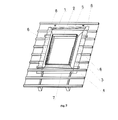
- fig. 2 shows the collar seated on the roof window frame and adjoining the sub-roofing structure
- fig. 3 presents the shape of the collar itself assumed after seating on the window frame
- fig. 4 shows the cross-section through the collar ready to be assembled, where the location of additional thermal insulation is shown.
- the top element 5 and the bottom element 7 parallel to battens 3 constitute flat strips with various widths, limited lengthwise with parallel flanks d and e , with various lengths but with a common axis of symmetry, while the shorter flanks consist of three segments, respectively a, b and c in element 5 and a, b and c' in element 7, in addition the extreme segments a and c and c ' are perpendicular to lengthwise flanks d and e and are connected with the oblique segment b .
- the segment a defines the height of the collar, adjoining the outer contour of the structure seated in the roof, and the segment c is longer than the segment c '.
- the side elements 6 of the roof 1, arranged perpendicularly to the battens 3, have the shape of an even-armed trapezoid.
- the shorter sides of elements 6 consist of segments a and b, identical to the segments a and b of elements 4 and 5.
- the side elements 6 have at their outer side a strip 8 made of a material with easily stretchable and at the same time water-tight structure.
- the elements 5, 6, 7 are permanently connected to each other along the segments a and b into a closed circuit.
- the angle between the oblique sides b and the sides d or e of the element 6 is known and depends on the corresponding angle in the elements 5 and 7 arranged in parallel to the battens 3 and is usually 45°.
- the insulation material may be any, advantageously porous, flexible and easily compressible structure with good thermal insulation properties.
- the following materials can be used: polyurethane foam PURS, impregnated with suspended acrylic, PE polyethylene foam, flexible PU polyurethane foam, PVC foam and also cellular rubber EPDM.
- This layer is rectangle shaped, in addition its longer side is common with the sides respectively d and d ' of elements 6, and 5 and 7 respectively.
- the shorter sides of the insulation layer 9 are limited advantageously by the segments a.
- the width of the layer 9 is so selected that it covers the whole part of collar intended for flanging with the length equal to the length of the segment a , and at least the same width on the surface adjacent to the roof.
- the flanging of the collar is enabled by a specific angular shape of the seam, consisting of segments a, b and c, connecting reciprocally cross-wise strips. To this end it is advantageous to shape the strips connected beforehand so that after their connection one element without any redundant material allowance is formed.
- the outer strip 8 as a rectangular element of easily stretched, water-tight and one-sided adhesive material, is permanently connected to the assembly of elements 5, 6 and 7 with the length equal to the total length of the collar 1.
- the outer strips 8 are arranged perpendicularly to the longitudinal direction of battens 3, symmetrically at the both sides of the collar 1. With respect to the shape of collar 1 they are arranged in parallel to the longer side of the side element 6. In the condition ready for assembly, fig. 2 and 3 , all collar elements 5, 6, 7, 8 are tightly connected to each other.
- the strip 8 width is selected so as to ensure its free shaping and tight securing to the ridge beam 3 and the insulating membrane 4 surface and is at least 200% of the ridge beam height.
- the strip 8 has at its inner side advantageously an adhesive layer protected for storage and transport, while at its outer side it has a layer of advantageously partially extendible foil or other material ensuring the tear resistance.
Landscapes
- Engineering & Computer Science (AREA)
- Architecture (AREA)
- Civil Engineering (AREA)
- Structural Engineering (AREA)
- Roof Covering Using Slabs Or Stiff Sheets (AREA)
Applications Claiming Priority (1)
| Application Number | Priority Date | Filing Date | Title |
|---|---|---|---|
| PL388685A PL234404B1 (pl) | 2009-07-31 | 2009-07-31 | Kołnierz uszczelniający łączący konstrukcję budowlaną przenikającą przez dach ze strukturą podpokryciową dachu |
Publications (2)
| Publication Number | Publication Date |
|---|---|
| EP2284329A2 true EP2284329A2 (de) | 2011-02-16 |
| EP2284329A3 EP2284329A3 (de) | 2013-03-27 |
Family
ID=42942046
Family Applications (1)
| Application Number | Title | Priority Date | Filing Date |
|---|---|---|---|
| EP10171486A Withdrawn EP2284329A3 (de) | 2009-07-31 | 2010-07-30 | Ein eine dachdurchdringende Konstruktion mit der Unterdachstruktur verbindender Kragen |
Country Status (2)
| Country | Link |
|---|---|
| EP (1) | EP2284329A3 (de) |
| PL (1) | PL234404B1 (de) |
Cited By (13)
| Publication number | Priority date | Publication date | Assignee | Title |
|---|---|---|---|---|
| CN102433966A (zh) * | 2011-08-26 | 2012-05-02 | 苏州多凯复合材料有限公司 | 压型板屋面开洞的防水结构 |
| EP2952646A1 (de) * | 2012-06-19 | 2015-12-09 | VKR Holding A/S | Unterdachkragen für ein dachfenster und verfahren zur montage eines dachfensters |
| EP3330452A1 (de) * | 2016-12-05 | 2018-06-06 | VKR Holding A/S | Dichtkragen zur montage um einen fensterrahmen, der in einem geneigten dach eines gebäudes montiert ist, und verfahren zur montage eines fensterrahmens |
| EP3404164A1 (de) * | 2017-05-16 | 2018-11-21 | VKR Holding A/S | Dichtmanschette |
| EP3404161A1 (de) * | 2017-05-16 | 2018-11-21 | VKR Holding A/S | Abdeckblechanordnung und verfahren zum witterungsschutz eines in einer schrägen dachfläche montierten dachfensters |
| EP3575509A1 (de) * | 2018-05-30 | 2019-12-04 | VKR Holding A/S | Verfahren zur bereitstellung einer montagehilfe, montagehilfe, die zur verwendung bei der montage eines fensterrahmens in einer dachkonstruktion eines gebäudes angepasst ist, und kit mit einer montagehilfe |
| EP3578727A1 (de) * | 2018-06-04 | 2019-12-11 | VKR Holding A/S | Installationshilfe zur verwendung bei der montage eines fensterrahmens in einer dachstruktur eines gebäudes, dichtungsmuffe und verfahren zur montage eines fensterrahmens |
| EP3885508A1 (de) | 2020-03-23 | 2021-09-29 | VKR Holding A/S | Verfahren zum anordnen eines unterdachkragens in installationsfertigem zustand, verpackter unterdachkragen und verfahren zur installation eines unterdachkragens |
| EP4023836A1 (de) | 2021-01-04 | 2022-07-06 | VKR Holding A/S | Verfahren zum verpacken eines unterdachkragens, verpackter unterdachkragen und faltwerkzeug zum falten eines unterdachkragens |
| DE202023102423U1 (de) | 2023-03-24 | 2023-09-18 | Vkr Holding A/S | Faltwerkzeug zum Falten einer Unterdachmanschette, verpackte Unterdachmanschette und Verwendung eines Faltwerkzeugs zum Falten einer Unterdachmanschette |
| WO2023186252A1 (en) | 2022-03-31 | 2023-10-05 | Vkr Holding A/S | An underroof collar, a kit including an underroof collar and a roof window, a mounted roof window, and a method for sealing the joint between a roof window and a roof structure |
| EP4417763A1 (de) | 2023-02-17 | 2024-08-21 | VKR Holding A/S | Satz von unterdachkragen und verfahren zum abdichten einer verbindung zwischen einer gruppe von dachfenstern, die in einer dachstruktur montiert sind, und einem unterdach |
| EP4417762A1 (de) | 2023-02-17 | 2024-08-21 | VKR Holding A/S | Wetterfeste anordnung zur verwendung mit einer gruppe von dachfenstern mit mindestens zwei dachfenstern und verfahren zur wetterfesten verbindung einer gruppe von dachfenstern |
Citations (4)
| Publication number | Priority date | Publication date | Assignee | Title |
|---|---|---|---|---|
| DE2554341B1 (de) | 1975-12-03 | 1977-06-08 | Braas & Co Gmbh | Vorrichtung zum abdichten der fuge zwischen einem dachfenster und den angrenzenden dacheindeckungsplatten |
| DE3442276A1 (de) | 1983-12-09 | 1985-06-13 | Peter W. 7290 Freudenstadt Barth | Unterverwahrung fuer dachfenster |
| WO1995028537A1 (en) | 1994-04-15 | 1995-10-26 | Polysheet A/S | A building element and a method of mounting a building element |
| WO1999002799A1 (en) | 1997-07-08 | 1999-01-21 | Velux Industri A/S | An attachment collar between a roof-penetrating building structure and an underroof |
Family Cites Families (5)
| Publication number | Priority date | Publication date | Assignee | Title |
|---|---|---|---|---|
| US4972638A (en) * | 1989-04-21 | 1990-11-27 | Rolscreen Company | Skylight flashing |
| DE9413970U1 (de) * | 1994-08-29 | 1996-01-04 | Klöber, Johannes, 58256 Ennepetal | Abdichtungs-Vorrichtung |
| DE29908614U1 (de) * | 1999-05-06 | 1999-09-30 | Ewald Dörken AG, 58313 Herdecke | Materialstreifen zum Anschließen eines flachen, ersten Dach-Bauelementes an einem zweiten Dach-Bauelement |
| DE10057774A1 (de) * | 2000-11-22 | 2002-10-10 | Kloeber Johannes | Anschlusschürze |
| DE202008014501U1 (de) * | 2008-10-31 | 2009-02-19 | Eisenhauer, Michael | Winkel-Eckmanschetten-Set, zur Außen- und Innen-Abdichtung für Schächte, Kanäle und Kamine |
-
2009
- 2009-07-31 PL PL388685A patent/PL234404B1/pl unknown
-
2010
- 2010-07-30 EP EP10171486A patent/EP2284329A3/de not_active Withdrawn
Patent Citations (4)
| Publication number | Priority date | Publication date | Assignee | Title |
|---|---|---|---|---|
| DE2554341B1 (de) | 1975-12-03 | 1977-06-08 | Braas & Co Gmbh | Vorrichtung zum abdichten der fuge zwischen einem dachfenster und den angrenzenden dacheindeckungsplatten |
| DE3442276A1 (de) | 1983-12-09 | 1985-06-13 | Peter W. 7290 Freudenstadt Barth | Unterverwahrung fuer dachfenster |
| WO1995028537A1 (en) | 1994-04-15 | 1995-10-26 | Polysheet A/S | A building element and a method of mounting a building element |
| WO1999002799A1 (en) | 1997-07-08 | 1999-01-21 | Velux Industri A/S | An attachment collar between a roof-penetrating building structure and an underroof |
Cited By (18)
| Publication number | Priority date | Publication date | Assignee | Title |
|---|---|---|---|---|
| CN102433966B (zh) * | 2011-08-26 | 2013-07-24 | 苏州多凯复合材料有限公司 | 压型板屋面开洞的防水结构 |
| CN102433966A (zh) * | 2011-08-26 | 2012-05-02 | 苏州多凯复合材料有限公司 | 压型板屋面开洞的防水结构 |
| EP2952646A1 (de) * | 2012-06-19 | 2015-12-09 | VKR Holding A/S | Unterdachkragen für ein dachfenster und verfahren zur montage eines dachfensters |
| EP3330452A1 (de) * | 2016-12-05 | 2018-06-06 | VKR Holding A/S | Dichtkragen zur montage um einen fensterrahmen, der in einem geneigten dach eines gebäudes montiert ist, und verfahren zur montage eines fensterrahmens |
| DK201670961A1 (en) * | 2016-12-05 | 2018-06-14 | Vkr Holding As | A sealing collar for being mounted around a window frame mounted in an inclined roof of a building, and a method for mounting a window frame |
| EP3725971A1 (de) | 2017-05-16 | 2020-10-21 | VKR Holding A/S | Unterdachmanschette zur verwendung für die wasserdichte verbindung zwischen einer dachstruktur und einem fensterrahmen, verpackte unterdachmanschette und verfahren zur bereitstellung einer unterdachmanschette |
| EP3404164A1 (de) * | 2017-05-16 | 2018-11-21 | VKR Holding A/S | Dichtmanschette |
| EP3404161A1 (de) * | 2017-05-16 | 2018-11-21 | VKR Holding A/S | Abdeckblechanordnung und verfahren zum witterungsschutz eines in einer schrägen dachfläche montierten dachfensters |
| WO2018210937A1 (en) | 2017-05-16 | 2018-11-22 | Vkr Holding A/S | An underroof collar for use in water-proofing the joint between a roof structure and a window frame, a packed underroof collar, and a method of providing an underroof collar |
| US10934717B2 (en) | 2017-05-16 | 2021-03-02 | Vkr Holding A/S | Underroof collar for use in water-proofing the joint between a roof structure and a window frame, a packed underroof collar, and a method of providing an underroof collar |
| EP3575509A1 (de) * | 2018-05-30 | 2019-12-04 | VKR Holding A/S | Verfahren zur bereitstellung einer montagehilfe, montagehilfe, die zur verwendung bei der montage eines fensterrahmens in einer dachkonstruktion eines gebäudes angepasst ist, und kit mit einer montagehilfe |
| EP3578727A1 (de) * | 2018-06-04 | 2019-12-11 | VKR Holding A/S | Installationshilfe zur verwendung bei der montage eines fensterrahmens in einer dachstruktur eines gebäudes, dichtungsmuffe und verfahren zur montage eines fensterrahmens |
| EP3885508A1 (de) | 2020-03-23 | 2021-09-29 | VKR Holding A/S | Verfahren zum anordnen eines unterdachkragens in installationsfertigem zustand, verpackter unterdachkragen und verfahren zur installation eines unterdachkragens |
| EP4023836A1 (de) | 2021-01-04 | 2022-07-06 | VKR Holding A/S | Verfahren zum verpacken eines unterdachkragens, verpackter unterdachkragen und faltwerkzeug zum falten eines unterdachkragens |
| WO2023186252A1 (en) | 2022-03-31 | 2023-10-05 | Vkr Holding A/S | An underroof collar, a kit including an underroof collar and a roof window, a mounted roof window, and a method for sealing the joint between a roof window and a roof structure |
| EP4417763A1 (de) | 2023-02-17 | 2024-08-21 | VKR Holding A/S | Satz von unterdachkragen und verfahren zum abdichten einer verbindung zwischen einer gruppe von dachfenstern, die in einer dachstruktur montiert sind, und einem unterdach |
| EP4417762A1 (de) | 2023-02-17 | 2024-08-21 | VKR Holding A/S | Wetterfeste anordnung zur verwendung mit einer gruppe von dachfenstern mit mindestens zwei dachfenstern und verfahren zur wetterfesten verbindung einer gruppe von dachfenstern |
| DE202023102423U1 (de) | 2023-03-24 | 2023-09-18 | Vkr Holding A/S | Faltwerkzeug zum Falten einer Unterdachmanschette, verpackte Unterdachmanschette und Verwendung eines Faltwerkzeugs zum Falten einer Unterdachmanschette |
Also Published As
| Publication number | Publication date |
|---|---|
| PL388685A1 (pl) | 2011-02-14 |
| PL234404B1 (pl) | 2020-02-28 |
| EP2284329A3 (de) | 2013-03-27 |
Similar Documents
| Publication | Publication Date | Title |
|---|---|---|
| EP2284329A2 (de) | Ein eine dachdurchdringende Konstruktion mit der Unterdachstruktur verbindender Kragen | |
| CA2136314C (en) | A sealing arrangement for windows, in particular roof windows | |
| EP2508690A1 (de) | Abdeckblech zur Versiegelung einer dachdurchdringenden Gebäudestruktur an die Unterdachstruktur | |
| JP4840539B2 (ja) | 屋根材付き太陽光発電パネル及び屋根材付き軒先材 | |
| US20100200037A1 (en) | Flexible dual skin wall and device for tensioning a dual skin flexible wall | |
| JPH01318646A (ja) | 屋根の棟を仕上げるために使用される封止ストリップ | |
| HU221068B1 (hu) | Plasztikusan kézzel formázható lefedõ anyag | |
| RU202143U1 (ru) | Кровельный фартук для трубы или канала | |
| HU222756B1 (hu) | Csatlakoztató lemezszerkezet tetőáttörésekhez, főleg tetőablakokhoz | |
| JP5683823B2 (ja) | 防湿カラー、防湿カラーを製造するための方法、防湿カラーの取り付けで使用するための工具、及び防湿カラーを取り付けるための方法 | |
| EP1896673B1 (de) | Kragen zum anschliessen eines dachdurchdringenden gebaüdeteiles an einem unterdach | |
| US5644882A (en) | Roofing system | |
| ES3051618T3 (en) | Building panel and coupling system for such building panels | |
| EP4499942A1 (de) | Unterdachkragen, kit mit einem unterdachkragen und dachfenster, montiertes dachfenster und verfahren zur abdichtung der verbindung zwischen einem dachfenster und einer dachstruktur | |
| JP3791965B2 (ja) | 陸屋根等における防水装置 | |
| JP2004300674A (ja) | 屋根用防水シート、及びこれを用いた防水施工方法 | |
| ES2525370T3 (es) | Tapajuntas para cubierta corrugada | |
| EP2623685A1 (de) | Isolier- und Dichtungsbahn | |
| JP4685592B2 (ja) | 防水構造 | |
| WO2007118258A3 (en) | Readily deployable light weight structures | |
| ES2771230T3 (es) | Remate inferior de alero para un tejado de tejas, procedimiento de colocación de dicho remate y tejado de construcción que comprende dicho remate | |
| JP3052904B2 (ja) | 断熱金属パネル | |
| CN221524028U (zh) | 一种屋面可滑移洞口支座 | |
| JP3602622B2 (ja) | 折版屋根構造 | |
| JP5144130B2 (ja) | シート状外囲体及びシート状外囲体の施工法 |
Legal Events
| Date | Code | Title | Description |
|---|---|---|---|
| PUAI | Public reference made under article 153(3) epc to a published international application that has entered the european phase |
Free format text: ORIGINAL CODE: 0009012 |
|
| 17P | Request for examination filed |
Effective date: 20100830 |
|
| AK | Designated contracting states |
Kind code of ref document: A2 Designated state(s): AL AT BE BG CH CY CZ DE DK EE ES FI FR GB GR HR HU IE IS IT LI LT LU LV MC MK MT NL NO PL PT RO SE SI SK SM TR |
|
| AX | Request for extension of the european patent |
Extension state: BA ME RS |
|
| PUAL | Search report despatched |
Free format text: ORIGINAL CODE: 0009013 |
|
| AK | Designated contracting states |
Kind code of ref document: A3 Designated state(s): AL AT BE BG CH CY CZ DE DK EE ES FI FR GB GR HR HU IE IS IT LI LT LU LV MC MK MT NL NO PL PT RO SE SI SK SM TR |
|
| AX | Request for extension of the european patent |
Extension state: BA ME RS |
|
| RIC1 | Information provided on ipc code assigned before grant |
Ipc: E04D 13/03 20060101AFI20130219BHEP Ipc: E04D 13/147 20060101ALI20130219BHEP |
|
| STAA | Information on the status of an ep patent application or granted ep patent |
Free format text: STATUS: THE APPLICATION IS DEEMED TO BE WITHDRAWN |
|
| 18D | Application deemed to be withdrawn |
Effective date: 20130928 |