EP2284350A2 - Schwelle eines Schiebeverschlussflügels, mit thermischer Trennung und versteckter Drainage - Google Patents
Schwelle eines Schiebeverschlussflügels, mit thermischer Trennung und versteckter Drainage Download PDFInfo
- Publication number
- EP2284350A2 EP2284350A2 EP10170422A EP10170422A EP2284350A2 EP 2284350 A2 EP2284350 A2 EP 2284350A2 EP 10170422 A EP10170422 A EP 10170422A EP 10170422 A EP10170422 A EP 10170422A EP 2284350 A2 EP2284350 A2 EP 2284350A2
- Authority
- EP
- European Patent Office
- Prior art keywords
- profile
- runoff
- heat shield
- threshold
- rails
- Prior art date
- Legal status (The legal status is an assumption and is not a legal conclusion. Google has not performed a legal analysis and makes no representation as to the accuracy of the status listed.)
- Granted
Links
Images


Classifications
-
- E—FIXED CONSTRUCTIONS
- E06—DOORS, WINDOWS, SHUTTERS, OR ROLLER BLINDS IN GENERAL; LADDERS
- E06B—FIXED OR MOVABLE CLOSURES FOR OPENINGS IN BUILDINGS, VEHICLES, FENCES OR LIKE ENCLOSURES IN GENERAL, e.g. DOORS, WINDOWS, BLINDS, GATES
- E06B7/00—Special arrangements or measures in connection with doors or windows
- E06B7/14—Measures for draining-off condensed water or water leaking-in frame members for draining off condensation water, throats at the bottom of a sash
-
- E—FIXED CONSTRUCTIONS
- E06—DOORS, WINDOWS, SHUTTERS, OR ROLLER BLINDS IN GENERAL; LADDERS
- E06B—FIXED OR MOVABLE CLOSURES FOR OPENINGS IN BUILDINGS, VEHICLES, FENCES OR LIKE ENCLOSURES IN GENERAL, e.g. DOORS, WINDOWS, BLINDS, GATES
- E06B3/00—Window sashes, door leaves, or like elements for closing wall or like openings; Layout of fixed or moving closures, e.g. windows in wall or like openings; Features of rigidly-mounted outer frames relating to the mounting of wing frames
- E06B3/04—Wing frames not characterised by the manner of movement
- E06B3/263—Frames with special provision for insulation
- E06B3/26347—Frames with special provision for insulation specially adapted for sliding doors or windows
-
- E—FIXED CONSTRUCTIONS
- E06—DOORS, WINDOWS, SHUTTERS, OR ROLLER BLINDS IN GENERAL; LADDERS
- E06B—FIXED OR MOVABLE CLOSURES FOR OPENINGS IN BUILDINGS, VEHICLES, FENCES OR LIKE ENCLOSURES IN GENERAL, e.g. DOORS, WINDOWS, BLINDS, GATES
- E06B3/00—Window sashes, door leaves, or like elements for closing wall or like openings; Layout of fixed or moving closures, e.g. windows in wall or like openings; Features of rigidly-mounted outer frames relating to the mounting of wing frames
- E06B3/04—Wing frames not characterised by the manner of movement
- E06B3/263—Frames with special provision for insulation
- E06B3/2632—Frames with special provision for insulation with arrangements reducing the heat transmission, other than an interruption in a metal section
- E06B2003/26325—Frames with special provision for insulation with arrangements reducing the heat transmission, other than an interruption in a metal section the convection or radiation in a hollow space being reduced, e.g. by subdividing the hollow space
- E06B2003/2633—Frames with special provision for insulation with arrangements reducing the heat transmission, other than an interruption in a metal section the convection or radiation in a hollow space being reduced, e.g. by subdividing the hollow space the insulating strips between the metal sections having ribs extending into the hollow space
Definitions
- a sliding frame with a profile forming a heat shield is known from the document EP 1 783 312 .
- the heat shield function is provided by an insulating element disposed between the branches of a U-shaped section.
- this document which relates to an application by mounting such a structure, does not deal with the problem of drainage of the sliding closure frame threshold.
- EP 0 495 682 which relates to a sliding threshold having a brush-like structure disposed between the sliding rails or the like.
- Such a type of brush has the disadvantage of being poor thermal insulation and not easy maintenance.
- a sliding frame threshold comprises a metal section on which a generally U-shaped thermal insulating section is mounted between the two rails.
- This U-shaped insulating profile comprises runoff evacuation openings, generally located at the base of the lateral branches of the U; after having passed through these evacuation openings of the insulating section, the water is also drained by openings, made through the side walls of the outboard metal profile outwardly, possibly with discharge nozzles placed on the outer face of the metal section to slow down the air inlet and the discharge of the evacuated water.
- This type of sliding sill threshold evacuation is apparent and therefore unsightly.
- this type of evacuation has the disadvantage of offering only a minimal resistance to the discharge pressure from the outside wind.
- the invention aims to overcome these disadvantages.
- the invention aims to provide a threshold having heat shield functions and evacuation invisible or at least completely discrete.
- the invention has a number of advantages over the state of the art.
- the runoff profile completing the heat shield profile constitutes a continuous longitudinal opening and yet discrete discharge of runoff water that arrives on the shield.
- the continuity of this longitudinal opening allows to confer a discretion of the evacuation allied to the search for a certain aesthetics.
- this arrangement does not affect the thermal insulation insofar as the longitudinal opening is only of small transverse dimension.
- the standard allows up to 2 mm gap, the heat flow is not high enough to affect the thermal insulation function.
- runoff outlets are made in the heat shield insulating profile, so that they are not visible when the runoff profile is placed on the heat shield insulating profile. Then, evacuation openings are made in the support profile in a conventional manner through its side walls or on horizontal webs of this profile so as not to reveal an opening in the visible face.
- Another advantage of the solution of the invention consists in recovering the total volume of the central longitudinal housing for collecting runoff from the heat shield, under the runoff profile, for the storage of runoff water, because the longitudinal opening allows a water evacuation almost without resistance, which prevents this water to stagnate above the surface of the runoff profile waiting to be evacuated through openings of smaller passage sections. This is the amount of water acceptable by the overflow profile above the rails.
- Another advantage of the invention consists in reducing the "bubbling" (reflux pressure of the discharged water, against the pressure of the outside wind which may tend to prevent this evacuation by gravity), thanks to an advantageous arrangement of the holes on a horizontal surface involving the possibility of forming baffles, whereas in the state of the art, the evacuation by the side walls implies being in direct line with the external holes in the wind.
- said heat shield profile mounted between the two rails has a generally U-shaped section open towards the outside to form a longitudinal central recess U, for collecting runoff water.
- open outward is meant an open section on the opposite side to the support profile, that is, the U is open towards the sliding closure frame.
- said runoff profile and said heat shield profile form two distinct profiles dissociated associated with each other by means of removable connection means of the clipping type.
- the solution of making the two profiles of runoff and heat shield in two separate sections allows for these two profiles in different materials: insulation for the heat shield profile and for example metal for the runoff profile, without damaging the thermal insulation because the distance according to the invention between the runoff profile and the profile which faces it avoids that a thermal bridge is formed.
- the metallic realization of the runoff profile allows to offer new aesthetics of the threshold (concealed drainage and aesthetic agreement with the main metal threshold profile) without harming the thermal insulation.
- said runoff profile and said heat shield profile form a single profile in one piece made of insulating material.
- said hood is coated with a layer of a material different from that constituting said flow profile.
- This feature makes it possible to use the same material for the runoff profile and the heat shield while giving the appearance of the runoff profile of another constituent material.
- said runoff profile and said heat shield profile forming a single piece of single piece made of insulating material are associated by a connection to a degree of freedom in longitudinal rotation, combined with additional means fixing one profile on the other.
- This feature offers the advantages of two separate profiles to facilitate manufacturing, including the realization of drainage openings, while also offering the advantages of a profile made in one piece, especially in terms of assembly and logistics without having the disadvantages in terms of manufacturing.
- said runoff profile and said heat shield profile form a single piece made of insulating material integrally, the profiled runoff portion being fixed relative to the profiled portion forming a heat shield.
- said runoff section has a generally T-shaped section, the edge of the vertical portion provides the connection with the heat shield profile and the horizontal portion ensures the reception of runoff.
- the T-shaped section of the flow profile may be double vertical bar.
- the longitudinal edge of said hood may face a longitudinal wall of the support profile or a longitudinal wall of the heat shield profile.
- each of the longitudinal edges of said cover extends at a distance from the profile which faces it.
- the upper surface of said hood formed by said runoff profile is located substantially at the base of two inner walls of the two metal rails, facing each other, the upper part of the rails being projecting above the upper surface of said hood.
- This characteristic makes it possible to optimize the threshold space reserved for runoff water and the space of the said threshold reserved for the lower part of the sliding openings, in the presence of the runoff profile.
- a support section 1 with a thermal break of known type constituted in the example of two metal rails 2 for sliding sliding frames, these rails being assembled by means of a complete connection, for example by crimping, by two intermediate bars 3 made of insulating material, for example a plastics material of polyamide type or the like.
- the support profile 1 here has a generally U-shaped section in any known manner.
- the bars 3 form webs 4 perpendicular to the connecting webs even with the rails 2, limiting the heat exchange by convection, between the outer and inner media, separated by the sliding frame.
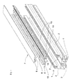
- a profile 5 forming a heat shield is clipped between the rails 2 of the support profile 1, as more particularly shown in FIG. figure 4 for the example, to form a longitudinal central recess U, for collecting runoff water, whose vertical or substantially vertical branches define vertical or substantially vertical walls in the example aligned between the branches of the U of the section 5 and the inner walls vis-à-vis the metal rails 2.
- the profile 5 is made of insulating material, for example a polyamide type plastic or the like.
- the bottom of the U of the profile 5 advantageously comprises on its horizontal surface drainage holes 6 whose function will be described below.
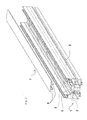
- the figure 2 shows the profiles 1 and 5 assembled.
- the profile 7 When the profile 7 is mounted on the profile 5, the profile 7 thus hides the drainage holes 6 as shown in FIG. figure 3 .
- the runoff profile 7 and the heat shield profile 5 advantageously form two distinct profiles dissociated associated with each other by means of removable connection means of the clipping type.
- the drainage orifices 6 are arranged on either side of the rib 9 and also on either side of the vertical bars 8 of the flow profile 7.
- the drainage orifices 6 each adopt a length and are distributed along the section 5, according to standards and needs.
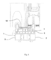
- the horizontal bar of the T formed by the section of the flow profile 7 has a width such that the two opposite transverse edges of the plate 10 extending longitudinally and forming the upper part of the profile 7, extend at a distance e, for example, preferably between 1 mm and 2 mm, from the flange of the U-profile 5 or the rail 2 facing them, here in the example at the boundary between the rails 2 and the profile 5, thus defining a longitudinal interval 11 for discharging the runoff water that ends on the plate 10.
- the distance e may be equal or substantially equal on each side of the plate 10 or different.
- the plate 10 may for example be convex according to its transverse profile, the convexity being turned upwards, as shown in the figures, in order to facilitate the flow of water towards the longitudinal openings thus formed between the edges of the plate 10 and the rails 2 and / or the U-shaped section 5.
- the interval 11 thus formed ( figures 3 or 4 ) forming said two longitudinal discharge openings, allows the flow of runoff under the section 7, more precisely under the plate 10 of this, then, through the drainage holes 6 of the profile 5 advantageously formed on the horizontal surface of this profile 5 and under the plate 10, under the U-shaped base of the profile 5 to the profile 1 from which they are then removed outwardly in the usual way (not shown) through its side walls of the support profile 1.
- Openings 12 are made in the case in point, advantageously in vertical ribs 13 formed under the U-section of the section 5, as shown, between the base thereof and the bottom of the U of the section 1 to create a passage for the water below the drainage holes 6 to conventional openings (not shown) made in the section 1 so that finally the water is rejected in front.
- the openings 12 and the drainage holes 6 may advantageously be offset longitudinally to participate advantageously in the constitution of flow baffles.
- the U-profile comprises in the example two other longitudinal vertical ribs 14 parallel to the two ribs 13 and placed between them, whose function in the example is to form a support of the profile 5 on the profile 1, more precisely and advantageously on the insulating strips 3.
- These longitudinal ribs 14 preferably comprise openings 15 distributed along them, like those of the ribs 13, and aligned longitudinally or offset with them, to ensure a path of the evacuation of water from one rail 2 to the other on the bottom of the U.
- the openings 12 and 15 are made by means of indentations of the lower edge of the corresponding ribs 13 and 14 respectively, so that the water can travel on the bottom of the U of the profile 1. It should be noted that the lower edge of the ribs 13 may not be in contact with the bottom of the U of the profile 1 as shown on the figure 4 .
- Such a flow of water through the drain holes 6 and described flow openings 12 forms a set of baffles on a horizontal path and on a combined vertical path of water, advantageously reducing the "bubbling" pressure as explained above.
- the second exemplary embodiment of a threshold according to the invention will now be described with the help of the figure 5 .
- the example of figure 5 is similar to the first embodiment of the Figures 1 to 4 , except for the plate 10 which is here coated with a layer 20 of a material different from that constituting the flow profile 7.
- This layer 20 covers the visible upper surface of the plate 10, as shown.
- the layer 20 furthermore acts as a hubcap and can be made for example in the form of a metal sheet in the form of a longitudinal strip of convex cross-section, the two longitudinal edges of which are curved so as to form longitudinal retention hooks.
- the runoff profile 7 may advantageously be made of plastic material.
- the convexity of the sheet forming the layer 20 is rotated in a manner similar to the convexity of the plate 10 of the first example.
- the expensive and thermally conductive material is reduced to a sheet of minimum thickness as needed.
- the distance e is no longer measured from the transverse edges of the plate 10 as for the first example, but from the transverse edges of the layer 20.
- the layer 20 can be manufactured to be associated, by removably example, the runoff profile 7 by longitudinal sliding, the visible upper surface of the layer 20 constituting the drainage water runoff surface on the runoff profile.
- the third exemplary embodiment of a threshold according to the invention will now be described with the help of the figure 6 .
- elements identical or similar, at least functionally, to those of the first and second examples have respectively the same references.
- the example of figure 6 is similar to the second embodiment according to the figure 5 , with the exception of the runoff profile 7 and the heat shield profile 5 which form in this example a single profile integral (monobloc) made of insulating material.
- the runoff profile 7 or runoff portion of the single profile, and the profile 5 or heat shield portion of the single profile are associated by a link with a degree of freedom in longitudinal rotation, combined with additional means for fixing the profile. one profile on the other.
- One of the transverse edges of the plate 10 is connected, in the region of the end of the edge advantageously located on the lower surface of the plate 10, to the part facing the heat shield section 5, for example the upper region of a branch of the U, by a web 21 of flexible material, thin, which advantageously extends along the length of the profile 5, 7 monobloc, to form a hinge pivoting or articulation, along a longitudinal axis of the runoff portion 7 with respect to the heat shield portion 5.
- the trickle portion 7 is fixed, after pivoting, to the heat shield part 5, like the first and second embodiments, for example by clipping via the lower edge of at least one of the two vertical bars 8 of the T which cooperates with the rib 9 formed at the bottom of the profile 5 and placed in the example between the two vertical bars 8, preferably the bar 8 farthest from the web 21 as shown on the figure 6 .
- the fastening of the web 21 on the lower surface of the plate 10 is made such that this fastening advantageously allows the sliding of the sheet 20 on the runoff portion 7, as in the example of the figure 5 .
- the sail 21 may be longitudinally interrupted at several points (not shown) to ensure the flow of runoff through it; the sail 21 may also consist of a plurality of fine links distributed along the runoff profile so that the longitudinal opening is preponderant in front of the space occupied by the links.
- FIG. 7 The fourth exemplary embodiment of a threshold according to the invention will now be described with the help of the figure 7 .
- the elements that are identical or similar, at least functionally, to those of the other examples respectively have the same references.
- the example of figure 7 is similar to the third exemplary embodiment according to the figure 6 with the exception of layer 20 which is absent; the convex transverse section of the plate 10 is similar to that of the first example according to the Figures 1 to 4 .
- the runoff profile 7 and the heat shield profile 5 form a single profile in one piece made of insulating material.
- the runoff profile 7 and the heat shield profile 5 form an integral profile made of insulating material in a single piece, the runoff profile 7 or runoff portion being fixed relative to the profile 5 forming heat shield or heat shield part of the monobloc profile.
- the single piece profile takes the form of a tubular section, preferably honeycomb, made of substantially rigid plastic material.
- the profile 5, 7 insulating monoblock is substantially indeformable according to normal forces applicable to it in normal use.
- the profile 5, 7 insulating monoblock is slid longitudinally into the U of the support profile 1.
- the heat shield portion 5 adopts a U-shaped surmounted by the portion 7 of runoff attached to the base of the U, in the example by three vertical ribs .
- the runoff portion comprises a convex upper plate 10 like the other described embodiments.
- the single profile 5, 7 monobloc insulation is wedged between the rails 2 by the base of the U of the shield portion 5 which is adjusted between the two vertical walls of the rails of the U formed by the support profile 1.
- the base of the heat shield shaped of U adopts the shape of a flat plate dimple which marries the surface of the U base formed by the support section 1 straddling the thermally insulating bars so as to cover them.
- the vertical or substantially vertical branches of the U formed by the heat shield portion 5 extend to come close to or in contact with the return walls of the rails toward the inside of the U, as shown.
- the upper surface of the plate 10 of the flow profile 7 is advantageously and substantially at the level of the base of the inner walls vis-à-vis the metal rails 2, as shown in FIGS. Figures 3 to 8 , the upper part of the rails 2 being protruding above the hood formed by the runoff profile.
- This remaining U-shaped space has the function of allowing, in a known manner, the positioning inside this space, of the base of the sliding openings, carrying the friction brushes against the inner walls opposite the rails, as represented on the figures 5 , 7 , and 8 .
- the set of threshold structure thus arranged and described above makes it possible to provide a thermal break threshold for sliding openings mounted on projecting rails, whose thermal insulation performance is very good, combined with a drainage system. hidden runoff and various aesthetic possibilities of the threshold.
Landscapes
- Engineering & Computer Science (AREA)
- Civil Engineering (AREA)
- Structural Engineering (AREA)
- Building Environments (AREA)
- Sewage (AREA)
Priority Applications (2)
| Application Number | Priority Date | Filing Date | Title |
|---|---|---|---|
| SI201030896T SI2284350T1 (sl) | 2009-07-31 | 2010-07-22 | Prag drsnega zapornega okvirja, ki vsebuje toplotni ščit in skrito drenažo |
| PL10170422T PL2284350T3 (pl) | 2009-07-31 | 2010-07-22 | Próg ramy przesuwnego zamknięcia zawierający osłonę termiczną i ukryte odwodnienie |
Applications Claiming Priority (1)
| Application Number | Priority Date | Filing Date | Title |
|---|---|---|---|
| FR0955419A FR2948723B1 (fr) | 2009-07-31 | 2009-07-31 | Dispositif de drainage pour seuil de chassis de fermeture coulissant |
Publications (3)
| Publication Number | Publication Date |
|---|---|
| EP2284350A2 true EP2284350A2 (de) | 2011-02-16 |
| EP2284350A3 EP2284350A3 (de) | 2012-01-04 |
| EP2284350B1 EP2284350B1 (de) | 2014-12-17 |
Family
ID=42017387
Family Applications (1)
| Application Number | Title | Priority Date | Filing Date |
|---|---|---|---|
| EP10170422.9A Active EP2284350B1 (de) | 2009-07-31 | 2010-07-22 | Schwelle eines Schiebeverschlussflügels, mit thermischer Trennung und versteckter Drainage |
Country Status (6)
| Country | Link |
|---|---|
| EP (1) | EP2284350B1 (de) |
| ES (1) | ES2533083T3 (de) |
| FR (1) | FR2948723B1 (de) |
| PL (1) | PL2284350T3 (de) |
| PT (1) | PT2284350E (de) |
| SI (1) | SI2284350T1 (de) |
Cited By (2)
| Publication number | Priority date | Publication date | Assignee | Title |
|---|---|---|---|---|
| BE1026181B1 (nl) * | 2018-04-05 | 2019-11-04 | Veranco Nv | Schuifdeursysteem voor een veranda of terras |
| US11346147B2 (en) | 2020-10-01 | 2022-05-31 | Solar Innovations Llc | Modular sill |
Families Citing this family (3)
| Publication number | Priority date | Publication date | Assignee | Title |
|---|---|---|---|---|
| FR2988125B1 (fr) * | 2012-03-13 | 2014-11-21 | Socredis | Seuil non-encastrable pour personnes a mobilite reduite pour chassis dormant a ouvrants coulissants |
| CN103758438A (zh) * | 2013-12-25 | 2014-04-30 | 泰诺风保泰(苏州)隔热材料有限公司 | 一种建筑用节能门窗复合型材及其制造方法 |
| ES2935232B2 (es) * | 2021-09-02 | 2023-10-11 | Exlabesa Building Systems S A U | Sistema de rodamientos para corredera |
Citations (3)
| Publication number | Priority date | Publication date | Assignee | Title |
|---|---|---|---|---|
| EP0495682A2 (de) | 1991-01-17 | 1992-07-22 | Marvin Lumber And Cedar Co. | Schwellenkonstruktion für Schiebetür |
| US20030177699A1 (en) | 2000-12-01 | 2003-09-25 | Tateyama Aluminum Industry Co., Ltd. | Outdoor window |
| EP1783312A1 (de) | 2005-11-04 | 2007-05-09 | NORSK HYDRO a.s.a. | Schiebetür |
Family Cites Families (5)
| Publication number | Priority date | Publication date | Assignee | Title |
|---|---|---|---|---|
| DE2143698A1 (de) * | 1971-09-01 | 1973-07-26 | Dynamit Nobel Ag | Stranggepresste profile, vorzugsweise aus einem thermoplastischen kunststoff, fuer blendrahmen und fluegelrahmen von schiebefenstern, schiebetueren o.dgl |
| KR20060040036A (ko) * | 2004-11-04 | 2006-05-10 | 남창드림윈도스 주식회사 | 시스템 창호의 조립식 창틀구조 |
| DE102006045173A1 (de) * | 2006-09-25 | 2008-04-03 | Gerd Philippi | Unteres Führungsprofil für ein Schiebefenster |
| ITBO20070242A1 (it) * | 2007-04-03 | 2008-10-04 | Gsg Int Spa | Profilato per serramenti scorrevoli, metodo per la realizzazione del profilato, e serramento ottenuto con il profilato stesso. |
| KR100914756B1 (ko) * | 2009-03-02 | 2009-08-31 | 김순석 | 시공이 용이한 창호장치 |
-
2009
- 2009-07-31 FR FR0955419A patent/FR2948723B1/fr not_active Expired - Fee Related
-
2010
- 2010-07-22 EP EP10170422.9A patent/EP2284350B1/de active Active
- 2010-07-22 SI SI201030896T patent/SI2284350T1/sl unknown
- 2010-07-22 ES ES10170422.9T patent/ES2533083T3/es active Active
- 2010-07-22 PL PL10170422T patent/PL2284350T3/pl unknown
- 2010-07-22 PT PT10170422T patent/PT2284350E/pt unknown
Patent Citations (3)
| Publication number | Priority date | Publication date | Assignee | Title |
|---|---|---|---|---|
| EP0495682A2 (de) | 1991-01-17 | 1992-07-22 | Marvin Lumber And Cedar Co. | Schwellenkonstruktion für Schiebetür |
| US20030177699A1 (en) | 2000-12-01 | 2003-09-25 | Tateyama Aluminum Industry Co., Ltd. | Outdoor window |
| EP1783312A1 (de) | 2005-11-04 | 2007-05-09 | NORSK HYDRO a.s.a. | Schiebetür |
Cited By (3)
| Publication number | Priority date | Publication date | Assignee | Title |
|---|---|---|---|---|
| BE1026181B1 (nl) * | 2018-04-05 | 2019-11-04 | Veranco Nv | Schuifdeursysteem voor een veranda of terras |
| US11346147B2 (en) | 2020-10-01 | 2022-05-31 | Solar Innovations Llc | Modular sill |
| US11846134B2 (en) | 2020-10-01 | 2023-12-19 | Solar Innovations Llc | Modular sill |
Also Published As
| Publication number | Publication date |
|---|---|
| ES2533083T3 (es) | 2015-04-07 |
| FR2948723A1 (fr) | 2011-02-04 |
| FR2948723B1 (fr) | 2015-03-13 |
| SI2284350T1 (sl) | 2015-07-31 |
| EP2284350A3 (de) | 2012-01-04 |
| PT2284350E (pt) | 2015-03-31 |
| EP2284350B1 (de) | 2014-12-17 |
| PL2284350T3 (pl) | 2015-08-31 |
Similar Documents
| Publication | Publication Date | Title |
|---|---|---|
| EP2284350B1 (de) | Schwelle eines Schiebeverschlussflügels, mit thermischer Trennung und versteckter Drainage | |
| EP2078817A1 (de) | Isolierprofil für Öffnungsflügel mit Schiebeöffnung, Bauprofil und Öffnungsflügel, der ein solches Isolierprofil umfasst | |
| FR2920729A1 (fr) | Balai d'essuyage a projection de liquide pour vitres de vehicule | |
| EP2354717A2 (de) | Befestigungsstruktur für Sonnenkollektoren | |
| EP3115525B1 (de) | Verstellbare und isolierende blende für eine sonnenschutzanlage | |
| WO2015015119A1 (fr) | Vitrage a joint profile et enjoliveur, enjoliveur et procede de fabrication du vitrage | |
| EP2050916A2 (de) | Isolierter Klappladen | |
| EP0559292A1 (de) | Anschlusselement für Bauprofile und Konstruktionen, die mittels solcher Anschlusselemente verbundene Bauprofile enthalten | |
| EP1783312B1 (de) | Schiebetür | |
| FR2981976A1 (fr) | Fermeture coulissante de baie de construction | |
| FR2650638A1 (fr) | Dispositif pour la liaison de panneaux d'habillage de parois | |
| FR2554862A1 (fr) | Chassis pour cadre de fenetre, constitue de plusieurs elements modulaires | |
| EP1024232A1 (de) | Deckenplatte | |
| EP1558825B1 (de) | Komposit-unterdecke mit aufgespannter leinwand | |
| FR2951492A1 (fr) | Corps de coffre de volet roulant et dispositif de coffre comprenant un tel corps | |
| FR2850423A1 (fr) | Dispositif de joint pour systeme de fermeture de baie a au moins un vantail coulissant | |
| FR2531137A3 (fr) | Rideau de protection avec lattes metalliques accouplees a des coques exterieures en matiere plastique | |
| FR2934310A1 (fr) | Volet roulant en applique | |
| EP2261452B1 (de) | Verschlussrahmen vom Typ Schiebeelement oder Ähnliches | |
| FR3003291A1 (fr) | Seuil non-encastrable pour personnes a mobilite reduite pour chassis dormant a ouvrants coulissants | |
| FR2877985A1 (fr) | Joue pour coffre de volet et coffre comprenant au moins deux joues | |
| EP2461996B1 (de) | Dichtung für kfz-fensterschacht und kfz-tür ausgestattet mit solch einer dichtung | |
| FR2951769A1 (fr) | Montant d'element coulissant de fermeture de batiment | |
| FR3073246A1 (fr) | Profile de rupture de pont thermique pour menuiserie de type porte ou fenetre et menuiserie equipee d'un tel profile | |
| EP1700992A1 (de) | Belüfteter Fenster, Fenstertür oder dergleiche, mit einer Fluidverbindung eines Luftspaltes mit der Aussenumgebung mittels einer profilierten Dichtung im unteren Querbereich des Aussenglases. |
Legal Events
| Date | Code | Title | Description |
|---|---|---|---|
| PUAI | Public reference made under article 153(3) epc to a published international application that has entered the european phase |
Free format text: ORIGINAL CODE: 0009012 |
|
| AK | Designated contracting states |
Kind code of ref document: A2 Designated state(s): AL AT BE BG CH CY CZ DE DK EE ES FI FR GB GR HR HU IE IS IT LI LT LU LV MC MK MT NL NO PL PT RO SE SI SK SM TR |
|
| AX | Request for extension of the european patent |
Extension state: BA ME RS |
|
| PUAL | Search report despatched |
Free format text: ORIGINAL CODE: 0009013 |
|
| AK | Designated contracting states |
Kind code of ref document: A3 Designated state(s): AL AT BE BG CH CY CZ DE DK EE ES FI FR GB GR HR HU IE IS IT LI LT LU LV MC MK MT NL NO PL PT RO SE SI SK SM TR |
|
| AX | Request for extension of the european patent |
Extension state: BA ME RS |
|
| RIC1 | Information provided on ipc code assigned before grant |
Ipc: E06B 3/263 20060101ALI20111128BHEP Ipc: E06B 7/14 20060101AFI20111128BHEP |
|
| 17P | Request for examination filed |
Effective date: 20120618 |
|
| GRAP | Despatch of communication of intention to grant a patent |
Free format text: ORIGINAL CODE: EPIDOSNIGR1 |
|
| GRAJ | Information related to disapproval of communication of intention to grant by the applicant or resumption of examination proceedings by the epo deleted |
Free format text: ORIGINAL CODE: EPIDOSDIGR1 |
|
| GRAP | Despatch of communication of intention to grant a patent |
Free format text: ORIGINAL CODE: EPIDOSNIGR1 |
|
| GRAP | Despatch of communication of intention to grant a patent |
Free format text: ORIGINAL CODE: EPIDOSNIGR1 |
|
| INTG | Intention to grant announced |
Effective date: 20140519 |
|
| INTG | Intention to grant announced |
Effective date: 20140530 |
|
| RAP1 | Party data changed (applicant data changed or rights of an application transferred) |
Owner name: SAPA AS |
|
| GRAS | Grant fee paid |
Free format text: ORIGINAL CODE: EPIDOSNIGR3 |
|
| GRAA | (expected) grant |
Free format text: ORIGINAL CODE: 0009210 |
|
| AK | Designated contracting states |
Kind code of ref document: B1 Designated state(s): AL AT BE BG CH CY CZ DE DK EE ES FI FR GB GR HR HU IE IS IT LI LT LU LV MC MK MT NL NO PL PT RO SE SI SK SM TR |
|
| REG | Reference to a national code |
Ref country code: GB Ref legal event code: FG4D Free format text: NOT ENGLISH |
|
| REG | Reference to a national code |
Ref country code: CH Ref legal event code: EP |
|
| REG | Reference to a national code |
Ref country code: IE Ref legal event code: FG4D Free format text: LANGUAGE OF EP DOCUMENT: FRENCH |
|
| REG | Reference to a national code |
Ref country code: AT Ref legal event code: REF Ref document number: 702078 Country of ref document: AT Kind code of ref document: T Effective date: 20150115 |
|
| REG | Reference to a national code |
Ref country code: DE Ref legal event code: R096 Ref document number: 602010021001 Country of ref document: DE Effective date: 20150129 |
|
| REG | Reference to a national code |
Ref country code: NL Ref legal event code: T3 |
|
| REG | Reference to a national code |
Ref country code: PT Ref legal event code: SC4A Free format text: AVAILABILITY OF NATIONAL TRANSLATION Effective date: 20150316 |
|
| REG | Reference to a national code |
Ref country code: SE Ref legal event code: TRGR Ref country code: ES Ref legal event code: FG2A Ref document number: 2533083 Country of ref document: ES Kind code of ref document: T3 Effective date: 20150407 |
|
| PG25 | Lapsed in a contracting state [announced via postgrant information from national office to epo] |
Ref country code: FI Free format text: LAPSE BECAUSE OF FAILURE TO SUBMIT A TRANSLATION OF THE DESCRIPTION OR TO PAY THE FEE WITHIN THE PRESCRIBED TIME-LIMIT Effective date: 20141217 Ref country code: LT Free format text: LAPSE BECAUSE OF FAILURE TO SUBMIT A TRANSLATION OF THE DESCRIPTION OR TO PAY THE FEE WITHIN THE PRESCRIBED TIME-LIMIT Effective date: 20141217 |
|
| REG | Reference to a national code |
Ref country code: FR Ref legal event code: PLFP Year of fee payment: 6 |
|
| REG | Reference to a national code |
Ref country code: LT Ref legal event code: MG4D |
|
| PG25 | Lapsed in a contracting state [announced via postgrant information from national office to epo] |
Ref country code: LV Free format text: LAPSE BECAUSE OF FAILURE TO SUBMIT A TRANSLATION OF THE DESCRIPTION OR TO PAY THE FEE WITHIN THE PRESCRIBED TIME-LIMIT Effective date: 20141217 Ref country code: HR Free format text: LAPSE BECAUSE OF FAILURE TO SUBMIT A TRANSLATION OF THE DESCRIPTION OR TO PAY THE FEE WITHIN THE PRESCRIBED TIME-LIMIT Effective date: 20141217 Ref country code: GR Free format text: LAPSE BECAUSE OF FAILURE TO SUBMIT A TRANSLATION OF THE DESCRIPTION OR TO PAY THE FEE WITHIN THE PRESCRIBED TIME-LIMIT Effective date: 20150318 |
|
| REG | Reference to a national code |
Ref country code: NO Ref legal event code: T2 Effective date: 20141217 |
|
| PG25 | Lapsed in a contracting state [announced via postgrant information from national office to epo] |
Ref country code: RO Free format text: LAPSE BECAUSE OF FAILURE TO SUBMIT A TRANSLATION OF THE DESCRIPTION OR TO PAY THE FEE WITHIN THE PRESCRIBED TIME-LIMIT Effective date: 20141217 Ref country code: SK Free format text: LAPSE BECAUSE OF FAILURE TO SUBMIT A TRANSLATION OF THE DESCRIPTION OR TO PAY THE FEE WITHIN THE PRESCRIBED TIME-LIMIT Effective date: 20141217 Ref country code: EE Free format text: LAPSE BECAUSE OF FAILURE TO SUBMIT A TRANSLATION OF THE DESCRIPTION OR TO PAY THE FEE WITHIN THE PRESCRIBED TIME-LIMIT Effective date: 20141217 |
|
| PG25 | Lapsed in a contracting state [announced via postgrant information from national office to epo] |
Ref country code: IS Free format text: LAPSE BECAUSE OF FAILURE TO SUBMIT A TRANSLATION OF THE DESCRIPTION OR TO PAY THE FEE WITHIN THE PRESCRIBED TIME-LIMIT Effective date: 20150417 |
|
| REG | Reference to a national code |
Ref country code: PL Ref legal event code: T3 |
|
| REG | Reference to a national code |
Ref country code: DE Ref legal event code: R097 Ref document number: 602010021001 Country of ref document: DE |
|
| PLBE | No opposition filed within time limit |
Free format text: ORIGINAL CODE: 0009261 |
|
| STAA | Information on the status of an ep patent application or granted ep patent |
Free format text: STATUS: NO OPPOSITION FILED WITHIN TIME LIMIT |
|
| PG25 | Lapsed in a contracting state [announced via postgrant information from national office to epo] |
Ref country code: DK Free format text: LAPSE BECAUSE OF FAILURE TO SUBMIT A TRANSLATION OF THE DESCRIPTION OR TO PAY THE FEE WITHIN THE PRESCRIBED TIME-LIMIT Effective date: 20141217 |
|
| 26N | No opposition filed |
Effective date: 20150918 |
|
| REG | Reference to a national code |
Ref country code: AT Ref legal event code: UEP Ref document number: 702078 Country of ref document: AT Kind code of ref document: T Effective date: 20141217 |
|
| PG25 | Lapsed in a contracting state [announced via postgrant information from national office to epo] |
Ref country code: MC Free format text: LAPSE BECAUSE OF FAILURE TO SUBMIT A TRANSLATION OF THE DESCRIPTION OR TO PAY THE FEE WITHIN THE PRESCRIBED TIME-LIMIT Effective date: 20141217 |
|
| PG25 | Lapsed in a contracting state [announced via postgrant information from national office to epo] |
Ref country code: LU Free format text: LAPSE BECAUSE OF FAILURE TO SUBMIT A TRANSLATION OF THE DESCRIPTION OR TO PAY THE FEE WITHIN THE PRESCRIBED TIME-LIMIT Effective date: 20150722 |
|
| REG | Reference to a national code |
Ref country code: FR Ref legal event code: PLFP Year of fee payment: 7 |
|
| PG25 | Lapsed in a contracting state [announced via postgrant information from national office to epo] |
Ref country code: IT Free format text: LAPSE BECAUSE OF NON-PAYMENT OF DUE FEES Effective date: 20150722 |
|
| PG25 | Lapsed in a contracting state [announced via postgrant information from national office to epo] |
Ref country code: IT Free format text: LAPSE BECAUSE OF NON-PAYMENT OF DUE FEES Effective date: 20150722 |
|
| PGRI | Patent reinstated in contracting state [announced from national office to epo] |
Ref country code: IT Effective date: 20161125 |
|
| PG25 | Lapsed in a contracting state [announced via postgrant information from national office to epo] |
Ref country code: MT Free format text: LAPSE BECAUSE OF FAILURE TO SUBMIT A TRANSLATION OF THE DESCRIPTION OR TO PAY THE FEE WITHIN THE PRESCRIBED TIME-LIMIT Effective date: 20141217 |
|
| PG25 | Lapsed in a contracting state [announced via postgrant information from national office to epo] |
Ref country code: BG Free format text: LAPSE BECAUSE OF FAILURE TO SUBMIT A TRANSLATION OF THE DESCRIPTION OR TO PAY THE FEE WITHIN THE PRESCRIBED TIME-LIMIT Effective date: 20141217 Ref country code: SM Free format text: LAPSE BECAUSE OF FAILURE TO SUBMIT A TRANSLATION OF THE DESCRIPTION OR TO PAY THE FEE WITHIN THE PRESCRIBED TIME-LIMIT Effective date: 20141217 Ref country code: HU Free format text: LAPSE BECAUSE OF FAILURE TO SUBMIT A TRANSLATION OF THE DESCRIPTION OR TO PAY THE FEE WITHIN THE PRESCRIBED TIME-LIMIT; INVALID AB INITIO Effective date: 20100722 |
|
| REG | Reference to a national code |
Ref country code: FR Ref legal event code: PLFP Year of fee payment: 8 |
|
| PG25 | Lapsed in a contracting state [announced via postgrant information from national office to epo] |
Ref country code: CY Free format text: LAPSE BECAUSE OF FAILURE TO SUBMIT A TRANSLATION OF THE DESCRIPTION OR TO PAY THE FEE WITHIN THE PRESCRIBED TIME-LIMIT Effective date: 20141217 |
|
| PG25 | Lapsed in a contracting state [announced via postgrant information from national office to epo] |
Ref country code: TR Free format text: LAPSE BECAUSE OF FAILURE TO SUBMIT A TRANSLATION OF THE DESCRIPTION OR TO PAY THE FEE WITHIN THE PRESCRIBED TIME-LIMIT Effective date: 20141217 |
|
| REG | Reference to a national code |
Ref country code: FR Ref legal event code: PLFP Year of fee payment: 9 |
|
| PG25 | Lapsed in a contracting state [announced via postgrant information from national office to epo] |
Ref country code: MK Free format text: LAPSE BECAUSE OF FAILURE TO SUBMIT A TRANSLATION OF THE DESCRIPTION OR TO PAY THE FEE WITHIN THE PRESCRIBED TIME-LIMIT Effective date: 20141217 |
|
| PG25 | Lapsed in a contracting state [announced via postgrant information from national office to epo] |
Ref country code: AL Free format text: LAPSE BECAUSE OF FAILURE TO SUBMIT A TRANSLATION OF THE DESCRIPTION OR TO PAY THE FEE WITHIN THE PRESCRIBED TIME-LIMIT Effective date: 20141217 |
|
| PGFP | Annual fee paid to national office [announced via postgrant information from national office to epo] |
Ref country code: NL Payment date: 20250523 Year of fee payment: 16 |
|
| PGFP | Annual fee paid to national office [announced via postgrant information from national office to epo] |
Ref country code: GB Payment date: 20250516 Year of fee payment: 16 |
|
| PGFP | Annual fee paid to national office [announced via postgrant information from national office to epo] |
Ref country code: NO Payment date: 20250624 Year of fee payment: 16 |
|
| PGFP | Annual fee paid to national office [announced via postgrant information from national office to epo] |
Ref country code: BE Payment date: 20250519 Year of fee payment: 16 |
|
| PGFP | Annual fee paid to national office [announced via postgrant information from national office to epo] |
Ref country code: PT Payment date: 20250522 Year of fee payment: 16 |
|
| PGFP | Annual fee paid to national office [announced via postgrant information from national office to epo] |
Ref country code: FR Payment date: 20250516 Year of fee payment: 16 |
|
| PGFP | Annual fee paid to national office [announced via postgrant information from national office to epo] |
Ref country code: CZ Payment date: 20250522 Year of fee payment: 16 |
|
| PGFP | Annual fee paid to national office [announced via postgrant information from national office to epo] |
Ref country code: IE Payment date: 20250623 Year of fee payment: 16 |
|
| PGFP | Annual fee paid to national office [announced via postgrant information from national office to epo] |
Ref country code: SI Payment date: 20250523 Year of fee payment: 16 Ref country code: SE Payment date: 20250519 Year of fee payment: 16 |
|
| PGFP | Annual fee paid to national office [announced via postgrant information from national office to epo] |
Ref country code: ES Payment date: 20250926 Year of fee payment: 16 |
|
| PGFP | Annual fee paid to national office [announced via postgrant information from national office to epo] |
Ref country code: DE Payment date: 20250617 Year of fee payment: 16 |
|
| PGFP | Annual fee paid to national office [announced via postgrant information from national office to epo] |
Ref country code: PL Payment date: 20250714 Year of fee payment: 16 Ref country code: IT Payment date: 20250617 Year of fee payment: 16 |
|
| PGFP | Annual fee paid to national office [announced via postgrant information from national office to epo] |
Ref country code: AT Payment date: 20250617 Year of fee payment: 16 |
|
| PGFP | Annual fee paid to national office [announced via postgrant information from national office to epo] |
Ref country code: CH Payment date: 20250801 Year of fee payment: 16 |