EP2284367A2 - Oil tray with an attached oil filter unit - Google Patents
Oil tray with an attached oil filter unit Download PDFInfo
- Publication number
- EP2284367A2 EP2284367A2 EP10006042A EP10006042A EP2284367A2 EP 2284367 A2 EP2284367 A2 EP 2284367A2 EP 10006042 A EP10006042 A EP 10006042A EP 10006042 A EP10006042 A EP 10006042A EP 2284367 A2 EP2284367 A2 EP 2284367A2
- Authority
- EP
- European Patent Office
- Prior art keywords
- oil
- filter unit
- magnet holder
- oil sump
- filter
- Prior art date
- Legal status (The legal status is an assumption and is not a legal conclusion. Google has not performed a legal analysis and makes no representation as to the accuracy of the status listed.)
- Withdrawn
Links
Images


Classifications
-
- F—MECHANICAL ENGINEERING; LIGHTING; HEATING; WEAPONS; BLASTING
- F01—MACHINES OR ENGINES IN GENERAL; ENGINE PLANTS IN GENERAL; STEAM ENGINES
- F01M—LUBRICATING OF MACHINES OR ENGINES IN GENERAL; LUBRICATING INTERNAL COMBUSTION ENGINES; CRANKCASE VENTILATING
- F01M11/00—Component parts, details or accessories, not provided for in, or of interest apart from, groups F01M1/00 - F01M9/00
- F01M11/0004—Oilsumps
-
- F—MECHANICAL ENGINEERING; LIGHTING; HEATING; WEAPONS; BLASTING
- F01—MACHINES OR ENGINES IN GENERAL; ENGINE PLANTS IN GENERAL; STEAM ENGINES
- F01M—LUBRICATING OF MACHINES OR ENGINES IN GENERAL; LUBRICATING INTERNAL COMBUSTION ENGINES; CRANKCASE VENTILATING
- F01M11/00—Component parts, details or accessories, not provided for in, or of interest apart from, groups F01M1/00 - F01M9/00
- F01M11/0004—Oilsumps
- F01M2011/0029—Oilsumps with oil filters
-
- F—MECHANICAL ENGINEERING; LIGHTING; HEATING; WEAPONS; BLASTING
- F01—MACHINES OR ENGINES IN GENERAL; ENGINE PLANTS IN GENERAL; STEAM ENGINES
- F01M—LUBRICATING OF MACHINES OR ENGINES IN GENERAL; LUBRICATING INTERNAL COMBUSTION ENGINES; CRANKCASE VENTILATING
- F01M11/00—Component parts, details or accessories, not provided for in, or of interest apart from, groups F01M1/00 - F01M9/00
- F01M11/0004—Oilsumps
- F01M2011/007—Oil pickup tube to oil pump, e.g. strainer
Definitions
- the invention relates to an oil pan with an attached oil filter unit according to the preamble of claim 1.
- the oil sump in question is preferably an oil sump for engines and / or transmissions for motor vehicles, construction vehicles and the like. From the prior art, it is known to arrange on the inner surface of an oil pan a filter unit which serves to filter the engine and / or transmission oil and which forms a system with the oil sump quasi. The attachment of the oil filter unit to the oil pan is done for example by means of a fastening device, as in the EP 10 2005 025 726 A1 the same applicant is described. Another fastening device is in the German patent application DE 10 2008 038 958 the same applicant described.
- the object of the invention is to optimize the attachment of an oil filter unit to an oil pan.
- an oil sump for engines and / or transmissions is proposed, with one, i. at least one, arranged on the inner surface of the filter unit for filtering motor and / or gear oil, wherein the filter unit is attached by means of at least one magnetic holder to the oil pan.
- An oil pan serves the lower cover of an engine and / or transmission.
- the sump also serves as a reservoir for the lubricant needed to lubricate and / or cool the engine and / or transmission.
- a lubricant is in particular an engine oil and / or a transmission oil.
- the oil pan is a separate component, which is detachably mounted on the engine and / or gearbox.
- the arrangement of a filter unit inside the sump offers various advantages, such as an excellent space utilization.
- the attached to the oil pan filter unit comprises a one-piece or multi-part filter housing in which at least one filter medium is arranged.
- the filter housing has at least one oil inlet opening and at least one oil outlet opening.
- the filter unit may be a suction oil filter device in which the oil to be filtered is sucked by a pump through the filter medium.
- the filter unit may also be a pressure oil filter device in which the oil to be filtered is pressed by a pump through the filter medium.
- the attachment of the filter unit according to the invention to the oil sump is preferably effected between a section of the filter housing and a section of the inner surface or inside of the sump, in particular such that an underside of the filter housing faces the inner surface of the sump at least in sections.
- the filter unit can be permanently or exchangeably attached to or in the oil sump.
- the attachment according to the invention by means of at least one magnetic holder should be permanent in nature, by which it is meant that a functionally reliable attachment is always ensured even over a long period of operation.
- a magnetic holder or a magnetic holder is a one-part or multi-part component, which fulfills a fastening function. It is essential that this component has permanent magnetic properties.
- the attachment function may be independent of these permanent magnetic properties.
- the magnet holder is at least partially formed from a permanent magnetic material.
- the magnet holder may be formed entirely from such a permanent magnetic material.
- Such a permanent magnetic material may be embedded in a housing.
- the magnet holder is likewise used for filtering out metallic contaminants (original dirt or contaminants from a magnetic metal material occurring during operation) from the engine and / or transmission oil to be filtered.
- metallic impurities are permanently bound by magnetic force to the magnet holder. It may be advantageous if the magnet holder in the region of an oil inlet opening of the filter housing of the filter unit is arranged, since then the oil to be filtered almost has to flow past the magnet holder.
- the filter function of the magnet holder is independent of the attachment function.
- the known from the prior art magnets for binding metallic contaminants for the inventive solution, ie for attaching the filter unit to the oil pan are used, which is a component and function optimization, and cost optimization.
- a magnet holder causes a magnetic attachment of the filter unit to the oil pan.
- the magnetic forces inherent in the magnet holder can in this case fulfill a dual function, namely the attachment of the oil filter unit to the oil sump and the binding of metallic contaminants in the engine and / or transmission oil to be filtered, as described above.
- the magnetic attachment succeeds particularly well when the oil pan and / or the filter housing of the filter unit is / are formed at least in the region of the attachment by means of the magnetic holder made of a magnetic material.
- the area in question may be e.g. be backed with such a magnetic material.
- a magnetic holder causes a positive attachment of the filter unit to the oil pan.
- This positive fastening succeeds particularly well by means of positive locking elements and in particular locking elements which are formed on the magnet holder and / or which are formed on the oil pan and / or the filter unit or its filter housing and which engage the magnet holder.
- locking elements may e.g. Be latching hooks which engage in corresponding locking elements or latching sections.
- a positive fastening by means of the magnet holder makes it possible for the oil sump and / or the filter housing of the filter unit to be formed from a non-magnetic material at least in the region of the fastening by means of the magnet holder.
- the filter housing and / or the oil pan can be formed at least in regions from a plastic material or aluminum material (or the like).
- a wide variety of material combinations of filter housing and oil sump are possible.
- a positive attachment is possible even when using metallic materials and can advantageously support the attachment function of the magnet holder in this case.
- the position positioning of the filter unit takes place relative to the oil pan by depressions, which are introduced into the oil pan and / or in the filter housing of the filter unit and in which a magnetic holder form-fitting seated. It is also possible to form elevations in the oil sump and / or the filter housing, onto which a magnetic holder is plugged in a form-fitting manner. Such elevations may be referred to as domes. A depression points away from the corresponding component (filter unit or oil sump), an increase points to the corresponding component.
- the magnet holder is glued to the underside of the filter housing and / or on the inner surface of the oil pan.
- Such bonding leads to a permanent connection between magnet holder and filter housing and / or oil pan and facilitates e.g. the assembly.
- the magnet holder can be glued in a recess or on a raised portion (as explained above).
- Such a bond can also be combined with positive-locking elements (as explained above).
- a soldering, welding, riveting or the like may be provided. Bonding is possible in principle with all materials, but is particularly suitable for non-metallic and non-magnetic materials, such as e.g. in a plastic oil pan or a plastic filter housing.
- the magnet holder serves as a spacer between the underside of the filter unit or its filter housing and the inner surface of the oil pan. This makes it possible to produce a spacing of the underside of the filter housing and the inner surface of the oil pan with little effort, whereby an underflow of the filter housing is made possible. As a result, an aspired positioning of the oil inlet opening on the underside of the filter housing is possible.
- the magnet holder is formed annular cylindrical. That the magnet holder, has an upper annular end face and a lower annular end face, and an axial extension between these end faces.
- the annular cylindrical design leads to large end faces, which can be used as bearing surfaces and / or support surfaces, with a relatively low weight of the magnet holder. Another advantage is the possibility for positive attachment to a dome, as explained in more detail below.
- Fig. 1 shows in an exploded view a generally designated 1 filter unit, which is fastened with its underside on the inner surface of a total of 2 designated oil pan.
- the attachment takes place by means of two magnetic holders 3.
- the number of two magnetic holders 3 is merely exemplary.
- the magnet holder 3 are formed nikringzylindrisch, which corresponds to a preferred embodiment.
- the circular cylindrical magnet holder 3 are received in circular wells 22 in the oil pan 2.
- the magnet holder 3 are used in addition to the attachment of the filter unit 1 and their spacing to the oil pan 2 in the attached state.
- a plurality of elevations 23 formed as domes are furthermore formed in the oil pan 2, on which the filter unit 1 rests directly on the oil pan 2.
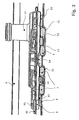
- Fig. 2 shows the attached to the oil pan 2 filter unit 1 in a sectional view.
- the filter unit 1 comprises a filter housing 11, which is formed from an upper housing part and a lower housing part, which are joined to one another at a flange 12.
- a filter medium for filtering oil in particular engine and / or transmission oil
- the located in the oil pan 2 and to be filtered oil underflows for this purpose the filter housing 11 and passes through the oil inlet opening 14 in the lower housing part into the interior of the filter unit 1, where it flows through the filter medium and thereby cleaned.
- a nozzle 13 is arranged, at the upper end of which there is an oil outlet opening for the filtered oil.
- the filter housing 11 is fixed by means of the two magnetic holder 3 on the inner surface of the oil pan 2.
- the attachment or holder is based on magnetic holding forces that emanate from the magnetic holders 3, but this is not absolutely necessary, as explained in more detail below (in connection with the Fig. 3 ).
- both the lower housing part of the filter housing 11 and the oil pan 2 are made of a magnetic material, in particular of a ferrous material.
- the upper end surfaces of the magnet holder 3 are in direct contact with the filter housing 11 and the housing lower part and the lower end surfaces are in direct contact with the inner surface of the oil pan 2. At the contact surfaces each magnetic retention is brought about.
- the positional positioning of the filter unit 1 relative to the oil sump 2 likewise takes place via the magnet holders 3.
- the magnet holders 3 are arranged in depressions 22 pointing away from the filter unit 1 in the oil sump 2, which position the magnet holders laterally or radially by positive locking.
- Such depressions and / or elevations may be referred to as fixing contours.
- these are integrally formed with the filter housing 11 and / or the oil pan 2.
- a spacing of the lower side of the filter housing 1 from the inner surface of the oil sump 2 takes place via the magnet holders 3.
- a typical spacing value is e.g. 2 to 5 mm. This spacing serves to form a gap which allows the underflow of the filter housing 11 with the oil to be filtered.
- the magnet holders 3 filtering out magnetic solid particles from the oil and binding them to themselves. This is a further function of the magnet holder 3. It is therefore preferred that the magnet holders 3 are arranged in the region of the oil inlet opening 14 of the filter housing 11 in such a way that the oil flowing into the oil inlet opening 14 enters the magnetic influence zone of the magnet holder 3.
- the spacing of the filter housing 11 to the inner surface of the oil pan 2 is further brought about by a plurality of molded in the oil pan 2 dome 23.
- the magnet holder 3 thus u.a. fulfill a spacing function and / or support function, advantageously, the number of domes 23 compared to the known from the prior art solutions can be reduced, or it may possibly be completely dispensed with such domes 23, whereby the manufacturing tools can be made simpler and a larger flow cross-section for underflow of the filter housing 11 is available.
- Fig. 3 shows an alternative attachment possibility of the filter unit 1 to the oil pan 2 by means of at least one magnetic holder 3a.
- the attachment or holder is based on positive locking elements in the form of resilient latching hooks 17 and 25 which are arranged on the underside of the filter unit 1 and the lower housing part and the oil pan 2 and the form-fitting the inner peripheral edge and the outer peripheral edge of Vietnamese Embrace magnet holder 3a, as shown.
- the oil pan 2 or the filter housing 11 may be formed of a non-magnetic material such as a plastic material or aluminum.
- spacer elements 41 and 42 are provided, which may be formed as separate elements or integrally formed with the filter housing 11, the oil pan 2 and / or the magnet holder 3a.
- the form-locking elements 17 and 25 can also be formed on the magnet holder 3a or arranged on the latter.
Landscapes
- Engineering & Computer Science (AREA)
- Mechanical Engineering (AREA)
- General Engineering & Computer Science (AREA)
- Lubrication Details And Ventilation Of Internal Combustion Engines (AREA)
- General Details Of Gearings (AREA)
Abstract
Description
Die Erfindung betrifft eine Ölwanne mit einer daran befestigten Ölfiltereinheit gemäß dem Oberbegriff des Anspruchs 1.The invention relates to an oil pan with an attached oil filter unit according to the preamble of
Bei der betreffenden Ölwanne handelt es sich vorzugsweise um eine Ölwanne für Motoren und/oder Getriebe für Kraftfahrzeuge, Baufahrzeuge und dergleichen. Aus dem Stand der Technik ist es bekannt, an der Innenfläche einer Ölwanne eine Filtereinheit anzuordnen, die der Filtration des Motor- und/oder Getriebeöls dient und die mit der Ölwanne quasi ein System bildet. Die Befestigung der Ölfiltereinheit an der Ölwanne erfolgt z.B. mittels einer Befestigungsvorrichtung, wie diese in der
Die Aufgabe der Erfindung ist es, die Befestigung einer Ölfiltereinheit an einer Ölwanne zu optimieren.The object of the invention is to optimize the attachment of an oil filter unit to an oil pan.
Diese Aufgabe wird gelöst durch eine Ölwanne mit einer Ölfiltereinheit gemäß dem Anspruch 1. Vorteilhafte und bevorzugte Weiterbildungen sind Gegenstand der abhängigen Ansprüche.This object is achieved by an oil pan with an oil filter unit according to
Erfindungsgemäß wird eine Ölwanne für Motoren und/oder Getriebe vorgeschlagen, mit einer, d.h. wenigstens einer, an der Innenfläche angeordneten Filtereinheit zur Filtration von Motoren- und/oder Getriebeöl, wobei die Filtereinheit mittels wenigstens eines Magnethalters an der Ölwanne befestigt ist.According to the invention, an oil sump for engines and / or transmissions is proposed, with one, i. at least one, arranged on the inner surface of the filter unit for filtering motor and / or gear oil, wherein the filter unit is attached by means of at least one magnetic holder to the oil pan.
Eine Ölwanne dient der unteren Abdeckung eines Motors und/oder Getriebes. Die Ölwanne dient auch als Reservoir für das zur Schmierung und/oder Kühlung von Motor und/oder Getriebe benötigte Schmiermittel. Ein solches Schmiermittel ist insbesondere ein Motoröl und/oder ein Getriebeöl. Bevorzugt handelt es sich bei der Ölwanne um ein separates Bauteil, welches abnehmbar am Motor und/oder Getriebe gehaltert ist. Die Anordnung einer Filtereinheit im Inneren der Ölwanne bietet diverse Vorteile, wie z.B. eine hervorragende Bauraumausnutzung.An oil pan serves the lower cover of an engine and / or transmission. The sump also serves as a reservoir for the lubricant needed to lubricate and / or cool the engine and / or transmission. Such a lubricant is in particular an engine oil and / or a transmission oil. Preferably, the oil pan is a separate component, which is detachably mounted on the engine and / or gearbox. The arrangement of a filter unit inside the sump offers various advantages, such as an excellent space utilization.
Die an der Ölwanne befestigte Filtereinheit umfasst ein einteiliges oder mehrteiliges Filtergehäuse, in dem wenigsten ein Filtermedium angeordnet ist. Das Filtergehäuse weist wenigstens eine Öleinlassöffnung und wenigstens eine Ölauslassöffnung auf. Bei der Filtereinheit kann es sich um eine Saugölfiltervorrichtung handeln, bei welcher das zu filtrierende Öl von einer Pumpe beaufschlagt durch das Filtermedium gesaugt wird. Bei der Filtereinheit kann es sich aber auch um eine Druckölfiltervorrichtung handeln, bei der das zu filtrierende Öl von einer Pumpe beaufschlagt durch das Filtermedium gedrückt wird. Die erfindungsgemäße Befestigung der Filtereinheit an der Ölwanne erfolgt bevorzugt zwischen einem Abschnitt des Filtergehäuses und einem Abschnitt der Innenfläche bzw. Innenseite der Ölwanne, insbesondere derart, dass eine Unterseite des Filtergehäuses der Innenfläche der Ölwanne zumindest abschnittsweise zugewandt ist. Auch können sich die Unterseite des Filtergehäuses und die Innenfläche der Ölwanne punktuell berühren. Die Filtereinheit kann permanent oder auch auswechselbar an bzw. in der Ölwanne befestigt sein. Die erfindungsgemäße Befestigung mittels wenigstens eines Magnethalters soll jedoch dauerhafter Art sein, womit gemeint ist, dass auch über eine lange Betriebsdauer stets eine funktionssichere Befestigung gewährleistet ist.The attached to the oil pan filter unit comprises a one-piece or multi-part filter housing in which at least one filter medium is arranged. The filter housing has at least one oil inlet opening and at least one oil outlet opening. The filter unit may be a suction oil filter device in which the oil to be filtered is sucked by a pump through the filter medium. However, the filter unit may also be a pressure oil filter device in which the oil to be filtered is pressed by a pump through the filter medium. The attachment of the filter unit according to the invention to the oil sump is preferably effected between a section of the filter housing and a section of the inner surface or inside of the sump, in particular such that an underside of the filter housing faces the inner surface of the sump at least in sections. Also, the underside of the filter housing and the inner surface of the oil pan can touch selectively. The filter unit can be permanently or exchangeably attached to or in the oil sump. However, the attachment according to the invention by means of at least one magnetic holder should be permanent in nature, by which it is meant that a functionally reliable attachment is always ensured even over a long period of operation.
Im Sinne der Erfindung ist ein Magnethalter bzw. ein magnetischer Halter ein einteiliges oder mehrteiliges Bauteil, welches eine Befestigungsfunktion erfüllt. Wesentlich ist, dass dieses Bauteil permanentmagnetische Eigenschaften aufweist. Die Befestigungsfunktion kann unabhängig von diesen permanentmagnetischen Eigenschaften sein. Bevorzugt ist der Magnethalter zumindest teilweise aus einem permanentmagnetischen Material gebildet. Der Magnethalter kann vollständig aus einem solchen permanentmagnetischen Material gebildet sein. Ein solches permanentmagnetisches Material kann in einem Gehäuse eingebettet sein.For the purposes of the invention, a magnetic holder or a magnetic holder is a one-part or multi-part component, which fulfills a fastening function. It is essential that this component has permanent magnetic properties. The attachment function may be independent of these permanent magnetic properties. Preferably, the magnet holder is at least partially formed from a permanent magnetic material. The magnet holder may be formed entirely from such a permanent magnetic material. Such a permanent magnetic material may be embedded in a housing.
Eine Idee der Erfindung ist es, mit dem Magnethalter eine Befestigungseinrichtung bereitzustellen, die mehrere Funktionen wahrnehmen kann, wie diese insbesondere nachfolgend im Zusammenhang mit den Figuren im Einzelnen erläutert werden. So ist gemäß einer bevorzugten Weiterbildung vorgesehen, dass der Magnethalter gleichfalls zum Herausfiltern von metallischen Verunreinigungen (Urschmutz oder während des Betriebs auftretende Verschmutzungen aus einem magnetischen Metallmaterial) aus dem zu filtrierenden Motor- und/oder Getriebeöl dient. Hierbei werden die metallischen Verunreinigungen durch magnetische Kraft dauerhaft an den Magnethalter gebunden. Es kann von Vorteil sein, wenn der Magnethalter im Bereich einer Öleinlassöffnung des Filtergehäuses der Filtereinheit angeordnet ist, da dann das zu filtrierende Öl quasi am Magnethalter vorbeiströmen muss. Die Filterfunktion des Magnethalters ist jedoch unabhängig von der Befestigungsfunktion. In vorteilhafter Weise können die aus dem Stand der Technik bekannten Magnete zur Bindung metallischer Verunreinigungen für die erfindungsgemäße Lösung, d.h. für das Befestigen der Filtereinheit an der Ölwanne, herangezogen werden, was eine Bauteil- und Funktionsoptimierung, sowie Kostenoptimierung darstellt.One idea of the invention is to provide with the magnetic holder a fastening device which can perform a plurality of functions, as these are explained in detail below in particular in connection with the figures. Thus, according to a preferred embodiment, the magnet holder is likewise used for filtering out metallic contaminants (original dirt or contaminants from a magnetic metal material occurring during operation) from the engine and / or transmission oil to be filtered. Here, the metallic impurities are permanently bound by magnetic force to the magnet holder. It may be advantageous if the magnet holder in the region of an oil inlet opening of the filter housing of the filter unit is arranged, since then the oil to be filtered almost has to flow past the magnet holder. However, the filter function of the magnet holder is independent of the attachment function. Advantageously, the known from the prior art magnets for binding metallic contaminants for the inventive solution, ie for attaching the filter unit to the oil pan, are used, which is a component and function optimization, and cost optimization.
Gemäß einer bevorzugten Weiterbildung ist vorgesehen, dass ein Magnethalter eine magnetische Befestigung der Filtereinheit an der Ölwanne bewirkt. Die dem Magnethalter innewohnenden magnetischen Kräfte können in diesem Fall eine Doppelfunktion erfüllen, nämlich die Befestigung des Ölfiltereinheit an der Ölwanne und die Bindung metallischer Verunreinigungen im zu filtrierenden Motor- und/oder Getriebeöl, wie zuvor beschrieben. Die magnetische Befestigung gelingt besonders gut, wenn die Ölwanne und/oder das Filtergehäuse der Filtereinheit zumindest im Bereich der Befestigung mittels des Magnethalters aus einem magnetischen Material gebildet ist/sind. Alternativ kann der betreffende Bereich z.B. auch mit einem solchen magnetischen Material unterlegt werden.According to a preferred embodiment, it is provided that a magnet holder causes a magnetic attachment of the filter unit to the oil pan. The magnetic forces inherent in the magnet holder can in this case fulfill a dual function, namely the attachment of the oil filter unit to the oil sump and the binding of metallic contaminants in the engine and / or transmission oil to be filtered, as described above. The magnetic attachment succeeds particularly well when the oil pan and / or the filter housing of the filter unit is / are formed at least in the region of the attachment by means of the magnetic holder made of a magnetic material. Alternatively, the area in question may be e.g. be backed with such a magnetic material.
Alternativ und/oder ergänzend zur magnetischen Befestigung der Filtereinheit an der Ölwanne ist gemäß einer bevorzugten Weiterbildung vorgesehen, dass ein Magnethalter eine formschlüssige Befestigung der Filtereinheit an der Ölwanne bewirkt. Diese formschlüssige Befestigung gelingt besonders gut mittels von Formschlusselementen und insbesondere Rastelementen, die an dem Magnethalter ausgebildet sind und/oder die an der Ölwanne und/oder der Filtereinheit bzw. deren Filtergehäuse ausgebildet sind und die am Magnethalter angreifen. Solche Rastelemente können z.B. Rasthaken sein, die in korrespondierende Rastelemente oder Rastabschnitte eingreifen. Eine formschlüssige Befestigung mittels des Magnethalters ermöglicht, dass die Ölwanne und/oder das Filtergehäuse der Filtereinheit zumindest im Bereich der Befestigung mittels des Magnethalters aus einem nicht-magnetischen Material gebildet sein kann. Insbesondere kann das Filtergehäuse und/oder die Ölwanne zumindest bereichsweise aus einem Kunststoffmaterial oder Aluminiummaterial (oder dergleichen) gebildet sein. Prinzipiell sind unterschiedlichste Materialpaarungen von Filtergehäuse und Ölwanne möglich. Eine formschlüssige Befestigung ist jedoch auch bei Verwendung metallischer Materialien möglich und kann in diesem Fall die Befestigungsfunktion des Magnethalters vorteilhaft unterstützen.Alternatively and / or in addition to the magnetic attachment of the filter unit to the oil pan is provided according to a preferred development that a magnetic holder causes a positive attachment of the filter unit to the oil pan. This positive fastening succeeds particularly well by means of positive locking elements and in particular locking elements which are formed on the magnet holder and / or which are formed on the oil pan and / or the filter unit or its filter housing and which engage the magnet holder. Such locking elements may e.g. Be latching hooks which engage in corresponding locking elements or latching sections. A positive fastening by means of the magnet holder makes it possible for the oil sump and / or the filter housing of the filter unit to be formed from a non-magnetic material at least in the region of the fastening by means of the magnet holder. In particular, the filter housing and / or the oil pan can be formed at least in regions from a plastic material or aluminum material (or the like). In principle, a wide variety of material combinations of filter housing and oil sump are possible. However, a positive attachment is possible even when using metallic materials and can advantageously support the attachment function of the magnet holder in this case.
Gemäß einer bevorzugten Weiterbildung ist vorgesehen, dass die Lagepositionierung der Filtereinheit relativ zur Ölwanne durch Vertiefungen erfolgt, welche in die Ölwanne und/oder in das Filtergehäuse der Filtereinheit eingebracht sind und in die ein Magnethalter formschlüssig einsitzt. Ebenso ist es möglich, in der Ölwanne und/oder dem Filtergehäuse Erhöhungen auszubilden, auf welche ein Magnethalter formschlüssig aufgesteckt wird. Solche Erhöhungen können als Dome bezeichnet werden. Eine Vertiefung weist vom korrespondierenden Bauteil (Filtereinheit oder Ölwanne) weg, eine Erhöhung weist auf das korrespondierende Bauteil zu.According to a preferred embodiment, it is provided that the position positioning of the filter unit takes place relative to the oil pan by depressions, which are introduced into the oil pan and / or in the filter housing of the filter unit and in which a magnetic holder form-fitting seated. It is also possible to form elevations in the oil sump and / or the filter housing, onto which a magnetic holder is plugged in a form-fitting manner. Such elevations may be referred to as domes. A depression points away from the corresponding component (filter unit or oil sump), an increase points to the corresponding component.
Gemäß einer bevorzugten Weiterbildung ist vorgesehen, dass der Magnethalter an der Unterseite des Filtergehäuses und/oder an der Innenfläche der Ölwanne festgeklebt ist. Eine solche Verklebung führt eine dauerhafte Verbindung zwischen Magnethalter und Filtergehäuse und/oder Ölwanne herbei und erleichtert z.B. die Montage. Insbesondere kann der Magnethalter in einer Vertiefung oder auf einer Erhöhung (wie zuvor erläutert) festgeklebt sein. Eine solche Verklebung kann auch mit Formschlusselementen (wie oben erläutert) kombiniert werden. Anstelle einer Verklebung kann auch eine Verlötung, Verschweißung, Vernietung oder dergleichen vorgesehen sein. Eine Verklebung ist prinzipiell bei allen Materialien möglich, eignet sich insbesondere jedoch bei nichtmetallischen und nicht magnetischen Materialien, wie z.B. bei einer Kunststoff-Ölwanne oder einem Kunststoff-Filtergehäuse.According to a preferred embodiment, it is provided that the magnet holder is glued to the underside of the filter housing and / or on the inner surface of the oil pan. Such bonding leads to a permanent connection between magnet holder and filter housing and / or oil pan and facilitates e.g. the assembly. In particular, the magnet holder can be glued in a recess or on a raised portion (as explained above). Such a bond can also be combined with positive-locking elements (as explained above). Instead of a bond, a soldering, welding, riveting or the like may be provided. Bonding is possible in principle with all materials, but is particularly suitable for non-metallic and non-magnetic materials, such as e.g. in a plastic oil pan or a plastic filter housing.
Gemäß einer bevorzugten weiterbildung ist vorgesehen, dass der Magnethalter als Abstandshalter zwischen der Unterseite der Filtereinheit bzw. deren Filtergehäuse und der Innenfläche der Ölwanne dient. Hierdurch lässt sich mit geringem Aufwand ein Beabstandung der Unterseite des Filtergehäuses und der Innenfläche der Ölwanne herstellen, wodurch eine Unterströmung des Filtergehäuses ermöglicht wird. Hierdurch ist eine anzustrebende Positionierung der Öleinlassöffnung auf der Unterseite des Filtergehäuses möglich.According to a preferred embodiment, it is provided that the magnet holder serves as a spacer between the underside of the filter unit or its filter housing and the inner surface of the oil pan. This makes it possible to produce a spacing of the underside of the filter housing and the inner surface of the oil pan with little effort, whereby an underflow of the filter housing is made possible. As a result, an aspired positioning of the oil inlet opening on the underside of the filter housing is possible.
Gemäß einer bevorzugten Weiterbildung ist vorgesehen, dass der Magnethalter kreisringzylindrisch ausgebildet ist. D.h. der Magnethalter, weist eine obere kreisringförmige Stirnfläche und einer untere kreisringförmige Stirnfläche, sowie eine axiale Erstreckung zwischen diesen Stirnflächen auf. Die kreisringzylindrische Ausbildung führt zu großen Stirnflächen, die als Auflageflächen und/oder Stützflächen genutzt werden können, bei einem verhältnismäßig geringem Gewicht des Magnethalters. Ein weiterer Vorteil ist die Möglichkeit zur formschlüssigen Befestigung auf einem Dom, wie nachfolgend noch näher erläutert.According to a preferred embodiment, it is provided that the magnet holder is formed annular cylindrical. That the magnet holder, has an upper annular end face and a lower annular end face, and an axial extension between these end faces. The annular cylindrical design leads to large end faces, which can be used as bearing surfaces and / or support surfaces, with a relatively low weight of the magnet holder. Another advantage is the possibility for positive attachment to a dome, as explained in more detail below.
Die Erfindung wird nachfolgend beispielhaft anhand der Figuren näher erläutert. Es zeigen:
- Fig. 1:
- die erfindungsgemäße Befestigung einer Filtereinheit an der Innenfläche einer Öl- wanne in einer Explosionsdarstellung;
- Fig. 2:
- die nach
Fig. 1 an der Innenfläche der Ölwanne befestigte Filtereinheit in einer Schnittansicht; und - Fig. 3:
- eine alternative Ausführung der Befestigung nach
Fig. 2 in einer schematischen De- tail-Schnittansicht.
- Fig. 1:
- the attachment according to the invention of a filter unit on the inner surface of an oil pan in an exploded view;
- Fig. 2:
- the after
Fig. 1 attached to the inner surface of the oil pan filter unit in a sectional view; and - 3:
- an alternative embodiment of the attachment to
Fig. 2 in a schematic detail sectional view.
Das Filtergehäuse 11 ist mittels der beiden Magnethalter 3 an der Innenfläche der Ölwanne 2 befestigt. Die Befestigung bzw. Halterung beruht auf magnetischen Haltekräften, die von den Magnethaltern 3 ausgehen, was jedoch nicht zwingend erforderlich ist, wie nachfolgend noch näher erläutert (im Zusammenhang mit der
. Die Lagepositionierung der Filtereinheit 1 relativ zur Ölwanne 2 erfolgt gleichfalls über die Magnethalter 3. Hierzu sind die Magnethalter 3 in von der Filtereinheit 1 wegweisenden Vertiefungen 22 in der Ölwanne 2 angeordnet, welche die Magnethalter seitlich bzw. radial durch Formschluss positionieren. Am Gehäuseunterteil der Ölwanne 2 sind nach unten, d.h. in Richtung der Ölwanne 2, weisende Erhöhungen bzw. Dome 15 ausgebildet, welche formschlüssig und zentrierend in die axiale Mittelbohrung 31 der kreisringzylindrischen Magnethalter 3 eingreifen (formschlüssige Befestigung auf einem Dom, wie bereits oben erwähnt). Ebenso ist es auch möglich, Vertiefungen am Filtergehäuse 11 und Erhöhungen bzw. Dome an der Ölwanne 2 vorzusehen. Solche Vertiefungen und/oder Erhöhungen können als Fixierkonturen bezeichnet werden. Bevorzugt sind diese integral mit dem Filtergehäuse 11 und/oder der Ölwanne 2 ausgebildet., The positional positioning of the
Über die Magnethalter 3 erfolgt ferner eine Beabstandung der Unterseite des Filtergehäuses 1 zur Innenfläche der Ölwanne 2. Ein typischer Beabstandungswert ist z.B. 2 bis 5 mm. Diese Beabstandung dient zur Bildung eines Spalts, der die Unterströmung des Filtergehäuses 11 mit dem zu filtrierenden Öl ermöglicht. Beim Unterströmen ist es vorteilhaft, dass das in die Öleinlassöffnung 14 einströmende Öl an den Magnethaltern 3 vorbeifließt oder diese umströmt, wobei die Magnethalter 3 magnetische Festpartikel aus dem Öl herausfiltern und an sich binden. Dies ist eine weitere Funktion der Magnethalter 3. Bevorzugt ist daher, dass die Magnethalter 3 im Bereich der Öleinlassöffnung 14 des Filtergehäuses 11 angeordnet werden und zwar derart, dass das in die Öleinlassöffnung 14 einströmende Öl in die magnetische Einflusszone der Magnethalter 3 gelangt. Die Beabstandung des Filtergehäuses 11 zur Innenfläche der Ölwanne 2 wird ferner durch mehrere in der Ölwanne 2 eingeformte Dome 23 herbeigeführt. Im Ergebnis wir damit eine Mehrpunktauflage für die Filtereinheit 1 erreicht, bei der das Filtergehäuse 11 unmittelbar und mittelbar, d.h. mittels der Magnethalter 3, an der Ölwanne anliegt. Da die Magnethalter 3 damit u.a. eine Beabstandungsfunktion und/oder Stützfunktion erfüllen, kann in vorteilhafter Weise die Anzahl der Dome 23 gegenüber den aus dem Stand der Technik bekannten Lösungen reduziert werden, oder es kann ggf. auch vollständig auf solche Dome 23 verzichtet werden, wodurch die Herstellungswerkzeuge einfacher gestaltet werden können und ein größerer Fließquerschnitt zur Unterströmung des Filtergehäuses 11 bereitsteht.Furthermore, a spacing of the lower side of the
Claims (12)
dadurch gekennzeichnet,
dass die Filtereinheit (1) mittels wenigstens eines Magnethalters (3, 3a) an der Ölwanne (2) befestigt ist.Oil sump (2) for engines and / or transmissions with a filter unit (1) arranged on the inner surface for the filtration of engine and / or transmission oil,
characterized,
in that the filter unit (1) is fastened to the oil sump (2) by means of at least one magnet holder (3, 3a).
dadurch gekennzeichnet,
dass der Magnethalter (3, 3a) gleichfalls zum Herausfiltern von metallischen Verunreinigungen aus dem zu filtrierenden Motor- und/oder Getriebeöl dient.Oil sump (2) according to claim 1,
characterized,
that the magnet holder (3, 3a) also serves to filter out metallic contaminants from the engine and / or transmission oil to be filtered.
dadurch gekennzeichnet,
dass der Magnethalter (3, 3a) im Bereich einer Öleinlassöffrung (14) des Filtergehäuses (11) der Filtereinheit (1) angeordnet ist.Oil sump (2) according to claim 2
characterized,
in that the magnet holder (3, 3a) is arranged in the region of an oil inlet opening (14) of the filter housing (11) of the filter unit (1).
dadurch gekennzeichnet,
dass der Magnethalter (3, 3a) eine magnetische Befestigung der Filtereinheit (1) an der Ölwanne (2) bewirkt.Oil sump (2) according to one of the preceding claims,
characterized,
that the magnet holder (3, 3a) causes a magnetic attachment of the filter unit (1) on the oil sump (2).
dadurch gekennzeichnet,
dass die Ölwanne (2) und/oder das Filtergehäuse (11) der Filtereinheit (1) zumindest im Bereich der Befestigung mittels des Magnethalters (3, 3a) aus einem magnetischen Material gebildet ist/sind.Oil sump (2) according to claim 4,
characterized,
that the oil pan (2) and / or the filter housing (11) of the filter unit (1) at least in the region of the fastening means of the magnet holder (3, 3a) is formed of a magnetic material / are.
dadurch gekennzeichnet,
dass der Magnethalter (3, 3a) eine formschlüssige Befestigung der Filtereinheit (1) an der Ölwanne (2) bewirkt.Oil sump (2) according to one of the preceding claims,
characterized,
that the magnet holder (3, 3a) causes a positive-locking fixing of the filter unit (1) on the oil sump (2).
dadurch gekennzeichnet,
dass die formschlüssige Befestigung mittels von Rastelementen (17; 25) erfolgt, die an dem Magnethalter (3, 3a) ausgebildet sind und/oder die am Magnethalter (3, 3a) angreifen.Oil sump (2) according to claim 6,
characterized,
in that the positive fastening is effected by means of latching elements (17; 25) which are formed on the magnet holder (3, 3a) and / or which act on the magnet holder (3, 3a).
dadurch gekennzeichnet,
dass die Ölwanne (2) und/oder das Filtergehäuse (11) der Filtereinheit (1) zumindest im Bereich der Befestigung mittels des Magnethalters (3, 3a) aus einem nicht-magnetischen Material, insbesondere aus einem Kunststoffmaterial oder Aluminiummaterial, gebildet ist/sind.Oil sump (2) according to claim 6 or 7,
characterized,
that the oil pan (2) and / or the filter housing (11) of the filter unit (1) in the region of the fastening means of the magnet holder (3, 3a) is formed of a non-magnetic material, in particular of a plastic material or aluminum material is / are at least ,
dadurch gekennzeichnet,
dass die Lagepositionierung der Filtereinheit (1) relativ zur Ölwanne (2) durch Vertiefungen (22) erfolgt, welche in die Ölwanne (2) und/oder in das Filtergehäuse (11) der Filtereinheit (1) eingebracht sind und in die der Magriethalter (3, 3a) formschlüssig einsitzt.Oil sump, (2) according to one of the preceding claims,
characterized,
in that the positional positioning of the filter unit (1) relative to the oil sump (2) is effected by depressions (22) which are introduced into the sump (2) and / or into the filter housing (11) of the filter unit (1) and into which the magret holder ( 3, 3a) is positively seated.
dadurch gekennzeichnet,
dass der Magnethalter (3, 3a) an der Unterseite des Filtergehäuses (11) der Filtereinheit (1) und/oder der Innenfläche der Innenfläche der Ölwanne (2) festgeklebt ist.Oil sump (2) according to one of the preceding claims,
characterized,
in that the magnet holder (3, 3a) is glued to the underside of the filter housing (11) of the filter unit (1) and / or the inner surface of the inner surface of the oil sump (2).
dadurch gekennzeichnet,
dass der Magnethalter (3, 3a) als Abstandshalter zwischen der Unterseite der Filtereinheit (1) und der Innenfläche der Ölwanne (2) dient.Oil sump (2) according to one of the preceding claims,
characterized,
in that the magnet holder (3, 3a) serves as a spacer between the underside of the filter unit (1) and the inner surface of the oil sump (2).
dadurch gekennzeichnet,
dass der Magnethalter (3, 3a) kreisringzylindrisch ausgebildet ist.Oil sump (2) according to one of the preceding claims,
characterized,
that the magnet holder (3, 3a) is formed annular cylindrical.
Priority Applications (1)
| Application Number | Priority Date | Filing Date | Title |
|---|---|---|---|
| EP12001747.0A EP2489841B1 (en) | 2009-08-10 | 2010-06-11 | Oil tray with an attached oil filter unit |
Applications Claiming Priority (1)
| Application Number | Priority Date | Filing Date | Title |
|---|---|---|---|
| DE102009036852.3A DE102009036852B4 (en) | 2009-08-10 | 2009-08-10 | Oil pan with an attached oil filter unit |
Related Child Applications (1)
| Application Number | Title | Priority Date | Filing Date |
|---|---|---|---|
| EP12001747.0A Division EP2489841B1 (en) | 2009-08-10 | 2010-06-11 | Oil tray with an attached oil filter unit |
Publications (2)
| Publication Number | Publication Date |
|---|---|
| EP2284367A2 true EP2284367A2 (en) | 2011-02-16 |
| EP2284367A3 EP2284367A3 (en) | 2011-09-14 |
Family
ID=43048877
Family Applications (2)
| Application Number | Title | Priority Date | Filing Date |
|---|---|---|---|
| EP10006042A Withdrawn EP2284367A3 (en) | 2009-08-10 | 2010-06-11 | Oil tray with an attached oil filter unit |
| EP12001747.0A Not-in-force EP2489841B1 (en) | 2009-08-10 | 2010-06-11 | Oil tray with an attached oil filter unit |
Family Applications After (1)
| Application Number | Title | Priority Date | Filing Date |
|---|---|---|---|
| EP12001747.0A Not-in-force EP2489841B1 (en) | 2009-08-10 | 2010-06-11 | Oil tray with an attached oil filter unit |
Country Status (2)
| Country | Link |
|---|---|
| EP (2) | EP2284367A3 (en) |
| DE (1) | DE102009036852B4 (en) |
Cited By (5)
| Publication number | Priority date | Publication date | Assignee | Title |
|---|---|---|---|---|
| EP2578289A1 (en) * | 2011-10-05 | 2013-04-10 | Honda Motor Co., Ltd. | Oil filter |
| CN103573329A (en) * | 2013-11-19 | 2014-02-12 | 浙江吉利汽车研究院有限公司 | Automobile magnetic oil pan |
| US9291306B2 (en) | 2014-05-08 | 2016-03-22 | Patrick Conlan | Oil filter changing system |
| WO2018130269A1 (en) * | 2017-01-10 | 2018-07-19 | Purodur Gmbh | Filter cartridge for a liquid tank of a domestic appliance |
| CN113250784A (en) * | 2021-06-18 | 2021-08-13 | 中国北方发动机研究所(天津) | Oil pan structure |
Families Citing this family (4)
| Publication number | Priority date | Publication date | Assignee | Title |
|---|---|---|---|---|
| DE102017209987B4 (en) * | 2017-06-13 | 2024-10-10 | Zf Friedrichshafen Ag | Oil pan of a transmission of a motor vehicle with an oil filter and an oil pan gasket |
| DE102017210556A1 (en) | 2017-06-22 | 2018-12-27 | Zf Friedrichshafen Ag | Unit consisting of an oil pan and an oil filter of a transmission of a motor vehicle |
| DE102021114927A1 (en) | 2021-06-10 | 2022-12-15 | Schaeffler Technologies AG & Co. KG | Oil housing pan with oil filter element |
| DE102024128316A1 (en) * | 2024-09-30 | 2026-04-02 | Voith Patent Gmbh | Oil pan for a drive unit |
Citations (4)
| Publication number | Priority date | Publication date | Assignee | Title |
|---|---|---|---|---|
| JPH0281996U (en) * | 1988-12-13 | 1990-06-25 | ||
| DE102006005551A1 (en) * | 2005-02-07 | 2006-08-10 | Spx Corporation | Integrated wafer device with waffle pattern and method |
| DE102005025726A1 (en) | 2005-06-04 | 2006-12-07 | Ibs Filtran Kunststoff-/ Metallerzeugnisse Gmbh | Fastening device and method for fixing a component in an oil sump |
| DE102008038958A1 (en) | 2008-08-13 | 2010-02-18 | Ibs Filtran Kunststoff-/ Metallerzeugnisse Gmbh | Oil pan with oil filter to carrier unit |
Family Cites Families (4)
| Publication number | Priority date | Publication date | Assignee | Title |
|---|---|---|---|---|
| US4995971A (en) * | 1989-08-07 | 1991-02-26 | Ford Motor Company | Dual purpose automatic transmission oil pan |
| DE19735444C2 (en) * | 1997-06-17 | 1999-04-15 | Ibs Filtran Kunststoff Metall | Oil filter insert for oil sumps of engines and transmissions |
| JP4263375B2 (en) | 2001-02-09 | 2009-05-13 | 矢崎総業株式会社 | Display source unit for vehicle display device |
| US6840042B1 (en) * | 2003-06-17 | 2005-01-11 | Hydro-Gear Limited Partnership | Internal filter |
-
2009
- 2009-08-10 DE DE102009036852.3A patent/DE102009036852B4/en active Active
-
2010
- 2010-06-11 EP EP10006042A patent/EP2284367A3/en not_active Withdrawn
- 2010-06-11 EP EP12001747.0A patent/EP2489841B1/en not_active Not-in-force
Patent Citations (4)
| Publication number | Priority date | Publication date | Assignee | Title |
|---|---|---|---|---|
| JPH0281996U (en) * | 1988-12-13 | 1990-06-25 | ||
| DE102006005551A1 (en) * | 2005-02-07 | 2006-08-10 | Spx Corporation | Integrated wafer device with waffle pattern and method |
| DE102005025726A1 (en) | 2005-06-04 | 2006-12-07 | Ibs Filtran Kunststoff-/ Metallerzeugnisse Gmbh | Fastening device and method for fixing a component in an oil sump |
| DE102008038958A1 (en) | 2008-08-13 | 2010-02-18 | Ibs Filtran Kunststoff-/ Metallerzeugnisse Gmbh | Oil pan with oil filter to carrier unit |
Cited By (8)
| Publication number | Priority date | Publication date | Assignee | Title |
|---|---|---|---|---|
| EP2578289A1 (en) * | 2011-10-05 | 2013-04-10 | Honda Motor Co., Ltd. | Oil filter |
| CN103028283A (en) * | 2011-10-05 | 2013-04-10 | 本田技研工业株式会社 | Oil filter |
| CN103028283B (en) * | 2011-10-05 | 2015-08-26 | 本田技研工业株式会社 | oil filter |
| CN103573329A (en) * | 2013-11-19 | 2014-02-12 | 浙江吉利汽车研究院有限公司 | Automobile magnetic oil pan |
| CN103573329B (en) * | 2013-11-19 | 2017-01-11 | 浙江吉利汽车研究院有限公司 | Automobile magnetic oil pan |
| US9291306B2 (en) | 2014-05-08 | 2016-03-22 | Patrick Conlan | Oil filter changing system |
| WO2018130269A1 (en) * | 2017-01-10 | 2018-07-19 | Purodur Gmbh | Filter cartridge for a liquid tank of a domestic appliance |
| CN113250784A (en) * | 2021-06-18 | 2021-08-13 | 中国北方发动机研究所(天津) | Oil pan structure |
Also Published As
| Publication number | Publication date |
|---|---|
| DE102009036852A1 (en) | 2011-02-24 |
| DE102009036852B4 (en) | 2015-04-16 |
| EP2489841B1 (en) | 2017-03-22 |
| EP2489841A1 (en) | 2012-08-22 |
| EP2284367A3 (en) | 2011-09-14 |
Similar Documents
| Publication | Publication Date | Title |
|---|---|---|
| EP2489841B1 (en) | Oil tray with an attached oil filter unit | |
| EP1339954B1 (en) | Metal oil pan with an integrated oil filter | |
| EP3096861B1 (en) | Replaceable filter of a filter device, and filter device | |
| DE102011080493B3 (en) | Switching device of a motor vehicle transmission | |
| DE102008027662A1 (en) | Oil pan with oil filter | |
| EP0897317A1 (en) | End disc for an annular filter element with a seal which acts radially | |
| EP2190556A1 (en) | Filter appliance | |
| EP2154339A1 (en) | Oil sump with oil filter on carrier unit | |
| DE102011118313B4 (en) | DISC BRAKE, ESPECIALLY FOR COMMERCIAL VEHICLES, AS WELL AS BRAKE PAD AND PRESSURE PLATE AS SEPARATE COMPONENTS FOR SUCH A DISC BRAKE | |
| WO2015052305A2 (en) | Brake carrier for a sliding caliper disk brake and brake caliper for a disk brake | |
| DE102007051475A1 (en) | Connector for inner ring and e.g. Oldham disc, has snapping pin provided with detent element at its end and offset compensation element, and inner ring provided with bore holes for admission of snapping pin | |
| DE102008047190A1 (en) | Brake disk for motor vehicle, particularly passenger car or truck, has brake disk pot and friction ring, where brake disk pot and friction ring are sectionally connected with each other by adhesive joint | |
| DE602004005628T2 (en) | Bracket with several bridges | |
| EP2434183B1 (en) | Method for filtering lubricants in a transmission | |
| EP2683563A1 (en) | Spring bracket arm of a spring bracket of a motor vehicle axle | |
| DE202005014125U1 (en) | Filter useful for removing oil from gas streams consists exclusively of components that are nonmetallic but can withstand a high pressure difference between the outside and inside of the filter | |
| DE102012017319B4 (en) | Fastening arrangement between a radial bearing and a support arm | |
| WO2015011045A1 (en) | Master brake cylinder assembly of a motor vehicle brake system having a filter element, and fluid reservoir and insert element therefor | |
| EP1975490A2 (en) | Device for holding at least one extended component | |
| DE102005034862B3 (en) | With a flywheel provided component and method for manufacturing and mounting a flywheel | |
| DE102008000728A1 (en) | Hand tool, in particular hand-guided grinding machine | |
| EP1602862B1 (en) | Device for conveying shift movement in a gearbox for vehicle | |
| EP1059465B1 (en) | Device for mounting a caliper to a wheel carrier | |
| EP2824352A1 (en) | Brake lining mount of a disc brake for a commercial vehicle | |
| DE102012012940A1 (en) | Filter holding frame for filter system for filtering e.g. gaseous fluid in air filter of motor car, has secondary sub-frame that is provided with filter element while other primary sub-frame is fixedly connected to detent connection |
Legal Events
| Date | Code | Title | Description |
|---|---|---|---|
| PUAI | Public reference made under article 153(3) epc to a published international application that has entered the european phase |
Free format text: ORIGINAL CODE: 0009012 |
|
| AK | Designated contracting states |
Kind code of ref document: A2 Designated state(s): AL AT BE BG CH CY CZ DE DK EE ES FI FR GB GR HR HU IE IS IT LI LT LU LV MC MK MT NL NO PL PT RO SE SI SK SM TR |
|
| AX | Request for extension of the european patent |
Extension state: BA ME RS |
|
| PUAL | Search report despatched |
Free format text: ORIGINAL CODE: 0009013 |
|
| AK | Designated contracting states |
Kind code of ref document: A3 Designated state(s): AL AT BE BG CH CY CZ DE DK EE ES FI FR GB GR HR HU IE IS IT LI LT LU LV MC MK MT NL NO PL PT RO SE SI SK SM TR |
|
| AX | Request for extension of the european patent |
Extension state: BA ME RS |
|
| RIC1 | Information provided on ipc code assigned before grant |
Ipc: F01M 11/00 20060101AFI20110811BHEP |
|
| 17P | Request for examination filed |
Effective date: 20120314 |
|
| 17Q | First examination report despatched |
Effective date: 20140815 |
|
| STAA | Information on the status of an ep patent application or granted ep patent |
Free format text: STATUS: THE APPLICATION IS DEEMED TO BE WITHDRAWN |
|
| 18D | Application deemed to be withdrawn |
Effective date: 20180516 |