EP2284380A2 - Verfahren zur Steuerung eines Common-Rail-Direkteinspritzungssystems - Google Patents
Verfahren zur Steuerung eines Common-Rail-Direkteinspritzungssystems Download PDFInfo
- Publication number
- EP2284380A2 EP2284380A2 EP10172447A EP10172447A EP2284380A2 EP 2284380 A2 EP2284380 A2 EP 2284380A2 EP 10172447 A EP10172447 A EP 10172447A EP 10172447 A EP10172447 A EP 10172447A EP 2284380 A2 EP2284380 A2 EP 2284380A2
- Authority
- EP
- European Patent Office
- Prior art keywords
- pressure pump
- fuel
- common rail
- low pressure
- high pressure
- Prior art date
- Legal status (The legal status is an assumption and is not a legal conclusion. Google has not performed a legal analysis and makes no representation as to the accuracy of the status listed.)
- Granted
Links
Images
Classifications
-
- F—MECHANICAL ENGINEERING; LIGHTING; HEATING; WEAPONS; BLASTING
- F02—COMBUSTION ENGINES; HOT-GAS OR COMBUSTION-PRODUCT ENGINE PLANTS
- F02D—CONTROLLING COMBUSTION ENGINES
- F02D41/00—Electrical control of supply of combustible mixture or its constituents
- F02D41/30—Controlling fuel injection
- F02D41/38—Controlling fuel injection of the high pressure type
- F02D41/3809—Common rail control systems
- F02D41/3836—Controlling the fuel pressure
- F02D41/3845—Controlling the fuel pressure by controlling the flow into the common rail, e.g. the amount of fuel pumped
- F02D41/3854—Controlling the fuel pressure by controlling the flow into the common rail, e.g. the amount of fuel pumped with elements in the low pressure part, e.g. low pressure pump
-
- F—MECHANICAL ENGINEERING; LIGHTING; HEATING; WEAPONS; BLASTING
- F02—COMBUSTION ENGINES; HOT-GAS OR COMBUSTION-PRODUCT ENGINE PLANTS
- F02D—CONTROLLING COMBUSTION ENGINES
- F02D41/00—Electrical control of supply of combustible mixture or its constituents
- F02D41/02—Circuit arrangements for generating control signals
- F02D41/14—Introducing closed-loop corrections
- F02D41/1401—Introducing closed-loop corrections characterised by the control or regulation method
- F02D2041/141—Introducing closed-loop corrections characterised by the control or regulation method using a feed-forward control element
-
- F—MECHANICAL ENGINEERING; LIGHTING; HEATING; WEAPONS; BLASTING
- F02—COMBUSTION ENGINES; HOT-GAS OR COMBUSTION-PRODUCT ENGINE PLANTS
- F02D—CONTROLLING COMBUSTION ENGINES
- F02D41/00—Electrical control of supply of combustible mixture or its constituents
- F02D41/02—Circuit arrangements for generating control signals
- F02D41/14—Introducing closed-loop corrections
- F02D41/1401—Introducing closed-loop corrections characterised by the control or regulation method
- F02D2041/1413—Controller structures or design
- F02D2041/1418—Several control loops, either as alternatives or simultaneous
- F02D2041/1419—Several control loops, either as alternatives or simultaneous the control loops being cascaded, i.e. being placed in series or nested
-
- F—MECHANICAL ENGINEERING; LIGHTING; HEATING; WEAPONS; BLASTING
- F02—COMBUSTION ENGINES; HOT-GAS OR COMBUSTION-PRODUCT ENGINE PLANTS
- F02D—CONTROLLING COMBUSTION ENGINES
- F02D2200/00—Input parameters for engine control
- F02D2200/02—Input parameters for engine control the parameters being related to the engine
- F02D2200/06—Fuel or fuel supply system parameters
- F02D2200/0602—Fuel pressure
-
- F—MECHANICAL ENGINEERING; LIGHTING; HEATING; WEAPONS; BLASTING
- F02—COMBUSTION ENGINES; HOT-GAS OR COMBUSTION-PRODUCT ENGINE PLANTS
- F02D—CONTROLLING COMBUSTION ENGINES
- F02D2250/00—Engine control related to specific problems or objectives
- F02D2250/31—Control of the fuel pressure
Definitions
- the present invention relates to a method for controlling a direct injection system of the common-rail type.
- a high pressure pump receives a flow of fuel from a tank by means of a low pressure pump and feeds the fuel to a common rail, hydraulically connected to a plurality of injectors.
- the pressure of the fuel inside the common rail is to be constantly controlled according to the engine point either by varying the instantaneous delivery of the high pressure pump or by constantly feeding an excess of fuel to the common rail and discharging the excess fuel from the common rail itself by means of a regulating valve.
- the solution of regulating the instantaneous delivery of the high pressure pump is generally preferred, because it has a much better energy efficiency and does not result in fuel overheating.
- a delivery regulating device upstream of the pumping chamber comprising a continuously variable-section bottleneck, which bottleneck is controlled according to the pressure required inside the common rail.
- the delivery regulating device comprising a variable section bottleneck has a small passage section in case of small deliveries, and such a small passage section determines a high local pressure loss (local load loss), which may compromise the correct operation of an intake valve which regulates the fuel intake into a pumping chamber of the high pressure pump.
- the on-off valve is costly, because it should have very fast response times (i.e. opening/closing times), it should be free from "rebound” phenomena when opening and closing, and should ensure perfect sealing without leakages when in the closing position.
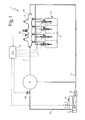
- numeral 1 indicates as a whole a common-rail type system for direct fuel injection into an internal combustion engine 2 provided with four cylinders 3.
- the injection system 1 comprises four injectors 4, each of which has a hydraulic needle actuation system (i.e. the needle actuation is hydraulically servo-assisted) and is adapted to directly inject the fuel into a respective cylinder 3 of engine 2 and to receive the pressurized fuel from a common rail 5.
- a hydraulic needle actuation system i.e. the needle actuation is hydraulically servo-assisted
- System 1 comprises a high pressure pump 6 which feds fuel to the common rail 5 by means of a delivery duct 7 and is directly actuated by a driving shaft of engine 2 by means of a mechanical transmission with an actuation frequency being directly proportional to the rotation speed of the driving shaft.
- the high pressure pump 6 is fed in turn by a low pressure pump 8 of volumetric type by means of a duct 9 of the high pressure pump 6.
- the low pressure pump 8 is arranged inside a fuel tank 10, into which a recirculation duct 11 for the excess fuel of the injection system 1 leads, which duct receives the excess fuel from the injectors 4, from a mechanical pressure safety valve 12 which is hydraulically coupled to the common rail 5, and from a lubrication duct of the high pressure pump 6 (into which the fuel used to lubricate the high pressure pump 6 is discharged).
- the pressure safety valve 12 is calibrated to automatically open when the fuel pressure P rail in the common rail 5 exceeds a safety value which ensures the tightness and safety of the injection system 1.
- Each injector 4 is adapted to inject a variable amount of fuel into the corresponding cylinder 3 under the control of an electronic control unit 14.
- injectors 4 have a hydraulic needle actuation and are thus connected to the recirculation duct 11, which has a pressure slightly higher than ambient pressure, and leads upstream of the low pressure pump 8 directly into the tank 10.
- each injector 4 absorbs a certain amount of pressurized fuel, which is discharged into the recirculation duct 11.
- a recirculation valve 13 which is a one-way valve (i.e. only allows a flow of fuel into the tank 10), is entirely passive (i.e. free from controllable actuators), and is calibrated to open when the pressure difference at its ends is higher than a predetermined intervention threshold value.
- the pressure of the fuel inside the recirculation duct 11 remains, in use, approximately equal to a predetermined value (typically between 1.3 and 1.8 bars) depending on the intervention threshold value of the recirculation valve 13 itself; thereby, the control of the injectors 4 is simpler, as the fuel pressure inside the recirculation duct 11 is constant (stable) and known (i.e. the fuel pressure difference at the ends of the injectors 4 is constant and known).
- the electronic control unit 14 is connected to a pressure sensor 15, which detects the actual fuel pressure P rail inside the common rail 5 and, according to the actual fuel pressure P rail inside the common rail 5, feedback controls the delivery of the low pressure pump 8; thereby, the actual fuel pressure P rail inside the common rail 5 is maintained equal to a desired pressure P railref which generally varies over time according to the engine point (i.e. according to the operating conditions of the internal combustion engine 2). Furthermore, the electronic control unit 14 is connected to a pressure sensor 16, which detects the actual pressure P fuelLP of the fuel inside the duct 9 (and thus between the delivery of the low pressure pump 8 and the intake of the high pressure pump 6) and immediately upstream of the high pressure pump 6.
- the electronic control unit 14 determines the desired pressure P railref of the fuel inside the common rail 5 according to the engine point, and thus regulates the delivery of the low pressure pump 8 towards the high pressure pump 6 to pursue the desired fuel pressure P railref inside the common rail 5 and so as to obtain a corresponding regulation of the delivery of the high pressure pump 6 towards the common rail 5.
- the electronic control unit 14 pursues the desired fuel pressure P railref inside the common rail 5.
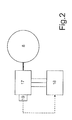
- the low pressure pump 8 is actuated by an electric motor 17, which is controlled by an electronic device comprising an electronic power converter 18, which is powered from a battery (not shown) of the vehicle.
- the electric motor 17 is provided with a speed sensor 19, which measures the actual rotation speed ⁇ P of the electric motor 17 and thus of the low pressure pump 8.
- the low pressure pump 8 is of the volumetric type, and therefore the delivery of the low pressure pump 8 towards the high pressure pump 6 is directly proportional to the actual rotation speed ⁇ P of the electric motor 17, and thus of the low pressure pump 8.
- the electronic power converter 18 is arranged close to tank 10 (i.e. close to the electric motor 17 which is integrated and forms a unit with the low pressure pump 8), and thus is physically separate from the electronic control unit 14; therefore, the electronic control unit 14 is connected to the electronic power converter 18 by means of a data line (e.g. the vehicle BUS working according to CAN (Car Area Network) protocol).
- a data line e.g. the vehicle BUS working according to CAN (Car Area Network) protocol.
- CAN Car Area Network
- the electronic power converter 18 is completely integrated with the electric motor 17 and the low pressure pump 8, i.e. forms an indivisible unit with the electric motor 17 and the low pressure pump 8.
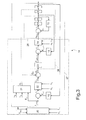
- control logic of the injection system 1 implemented in the electronic control unit 14 is illustrated below with reference to figure 3 .
- the electronic control unit 14 comprises a calculation block 20, which determines the desired pressure P railref of the fuel inside the common rail 5 according to the engine point, and in particular according to a rotation speed ⁇ E of the internal combustion engine 2, to a load L E of the internal combustion engine 2, to a temperature T H2O of a coolant of the internal combustion engine 2, and to a temperature of the fuel T fuel inside the tank 10 (or, alternatively, in other points of the low pressure fuel circuit or of the high pressure fuel circuit).
- the calculation block 20 may implement an experimentally determined model of engine 2 and/or an experimentally determined map.
- a desired delivery Q ref of the high pressure pump 6 towards the common rail 5 is determined downstream of the calculation block 20, according to the desired pressure P railref of the fuel inside the common rail 5; as described below, the desired delivery Q ref of the high pressure pump 6 towards the common rail 5 is used to control the low pressure pump 8.
- a regulator 21 determines an open loop contribution Q OL according to the desired pressure P railref of the fuel inside the common rail 5, to the rotation speed ⁇ E of the internal combustion engine 2, and to the load L E of the internal combustion engine 2.
- a closed loop contribution Q CL is determined according to a pressure error ⁇ r calculated by making the difference between the desired pressure P railref of the fuel inside the common rail 5 and the actual pressure P rail of the fuel inside the common rail 5 (measured by pressure sensor 15); in particular, the closed loop contribution Q CL is determined by a regulator 22 (typically of PID type), which takes into account the rotation speed ⁇ E of the internal combustion engine 2 and the load L E of the internal combustion engine 2.
- the closed loop contribution Q CL is algebraically added (i.e. the sign being taken into account) to the open loop contribution Q OL to obtain the desired delivery Q ref of the high pressure pump 6 towards the common rail 5.
- the function of the closed loop contribution Q CL is to pursue the desired pressure P railref of the fuel inside the common rail 5 by means of a classic feedback control; instead, the function of the open loop contribution Q OL is to anticipate the future variation of the desired pressure P railref of the fuel inside the common rail 5 so as to increase the control response promptness.
- a calculation block 23 determines a desired pressure P fuelLPref of the fuel (immediately) upstream of the high pressure pump 6 according to the desired delivery Q ref of the high pressure pump 6 towards the common rail 5; as described below, the desired pressure P fuelLPref of the fuel upstream of the high pressure pump 6 is used to control the low pressure pump 8.
- a pressure error is calculated ⁇ f by making the difference between the desired pressure P fuelLPref of the fuel upstream of the high pressure pump 6 and the actual pressure P fuelLP of the fuel upstream of the high pressure pump 6 (measured by the pressure sensor 16); the pressure error ⁇ f is processed by a regulator 24 (typically of PID type), which also takes into account the rotation speed ⁇ E of the internal combustion engine 2 and the load L E of the internal combustion engine 2, and determines a desired speed ⁇ Pref of the low pressure pump 8.
- a regulator 24 typically of PID type
- the desired speed ⁇ Pref of the low pressure pump 8 is determined by the regulator 24 according to the desired pressure P fuelLPref of the fuel upstream of the high pressure pump 6 (or more precisely according to the pressure error ⁇ f , which depends on the desired pressure P fuelLPref of the fuel upstream of the high pressure pump 6), to a rotation speed ⁇ E of the internal combustion engine 2, and to a load L E of the internal combustion engine 2.
- the low pressure pump 8 is controlled according to the desired speed ⁇ Pref of the low pressure pump 8; in particular, a speed error ⁇ r is calculated by making the difference between the desired speed ⁇ Pref of the low pressure pump 8 and the actual speed ⁇ p of the low pressure pump 8 (measured by the speed sensor 19). Thereby, the low pressure pump 8 is feedback controlled using the actual speed ⁇ p of the low pressure pump 8 as a feedback variable.
- Regulators 21, 22 and 24 and calculation block 23 may implement experimentally determined models and/or experimentally determined maps.
- an internal feedback control loop 25 which uses the actual speed ⁇ p of the low pressure pump 8 as a feedback variable
- an intermediate feedback control loop 26 which uses the actual pressure P fuelLP of the fuel upstream of the high pressure pump 6 as a feedback variable
- an external feedback control loop 27 which uses the actual pressure P rail of the fuel inside the common rail 5 as a feedback variable.
- a further feedback control loop which uses the intensity (or duty cycle) of an electric current supplied to the electric motor 17 as a feedback variable, is normally present.
- the electronic power converter 18 controls the electric power supplied to the electric motor 17, thus allowing the actual speed ⁇ p of the low pressure pump 8 to be regulated by means of a PWM (Pulse Width Modulation) type technique, which includes chopping the electric voltage applied to the electric motor 17 over time.
- PWM Pulse Width Modulation
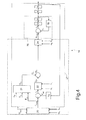
- the intermediate feedback control loop 26, which uses the actual pressure P fuelLP of the fuel upstream of the high pressure pump 6 as a feedback variable, is eliminated; in this embodiment, regulator 24 determines the desired speed ⁇ Pref of the low pressure pump 8 in open loop, directly according to the desired delivery Q ref of the high pressure pump 6 towards the common rail 5. In particular, regulator 24 determines the desired speed ⁇ Pref of the low pressure pump 8 according to the desired delivery Q ref of the high pressure pump 6 towards the common rail 5, to the rotation speed ⁇ E of the internal combustion engine 2, and to the load L E of the internal combustion engine 2.
- control logic shown in the diagram in figure 4 is simpler than the control logic shown in the diagram in figure 3 , and does not require measuring the actual fuel pressure P fuelLP upstream of the high pressure pump 6; however, the control logic shown in the diagram in figure 4 has a lower dynamic performance (i.e. it is slower in reacting to variations) than the control logic shown in the diagram in figure 3 .
- the above-described mode of controlling the injection system 1 has many advantages.
- the above-described mode of controlling the injection system 1 is simpler and more cost-effective to be implemented than a known control mode in which an on-off valve arranged upstream of the high pressure pump 6 is inlcuded; indeed, the industrial cost of an on-off valve and of the corresponding control logic is higher than the industrial cost of the control electronics of the electric motor 17 of the low pressure pump 8 required by the above-described control mode.
- the above-described mode of controlling the injection system 1 allows to rapidly and accurately pursue the desired pressure P railref of the fuel inside the common rail 5 even in the presence of sudden variations; hence, the above-described control mode substantially has the same dynamic performance as a known control mode including the presence of an on-off valve arranged upstream of the high pressure pump 6.
- the above-described mode of controlling the injection system 1 allows to increase the overall energy efficiency, because in the above-described control mode, the low pressure pump 8 is controlled to pump each time only the amount of fuel needed to maintain the actual pressure P rail of the fuel inside the common rail 5 equal to the desired pressure P railref , and thus when the engine 2 is not at maximum load (i.e. over nearly all the operating time of engine 2), the fuel delivery of the low pressure pump 8 is lower (even much lower) than its nominal fuel delivery (corresponding to the full control voltage, e.g. 14 Volts).
- the low pressure pump 8 is controlled to pump the nominal fuel delivery at each instant (and thus also when the engine 2 is idling); in this case, the excess fuel pumped by the low pressure pump 8 (i.e. the fuel which is not pumped by the high pressure pump 6 towards the common rail 5) is discharged into the tank 10.
- the low pressure pump 8 is controlled to pump the nominal fuel delivery at each instant; therefore, the low pressure pump 8 and the corresponding electric motor 17 should be dimensioned to continuously work at nominal fuel delivery (determined so as to be always in excess as compared to the maximum possible consumption of the high pressure pump 6).
- the low pressure pump 8 is controlled to pump each time only the amount of fuel needed to maintain the actual pressure P rail of the fuel inside the common rail 5 equal to the desired pressure P railref ; therefore, the low pressure pump 8 and the corresponding electric motor 17 may be dimensioned to continuously work at a fuel delivery which is much lower than nominal delivery (as previously defined), with an apparent cost saving and a reduction of weight and dimensions.
- a pressure regulating valve should be integrated in the intake system of the high pressure pump 6 itself; the integration of the pressure regulating valve in the intake system of the high pressure pump 6 is complex and thus costly due to the little available space inside the high pressure pump 6.
- the high pressure pump 6 does not require the presence of any pressure regulating valve in the intake system.
- the recirculation valve 13 which regulates the re-introduction of fuel into the tank 10 and is provided in the above-described control mode, is a completely passive valve, is calibrated to work at low pressures (e.g.
- the recirculation valve 13 is simple and cost-effective to be implemented and assembled.
- the installation of the recirculation valve 13 is simpler and more cost-effective than the installation of a pressure regulating valve in the intake system of the high pressure pump 6, as required in a known control mode in which an on-off valve arranged upstream of the highpressure pump 6 is included.
Landscapes
- Engineering & Computer Science (AREA)
- Chemical & Material Sciences (AREA)
- Combustion & Propulsion (AREA)
- Mechanical Engineering (AREA)
- General Engineering & Computer Science (AREA)
- Fuel-Injection Apparatus (AREA)
- Electrical Control Of Air Or Fuel Supplied To Internal-Combustion Engine (AREA)
Applications Claiming Priority (1)
| Application Number | Priority Date | Filing Date | Title |
|---|---|---|---|
| ITBO2009A000545A IT1395038B1 (it) | 2009-08-12 | 2009-08-12 | Metodo di controllo di un impianto di iniezione diretta di tipo common-rail |
Publications (3)
| Publication Number | Publication Date |
|---|---|
| EP2284380A2 true EP2284380A2 (de) | 2011-02-16 |
| EP2284380A3 EP2284380A3 (de) | 2013-08-28 |
| EP2284380B1 EP2284380B1 (de) | 2017-11-29 |
Family
ID=41820557
Family Applications (1)
| Application Number | Title | Priority Date | Filing Date |
|---|---|---|---|
| EP10172447.4A Not-in-force EP2284380B1 (de) | 2009-08-12 | 2010-08-11 | Verfahren zur Steuerung eines Common-Rail-Direkteinspritzungssystems |
Country Status (2)
| Country | Link |
|---|---|
| EP (1) | EP2284380B1 (de) |
| IT (1) | IT1395038B1 (de) |
Cited By (8)
| Publication number | Priority date | Publication date | Assignee | Title |
|---|---|---|---|---|
| EP2762718A4 (de) * | 2011-09-28 | 2015-12-16 | Toyota Motor Co Ltd | System zur steuerung der kraftstoffeinspritzung in einen verbrennungsmotor |
| EP2728159A4 (de) * | 2011-07-01 | 2016-06-15 | Toyota Motor Co Ltd | System zur steuerung der kraftstoffeinspritzung in einen verbrennungsmotor |
| EP2634411A4 (de) * | 2010-10-27 | 2016-08-10 | Toyota Motor Co Ltd | Kraftstoffeinspritzsteuersystem für verbrennungsmotoren |
| CN106286061A (zh) * | 2015-06-25 | 2017-01-04 | 福特环球技术公司 | 用于燃料喷射的系统和方法 |
| US9657680B2 (en) | 2014-12-30 | 2017-05-23 | Ford Global Technologies, Llc | Zero flow lubrication for a high pressure fuel pump |
| CN109555609A (zh) * | 2017-09-25 | 2019-04-02 | 丰田自动车株式会社 | 内燃机的燃料喷射控制装置及其工作方法 |
| CN112240260A (zh) * | 2019-07-18 | 2021-01-19 | 马瑞利欧洲公司 | 控制用于直接喷射系统的高压燃料泵的方法 |
| CN107131066B (zh) * | 2016-02-29 | 2021-09-10 | 福特环球技术公司 | 用于燃料轨泄压的方法和系统 |
Citations (3)
| Publication number | Priority date | Publication date | Assignee | Title |
|---|---|---|---|---|
| EP0481964A2 (de) | 1988-11-24 | 1992-04-22 | Nippondenso Co., Ltd. | Hochdruckpumpe mit veränderlichem Abfluss |
| US6116870A (en) | 1996-10-29 | 2000-09-12 | Robert Bosch Gmbh | High pressure pump with solenoid operated valve |
| EP1612402A1 (de) | 2004-06-30 | 2006-01-04 | C.R.F. Societa' Consortile per Azioni | Hochdruckpumpe mit variabler Förderrate für ein Brennstoffeinspritzsystem |
Family Cites Families (9)
| Publication number | Priority date | Publication date | Assignee | Title |
|---|---|---|---|---|
| DE19548278B4 (de) * | 1995-12-22 | 2007-09-13 | Robert Bosch Gmbh | Verfahren und Vorrichtung zur Steuerung einer Brennkraftmaschine |
| FR2753488B1 (fr) * | 1996-09-17 | 1998-10-30 | Renault | Systeme d'alimentation en air d'un moteur a combustion interne |
| DE19731201C2 (de) * | 1997-07-21 | 2002-04-11 | Siemens Ag | Verfahren zum Regeln des Kraftstoffdruckes in einem Kraftstoffspeicher |
| EP1405998A1 (de) * | 1999-12-09 | 2004-04-07 | International Engine Intellectual Property Company, LLC. | Regelung der Abgasrückführung und Ereignisüberwachung in einer selbstgezündeten Brennkraftmaschine |
| DE10162989C1 (de) * | 2001-12-20 | 2003-10-09 | Siemens Ag | Schaltungsanordnung zum Regeln einer regelbaren Kraftstoffpumpe, Verfahren zum Regeln einer Förderleistung und Verfahren zum Überprüfen der Funktionsfähigkeit einer regelbaren Kraftstoffpumpe |
| US7207319B2 (en) * | 2004-03-11 | 2007-04-24 | Denso Corporation | Fuel injection system having electric low-pressure pump |
| DE102004045738B4 (de) * | 2004-09-21 | 2013-05-29 | Continental Automotive Gmbh | Verfahren und Vorrichtung zum Steuern einer Brennkraftmaschine |
| JP4668150B2 (ja) * | 2006-08-31 | 2011-04-13 | トヨタ自動車株式会社 | 可変バルブタイミング装置 |
| JP4528339B2 (ja) * | 2008-05-16 | 2010-08-18 | エムエーエヌ・ディーゼル・フィリアル・アフ・エムエーエヌ・ディーゼル・エスイー・ティスクランド | 複数の可変ターボチャージャーを備える大型2サイクルディーゼルエンジン |
-
2009
- 2009-08-12 IT ITBO2009A000545A patent/IT1395038B1/it active
-
2010
- 2010-08-11 EP EP10172447.4A patent/EP2284380B1/de not_active Not-in-force
Patent Citations (3)
| Publication number | Priority date | Publication date | Assignee | Title |
|---|---|---|---|---|
| EP0481964A2 (de) | 1988-11-24 | 1992-04-22 | Nippondenso Co., Ltd. | Hochdruckpumpe mit veränderlichem Abfluss |
| US6116870A (en) | 1996-10-29 | 2000-09-12 | Robert Bosch Gmbh | High pressure pump with solenoid operated valve |
| EP1612402A1 (de) | 2004-06-30 | 2006-01-04 | C.R.F. Societa' Consortile per Azioni | Hochdruckpumpe mit variabler Förderrate für ein Brennstoffeinspritzsystem |
Cited By (12)
| Publication number | Priority date | Publication date | Assignee | Title |
|---|---|---|---|---|
| EP2634411A4 (de) * | 2010-10-27 | 2016-08-10 | Toyota Motor Co Ltd | Kraftstoffeinspritzsteuersystem für verbrennungsmotoren |
| EP2728159A4 (de) * | 2011-07-01 | 2016-06-15 | Toyota Motor Co Ltd | System zur steuerung der kraftstoffeinspritzung in einen verbrennungsmotor |
| EP2762718A4 (de) * | 2011-09-28 | 2015-12-16 | Toyota Motor Co Ltd | System zur steuerung der kraftstoffeinspritzung in einen verbrennungsmotor |
| US9657680B2 (en) | 2014-12-30 | 2017-05-23 | Ford Global Technologies, Llc | Zero flow lubrication for a high pressure fuel pump |
| US10161347B2 (en) | 2014-12-30 | 2018-12-25 | Ford Global Technologies, Llc | Zero flow lubrication for a high pressure fuel pump |
| CN106286061A (zh) * | 2015-06-25 | 2017-01-04 | 福特环球技术公司 | 用于燃料喷射的系统和方法 |
| CN106286061B (zh) * | 2015-06-25 | 2020-04-14 | 福特环球技术公司 | 用于燃料喷射的系统和方法 |
| CN107131066B (zh) * | 2016-02-29 | 2021-09-10 | 福特环球技术公司 | 用于燃料轨泄压的方法和系统 |
| CN109555609A (zh) * | 2017-09-25 | 2019-04-02 | 丰田自动车株式会社 | 内燃机的燃料喷射控制装置及其工作方法 |
| CN109555609B (zh) * | 2017-09-25 | 2021-10-26 | 丰田自动车株式会社 | 内燃机的燃料喷射控制装置及其工作方法 |
| CN112240260A (zh) * | 2019-07-18 | 2021-01-19 | 马瑞利欧洲公司 | 控制用于直接喷射系统的高压燃料泵的方法 |
| CN112240260B (zh) * | 2019-07-18 | 2024-05-10 | 马瑞利欧洲公司 | 控制用于直接喷射系统的高压燃料泵的方法 |
Also Published As
| Publication number | Publication date |
|---|---|
| ITBO20090545A1 (it) | 2011-02-13 |
| EP2284380A3 (de) | 2013-08-28 |
| EP2284380B1 (de) | 2017-11-29 |
| IT1395038B1 (it) | 2012-09-05 |
Similar Documents
| Publication | Publication Date | Title |
|---|---|---|
| EP2284380B1 (de) | Verfahren zur Steuerung eines Common-Rail-Direkteinspritzungssystems | |
| US9587579B2 (en) | Current pulsing control methods for lift fuel pumps | |
| DE102008051082A1 (de) | Saugpumpensteuerung für eine Direkteinspritzkraftstoffanlage mit zwei Pumpen | |
| US8186154B2 (en) | Rotary flow control valve with energy recovery | |
| CN104884818B (zh) | 流体泵组件的比例流量控制 | |
| US20040187834A1 (en) | Power system with an integrated lubrication circuit | |
| US8080888B1 (en) | Hydraulic generator drive system | |
| US8826889B2 (en) | Pressure regulating valve for regulating the pressure in a high-pressure reservoir | |
| CN101403358A (zh) | 一种基于容积效率的提升泵的控制方法 | |
| US6976473B2 (en) | Fuel injection system for an internal combustion engine | |
| CN101408137B (zh) | 有助于改进发动机起动的燃料系统 | |
| US6152107A (en) | Device for controlling fuel injection in cold engine temperatures | |
| EP2762718A1 (de) | System zur steuerung der kraftstoffeinspritzung in einen verbrennungsmotor | |
| EP1147313A1 (de) | Ventilsystem zur regelung des brennstoffansaugdrucks einer hochdruckpumpe | |
| DE102009004590A1 (de) | Saugpumpensystem für ein Kraftstoffdirekteinspritzsystem | |
| US20150354491A1 (en) | Adjusting pump volume commands for direct injection fuel pumps | |
| JP2007023944A (ja) | 燃料噴射装置および燃料噴射装置の異常検出方法 | |
| US20050056258A1 (en) | Fuel supply apparatus and fuel pressure regulating method for internal combustion engine | |
| US20180030916A1 (en) | System for controlling fuel rail pressure in a common rail direct fuel injection system | |
| EP2728159A1 (de) | System zur steuerung der kraftstoffeinspritzung in einen verbrennungsmotor | |
| US6712043B2 (en) | Actuating fluid control system | |
| WO2008067622A2 (en) | Method and apparatus for fuel flow control in an internal combustion engine | |
| JP2008121563A (ja) | 内燃機関の燃料供給装置 | |
| US20140165965A1 (en) | Fuel supply system with accumulator | |
| CN204851451U (zh) | 共轨式柴油机电控燃油喷射系统的控制装置 |
Legal Events
| Date | Code | Title | Description |
|---|---|---|---|
| PUAI | Public reference made under article 153(3) epc to a published international application that has entered the european phase |
Free format text: ORIGINAL CODE: 0009012 |
|
| AK | Designated contracting states |
Kind code of ref document: A2 Designated state(s): AL AT BE BG CH CY CZ DE DK EE ES FI FR GB GR HR HU IE IS IT LI LT LU LV MC MK MT NL NO PL PT RO SE SI SK SM TR |
|
| AX | Request for extension of the european patent |
Extension state: BA ME RS |
|
| PUAL | Search report despatched |
Free format text: ORIGINAL CODE: 0009013 |
|
| AK | Designated contracting states |
Kind code of ref document: A3 Designated state(s): AL AT BE BG CH CY CZ DE DK EE ES FI FR GB GR HR HU IE IS IT LI LT LU LV MC MK MT NL NO PL PT RO SE SI SK SM TR |
|
| AX | Request for extension of the european patent |
Extension state: BA ME RS |
|
| RIC1 | Information provided on ipc code assigned before grant |
Ipc: F02M 55/02 20060101ALI20130722BHEP Ipc: F02M 63/02 20060101ALI20130722BHEP Ipc: F02D 41/14 20060101ALI20130722BHEP Ipc: F02D 41/38 20060101AFI20130722BHEP |
|
| 17P | Request for examination filed |
Effective date: 20130923 |
|
| GRAP | Despatch of communication of intention to grant a patent |
Free format text: ORIGINAL CODE: EPIDOSNIGR1 |
|
| INTG | Intention to grant announced |
Effective date: 20170614 |
|
| GRAS | Grant fee paid |
Free format text: ORIGINAL CODE: EPIDOSNIGR3 |
|
| GRAA | (expected) grant |
Free format text: ORIGINAL CODE: 0009210 |
|
| AK | Designated contracting states |
Kind code of ref document: B1 Designated state(s): AL AT BE BG CH CY CZ DE DK EE ES FI FR GB GR HR HU IE IS IT LI LT LU LV MC MK MT NL NO PL PT RO SE SI SK SM TR |
|
| REG | Reference to a national code |
Ref country code: GB Ref legal event code: FG4D |
|
| REG | Reference to a national code |
Ref country code: CH Ref legal event code: EP |
|
| REG | Reference to a national code |
Ref country code: AT Ref legal event code: REF Ref document number: 950626 Country of ref document: AT Kind code of ref document: T Effective date: 20171215 |
|
| REG | Reference to a national code |
Ref country code: IE Ref legal event code: FG4D |
|
| REG | Reference to a national code |
Ref country code: DE Ref legal event code: R096 Ref document number: 602010046996 Country of ref document: DE |
|
| REG | Reference to a national code |
Ref country code: NL Ref legal event code: MP Effective date: 20171129 |
|
| REG | Reference to a national code |
Ref country code: LT Ref legal event code: MG4D |
|
| REG | Reference to a national code |
Ref country code: AT Ref legal event code: MK05 Ref document number: 950626 Country of ref document: AT Kind code of ref document: T Effective date: 20171129 |
|
| PG25 | Lapsed in a contracting state [announced via postgrant information from national office to epo] |
Ref country code: LT Free format text: LAPSE BECAUSE OF FAILURE TO SUBMIT A TRANSLATION OF THE DESCRIPTION OR TO PAY THE FEE WITHIN THE PRESCRIBED TIME-LIMIT Effective date: 20171129 Ref country code: FI Free format text: LAPSE BECAUSE OF FAILURE TO SUBMIT A TRANSLATION OF THE DESCRIPTION OR TO PAY THE FEE WITHIN THE PRESCRIBED TIME-LIMIT Effective date: 20171129 Ref country code: ES Free format text: LAPSE BECAUSE OF FAILURE TO SUBMIT A TRANSLATION OF THE DESCRIPTION OR TO PAY THE FEE WITHIN THE PRESCRIBED TIME-LIMIT Effective date: 20171129 Ref country code: SE Free format text: LAPSE BECAUSE OF FAILURE TO SUBMIT A TRANSLATION OF THE DESCRIPTION OR TO PAY THE FEE WITHIN THE PRESCRIBED TIME-LIMIT Effective date: 20171129 Ref country code: NO Free format text: LAPSE BECAUSE OF FAILURE TO SUBMIT A TRANSLATION OF THE DESCRIPTION OR TO PAY THE FEE WITHIN THE PRESCRIBED TIME-LIMIT Effective date: 20180228 |
|
| PG25 | Lapsed in a contracting state [announced via postgrant information from national office to epo] |
Ref country code: AT Free format text: LAPSE BECAUSE OF FAILURE TO SUBMIT A TRANSLATION OF THE DESCRIPTION OR TO PAY THE FEE WITHIN THE PRESCRIBED TIME-LIMIT Effective date: 20171129 Ref country code: GR Free format text: LAPSE BECAUSE OF FAILURE TO SUBMIT A TRANSLATION OF THE DESCRIPTION OR TO PAY THE FEE WITHIN THE PRESCRIBED TIME-LIMIT Effective date: 20180301 Ref country code: BG Free format text: LAPSE BECAUSE OF FAILURE TO SUBMIT A TRANSLATION OF THE DESCRIPTION OR TO PAY THE FEE WITHIN THE PRESCRIBED TIME-LIMIT Effective date: 20180228 Ref country code: HR Free format text: LAPSE BECAUSE OF FAILURE TO SUBMIT A TRANSLATION OF THE DESCRIPTION OR TO PAY THE FEE WITHIN THE PRESCRIBED TIME-LIMIT Effective date: 20171129 Ref country code: LV Free format text: LAPSE BECAUSE OF FAILURE TO SUBMIT A TRANSLATION OF THE DESCRIPTION OR TO PAY THE FEE WITHIN THE PRESCRIBED TIME-LIMIT Effective date: 20171129 |
|
| PG25 | Lapsed in a contracting state [announced via postgrant information from national office to epo] |
Ref country code: NL Free format text: LAPSE BECAUSE OF FAILURE TO SUBMIT A TRANSLATION OF THE DESCRIPTION OR TO PAY THE FEE WITHIN THE PRESCRIBED TIME-LIMIT Effective date: 20171129 |
|
| REG | Reference to a national code |
Ref country code: FR Ref legal event code: PLFP Year of fee payment: 9 |
|
| PG25 | Lapsed in a contracting state [announced via postgrant information from national office to epo] |
Ref country code: SK Free format text: LAPSE BECAUSE OF FAILURE TO SUBMIT A TRANSLATION OF THE DESCRIPTION OR TO PAY THE FEE WITHIN THE PRESCRIBED TIME-LIMIT Effective date: 20171129 Ref country code: CY Free format text: LAPSE BECAUSE OF FAILURE TO SUBMIT A TRANSLATION OF THE DESCRIPTION OR TO PAY THE FEE WITHIN THE PRESCRIBED TIME-LIMIT Effective date: 20171129 Ref country code: EE Free format text: LAPSE BECAUSE OF FAILURE TO SUBMIT A TRANSLATION OF THE DESCRIPTION OR TO PAY THE FEE WITHIN THE PRESCRIBED TIME-LIMIT Effective date: 20171129 Ref country code: DK Free format text: LAPSE BECAUSE OF FAILURE TO SUBMIT A TRANSLATION OF THE DESCRIPTION OR TO PAY THE FEE WITHIN THE PRESCRIBED TIME-LIMIT Effective date: 20171129 Ref country code: CZ Free format text: LAPSE BECAUSE OF FAILURE TO SUBMIT A TRANSLATION OF THE DESCRIPTION OR TO PAY THE FEE WITHIN THE PRESCRIBED TIME-LIMIT Effective date: 20171129 |
|
| REG | Reference to a national code |
Ref country code: DE Ref legal event code: R097 Ref document number: 602010046996 Country of ref document: DE |
|
| PG25 | Lapsed in a contracting state [announced via postgrant information from national office to epo] |
Ref country code: PL Free format text: LAPSE BECAUSE OF FAILURE TO SUBMIT A TRANSLATION OF THE DESCRIPTION OR TO PAY THE FEE WITHIN THE PRESCRIBED TIME-LIMIT Effective date: 20171129 Ref country code: SM Free format text: LAPSE BECAUSE OF FAILURE TO SUBMIT A TRANSLATION OF THE DESCRIPTION OR TO PAY THE FEE WITHIN THE PRESCRIBED TIME-LIMIT Effective date: 20171129 Ref country code: RO Free format text: LAPSE BECAUSE OF FAILURE TO SUBMIT A TRANSLATION OF THE DESCRIPTION OR TO PAY THE FEE WITHIN THE PRESCRIBED TIME-LIMIT Effective date: 20171129 |
|
| PLBE | No opposition filed within time limit |
Free format text: ORIGINAL CODE: 0009261 |
|
| STAA | Information on the status of an ep patent application or granted ep patent |
Free format text: STATUS: NO OPPOSITION FILED WITHIN TIME LIMIT |
|
| 26N | No opposition filed |
Effective date: 20180830 |
|
| PG25 | Lapsed in a contracting state [announced via postgrant information from national office to epo] |
Ref country code: SI Free format text: LAPSE BECAUSE OF FAILURE TO SUBMIT A TRANSLATION OF THE DESCRIPTION OR TO PAY THE FEE WITHIN THE PRESCRIBED TIME-LIMIT Effective date: 20171129 |
|
| PG25 | Lapsed in a contracting state [announced via postgrant information from national office to epo] |
Ref country code: MC Free format text: LAPSE BECAUSE OF FAILURE TO SUBMIT A TRANSLATION OF THE DESCRIPTION OR TO PAY THE FEE WITHIN THE PRESCRIBED TIME-LIMIT Effective date: 20171129 |
|
| REG | Reference to a national code |
Ref country code: CH Ref legal event code: PL |
|
| GBPC | Gb: european patent ceased through non-payment of renewal fee |
Effective date: 20180811 |
|
| PG25 | Lapsed in a contracting state [announced via postgrant information from national office to epo] |
Ref country code: LU Free format text: LAPSE BECAUSE OF NON-PAYMENT OF DUE FEES Effective date: 20180811 Ref country code: LI Free format text: LAPSE BECAUSE OF NON-PAYMENT OF DUE FEES Effective date: 20180831 Ref country code: CH Free format text: LAPSE BECAUSE OF NON-PAYMENT OF DUE FEES Effective date: 20180831 |
|
| REG | Reference to a national code |
Ref country code: BE Ref legal event code: MM Effective date: 20180831 |
|
| REG | Reference to a national code |
Ref country code: IE Ref legal event code: MM4A |
|
| PG25 | Lapsed in a contracting state [announced via postgrant information from national office to epo] |
Ref country code: IE Free format text: LAPSE BECAUSE OF NON-PAYMENT OF DUE FEES Effective date: 20180811 |
|
| PG25 | Lapsed in a contracting state [announced via postgrant information from national office to epo] |
Ref country code: BE Free format text: LAPSE BECAUSE OF NON-PAYMENT OF DUE FEES Effective date: 20180831 |
|
| PG25 | Lapsed in a contracting state [announced via postgrant information from national office to epo] |
Ref country code: GB Free format text: LAPSE BECAUSE OF NON-PAYMENT OF DUE FEES Effective date: 20180811 |
|
| PG25 | Lapsed in a contracting state [announced via postgrant information from national office to epo] |
Ref country code: MT Free format text: LAPSE BECAUSE OF NON-PAYMENT OF DUE FEES Effective date: 20180811 |
|
| PG25 | Lapsed in a contracting state [announced via postgrant information from national office to epo] |
Ref country code: TR Free format text: LAPSE BECAUSE OF FAILURE TO SUBMIT A TRANSLATION OF THE DESCRIPTION OR TO PAY THE FEE WITHIN THE PRESCRIBED TIME-LIMIT Effective date: 20171129 |
|
| PG25 | Lapsed in a contracting state [announced via postgrant information from national office to epo] |
Ref country code: PT Free format text: LAPSE BECAUSE OF FAILURE TO SUBMIT A TRANSLATION OF THE DESCRIPTION OR TO PAY THE FEE WITHIN THE PRESCRIBED TIME-LIMIT Effective date: 20171129 Ref country code: HU Free format text: LAPSE BECAUSE OF FAILURE TO SUBMIT A TRANSLATION OF THE DESCRIPTION OR TO PAY THE FEE WITHIN THE PRESCRIBED TIME-LIMIT; INVALID AB INITIO Effective date: 20100811 |
|
| PG25 | Lapsed in a contracting state [announced via postgrant information from national office to epo] |
Ref country code: MK Free format text: LAPSE BECAUSE OF NON-PAYMENT OF DUE FEES Effective date: 20171129 |
|
| PG25 | Lapsed in a contracting state [announced via postgrant information from national office to epo] |
Ref country code: AL Free format text: LAPSE BECAUSE OF FAILURE TO SUBMIT A TRANSLATION OF THE DESCRIPTION OR TO PAY THE FEE WITHIN THE PRESCRIBED TIME-LIMIT Effective date: 20171129 Ref country code: IS Free format text: LAPSE BECAUSE OF FAILURE TO SUBMIT A TRANSLATION OF THE DESCRIPTION OR TO PAY THE FEE WITHIN THE PRESCRIBED TIME-LIMIT Effective date: 20180329 |
|
| PGFP | Annual fee paid to national office [announced via postgrant information from national office to epo] |
Ref country code: IT Payment date: 20220720 Year of fee payment: 13 |
|
| PGFP | Annual fee paid to national office [announced via postgrant information from national office to epo] |
Ref country code: FR Payment date: 20220721 Year of fee payment: 13 |
|
| PGFP | Annual fee paid to national office [announced via postgrant information from national office to epo] |
Ref country code: DE Payment date: 20230720 Year of fee payment: 14 |
|
| PG25 | Lapsed in a contracting state [announced via postgrant information from national office to epo] |
Ref country code: IT Free format text: LAPSE BECAUSE OF NON-PAYMENT OF DUE FEES Effective date: 20230811 Ref country code: FR Free format text: LAPSE BECAUSE OF NON-PAYMENT OF DUE FEES Effective date: 20230831 |
|
| REG | Reference to a national code |
Ref country code: DE Ref legal event code: R119 Ref document number: 602010046996 Country of ref document: DE |
|
| PG25 | Lapsed in a contracting state [announced via postgrant information from national office to epo] |
Ref country code: DE Free format text: LAPSE BECAUSE OF NON-PAYMENT OF DUE FEES Effective date: 20250301 |