EP2284382A2 - Système d'alimentation - Google Patents
Système d'alimentation Download PDFInfo
- Publication number
- EP2284382A2 EP2284382A2 EP10172234A EP10172234A EP2284382A2 EP 2284382 A2 EP2284382 A2 EP 2284382A2 EP 10172234 A EP10172234 A EP 10172234A EP 10172234 A EP10172234 A EP 10172234A EP 2284382 A2 EP2284382 A2 EP 2284382A2
- Authority
- EP
- European Patent Office
- Prior art keywords
- power
- voltage
- power supply
- connecting bus
- unit
- Prior art date
- Legal status (The legal status is an assumption and is not a legal conclusion. Google has not performed a legal analysis and makes no representation as to the accuracy of the status listed.)
- Granted
Links
Images


Classifications
-
- F—MECHANICAL ENGINEERING; LIGHTING; HEATING; WEAPONS; BLASTING
- F24—HEATING; RANGES; VENTILATING
- F24S—SOLAR HEAT COLLECTORS; SOLAR HEAT SYSTEMS
- F24S20/00—Solar heat collectors specially adapted for particular uses or environments
-
- H—ELECTRICITY
- H02—GENERATION; CONVERSION OR DISTRIBUTION OF ELECTRIC POWER
- H02J—ELECTRIC POWER NETWORKS; CIRCUIT ARRANGEMENTS OR SYSTEMS FOR SUPPLYING OR DISTRIBUTING ELECTRIC POWER; SYSTEMS FOR STORING ELECTRIC ENERGY
- H02J3/00—Circuit arrangements for AC mains or AC distribution networks
- H02J3/12—Arrangements for adjusting voltage in AC networks by changing a characteristic of the network load
- H02J3/14—Arrangements for adjusting voltage in AC networks by changing a characteristic of the network load by switching loads on to, or off from, the networks, e.g. progressively balanced loading
-
- H—ELECTRICITY
- H02—GENERATION; CONVERSION OR DISTRIBUTION OF ELECTRIC POWER
- H02J—ELECTRIC POWER NETWORKS; CIRCUIT ARRANGEMENTS OR SYSTEMS FOR SUPPLYING OR DISTRIBUTING ELECTRIC POWER; SYSTEMS FOR STORING ELECTRIC ENERGY
- H02J3/00—Circuit arrangements for AC mains or AC distribution networks
- H02J3/28—Arrangements for balancing of the load in networks by storage of energy
- H02J3/32—Arrangements for balancing of the load in networks by storage of energy using batteries or super capacitors with converting means
-
- H—ELECTRICITY
- H02—GENERATION; CONVERSION OR DISTRIBUTION OF ELECTRIC POWER
- H02J—ELECTRIC POWER NETWORKS; CIRCUIT ARRANGEMENTS OR SYSTEMS FOR SUPPLYING OR DISTRIBUTING ELECTRIC POWER; SYSTEMS FOR STORING ELECTRIC ENERGY
- H02J3/00—Circuit arrangements for AC mains or AC distribution networks
- H02J3/38—Arrangements for feeding a single network from two or more generators or sources in parallel; Arrangements for feeding already energised networks from additional generators or sources in parallel
- H02J3/381—Dispersed generators
-
- H—ELECTRICITY
- H02—GENERATION; CONVERSION OR DISTRIBUTION OF ELECTRIC POWER
- H02J—ELECTRIC POWER NETWORKS; CIRCUIT ARRANGEMENTS OR SYSTEMS FOR SUPPLYING OR DISTRIBUTING ELECTRIC POWER; SYSTEMS FOR STORING ELECTRIC ENERGY
- H02J3/00—Circuit arrangements for AC mains or AC distribution networks
- H02J3/38—Arrangements for feeding a single network from two or more generators or sources in parallel; Arrangements for feeding already energised networks from additional generators or sources in parallel
- H02J3/46—Controlling the sharing of generated power between the generators, sources or networks
-
- H—ELECTRICITY
- H02—GENERATION; CONVERSION OR DISTRIBUTION OF ELECTRIC POWER
- H02J—ELECTRIC POWER NETWORKS; CIRCUIT ARRANGEMENTS OR SYSTEMS FOR SUPPLYING OR DISTRIBUTING ELECTRIC POWER; SYSTEMS FOR STORING ELECTRIC ENERGY
- H02J2101/00—Supply or distribution of decentralised, dispersed or local electric power generation
- H02J2101/10—Dispersed power generation using fossil fuels, e.g. diesel generators
-
- H—ELECTRICITY
- H02—GENERATION; CONVERSION OR DISTRIBUTION OF ELECTRIC POWER
- H02J—ELECTRIC POWER NETWORKS; CIRCUIT ARRANGEMENTS OR SYSTEMS FOR SUPPLYING OR DISTRIBUTING ELECTRIC POWER; SYSTEMS FOR STORING ELECTRIC ENERGY
- H02J2101/00—Supply or distribution of decentralised, dispersed or local electric power generation
- H02J2101/20—Dispersed power generation using renewable energy sources
- H02J2101/22—Solar energy
-
- H—ELECTRICITY
- H02—GENERATION; CONVERSION OR DISTRIBUTION OF ELECTRIC POWER
- H02J—ELECTRIC POWER NETWORKS; CIRCUIT ARRANGEMENTS OR SYSTEMS FOR SUPPLYING OR DISTRIBUTING ELECTRIC POWER; SYSTEMS FOR STORING ELECTRIC ENERGY
- H02J2101/00—Supply or distribution of decentralised, dispersed or local electric power generation
- H02J2101/20—Dispersed power generation using renewable energy sources
- H02J2101/22—Solar energy
- H02J2101/24—Photovoltaics
-
- H—ELECTRICITY
- H02—GENERATION; CONVERSION OR DISTRIBUTION OF ELECTRIC POWER
- H02J—ELECTRIC POWER NETWORKS; CIRCUIT ARRANGEMENTS OR SYSTEMS FOR SUPPLYING OR DISTRIBUTING ELECTRIC POWER; SYSTEMS FOR STORING ELECTRIC ENERGY
- H02J2105/00—Networks for supplying or distributing electric power characterised by their spatial reach or by the load
- H02J2105/50—Networks for supplying or distributing electric power characterised by their spatial reach or by the load for selectively controlling the operation of the loads
- H02J2105/51—Networks for supplying or distributing electric power characterised by their spatial reach or by the load for selectively controlling the operation of the loads according to a condition being electrical
-
- Y—GENERAL TAGGING OF NEW TECHNOLOGICAL DEVELOPMENTS; GENERAL TAGGING OF CROSS-SECTIONAL TECHNOLOGIES SPANNING OVER SEVERAL SECTIONS OF THE IPC; TECHNICAL SUBJECTS COVERED BY FORMER USPC CROSS-REFERENCE ART COLLECTIONS [XRACs] AND DIGESTS
- Y02—TECHNOLOGIES OR APPLICATIONS FOR MITIGATION OR ADAPTATION AGAINST CLIMATE CHANGE
- Y02B—CLIMATE CHANGE MITIGATION TECHNOLOGIES RELATED TO BUILDINGS, e.g. HOUSING, HOUSE APPLIANCES OR RELATED END-USER APPLICATIONS
- Y02B70/00—Technologies for an efficient end-user side electric power management and consumption
- Y02B70/30—Systems integrating technologies related to power network operation and communication or information technologies for improving the carbon footprint of the management of residential or tertiary loads, i.e. smart grids as climate change mitigation technology in the buildings sector, including also the last stages of power distribution and the control, monitoring or operating management systems at local level
- Y02B70/3225—Demand response systems, e.g. load shedding, peak shaving
-
- Y—GENERAL TAGGING OF NEW TECHNOLOGICAL DEVELOPMENTS; GENERAL TAGGING OF CROSS-SECTIONAL TECHNOLOGIES SPANNING OVER SEVERAL SECTIONS OF THE IPC; TECHNICAL SUBJECTS COVERED BY FORMER USPC CROSS-REFERENCE ART COLLECTIONS [XRACs] AND DIGESTS
- Y02—TECHNOLOGIES OR APPLICATIONS FOR MITIGATION OR ADAPTATION AGAINST CLIMATE CHANGE
- Y02E—REDUCTION OF GREENHOUSE GAS [GHG] EMISSIONS, RELATED TO ENERGY GENERATION, TRANSMISSION OR DISTRIBUTION
- Y02E10/00—Energy generation through renewable energy sources
- Y02E10/40—Solar thermal energy, e.g. solar towers
-
- Y—GENERAL TAGGING OF NEW TECHNOLOGICAL DEVELOPMENTS; GENERAL TAGGING OF CROSS-SECTIONAL TECHNOLOGIES SPANNING OVER SEVERAL SECTIONS OF THE IPC; TECHNICAL SUBJECTS COVERED BY FORMER USPC CROSS-REFERENCE ART COLLECTIONS [XRACs] AND DIGESTS
- Y02—TECHNOLOGIES OR APPLICATIONS FOR MITIGATION OR ADAPTATION AGAINST CLIMATE CHANGE
- Y02E—REDUCTION OF GREENHOUSE GAS [GHG] EMISSIONS, RELATED TO ENERGY GENERATION, TRANSMISSION OR DISTRIBUTION
- Y02E10/00—Energy generation through renewable energy sources
- Y02E10/50—Photovoltaic [PV] energy
- Y02E10/56—Power conversion systems, e.g. maximum power point trackers
-
- Y—GENERAL TAGGING OF NEW TECHNOLOGICAL DEVELOPMENTS; GENERAL TAGGING OF CROSS-SECTIONAL TECHNOLOGIES SPANNING OVER SEVERAL SECTIONS OF THE IPC; TECHNICAL SUBJECTS COVERED BY FORMER USPC CROSS-REFERENCE ART COLLECTIONS [XRACs] AND DIGESTS
- Y02—TECHNOLOGIES OR APPLICATIONS FOR MITIGATION OR ADAPTATION AGAINST CLIMATE CHANGE
- Y02E—REDUCTION OF GREENHOUSE GAS [GHG] EMISSIONS, RELATED TO ENERGY GENERATION, TRANSMISSION OR DISTRIBUTION
- Y02E20/00—Combustion technologies with mitigation potential
- Y02E20/14—Combined heat and power generation [CHP]
-
- Y—GENERAL TAGGING OF NEW TECHNOLOGICAL DEVELOPMENTS; GENERAL TAGGING OF CROSS-SECTIONAL TECHNOLOGIES SPANNING OVER SEVERAL SECTIONS OF THE IPC; TECHNICAL SUBJECTS COVERED BY FORMER USPC CROSS-REFERENCE ART COLLECTIONS [XRACs] AND DIGESTS
- Y02—TECHNOLOGIES OR APPLICATIONS FOR MITIGATION OR ADAPTATION AGAINST CLIMATE CHANGE
- Y02E—REDUCTION OF GREENHOUSE GAS [GHG] EMISSIONS, RELATED TO ENERGY GENERATION, TRANSMISSION OR DISTRIBUTION
- Y02E70/00—Other energy conversion or management systems reducing GHG emissions
- Y02E70/30—Systems combining energy storage with energy generation of non-fossil origin
-
- Y—GENERAL TAGGING OF NEW TECHNOLOGICAL DEVELOPMENTS; GENERAL TAGGING OF CROSS-SECTIONAL TECHNOLOGIES SPANNING OVER SEVERAL SECTIONS OF THE IPC; TECHNICAL SUBJECTS COVERED BY FORMER USPC CROSS-REFERENCE ART COLLECTIONS [XRACs] AND DIGESTS
- Y04—INFORMATION OR COMMUNICATION TECHNOLOGIES HAVING AN IMPACT ON OTHER TECHNOLOGY AREAS
- Y04S—SYSTEMS INTEGRATING TECHNOLOGIES RELATED TO POWER NETWORK OPERATION, COMMUNICATION OR INFORMATION TECHNOLOGIES FOR IMPROVING THE ELECTRICAL POWER GENERATION, TRANSMISSION, DISTRIBUTION, MANAGEMENT OR USAGE, i.e. SMART GRIDS
- Y04S20/00—Management or operation of end-user stationary applications or the last stages of power distribution; Controlling, monitoring or operating thereof
- Y04S20/20—End-user application control systems
- Y04S20/222—Demand response systems, e.g. load shedding, peak shaving
Definitions
- This invention relates to a power supply system, particularly to a distributed power supply system installed at an individual residence to cover power demand of the residence.
- a distributed power supply system i.e., a power supply system of distributed generation (also called on-site generation) is installed near a place where electric power is needed to generate and supply power thereto. Since the supplied power is consumed at the same location as the place it is generated, the system is superior because the power transmission loss can be suppressed.
- a distributed power supply is taught by, for example, by Japanese Laid-Open Patent Application No. 2003-339118 .
- a DC bus is connected to a wind-power generation unit and photovoltaic generation unit (power generation unit) and to a load (power destination) to supply power generated by the power generation unit to the load, while connected to a commercial power source via a parallel unit so that, when the voltage of the DC bus is decreased upon increase of power demand, power is supplied from the commercial power source.
- the system is also connected to a power storage unit and when the generated power exceeds the power demand and the voltage of the DC bus is increased, stores surplus electricity in the storage unit. When the voltage of the DC bus is further increased, the system transmits the surplus electricity back to the commercial power source to sell. Thus, it is configured to efficiently utilize the surplus electricity.
- An object of this invention is therefore to overcome the foregoing problem by providing a power supply system that can effectively utilize surplus electricity without transmitting back the surplus electricity to the commercial power source.
- FIG. 1 is a schematic view giving an overall view of a power supply system according to an embodiment of this invention.
- thick solid lines indicate flow of electric power
- broken lines signal lines and thin solid lines flow of liquid such as (hot) water to be supplied and heating medium.
- reference numeral 10 designates the power supply system.
- the power supply system 10 comprises a cogeneration unit 12, natural energy generation unit 14, storage unit 16, commercial power unit 18 and power supply unit 20 and also a DC power bus 22 for connecting the foregoing units.
- the system 10 is a distributed power supply system installed near a place where power is needed, e.g., an individual residence like house.
- the cogeneration unit 12 is equipped with a main body 12c having an internal combustion engine (denoted “E” in FIG. 1 ) 12a and AC generator (“G”) 12b driven by the engine 12a, a hot water tank 12d, an exhaust heater (heat exchanger) 12e for heating water in the tank 12d by using exhaust heat exhausted from the engine 12a, an AC/DC converter (“AC/DC”) 12f, a DC/DC converter (“DC/DC”) 12g, and a controller (“CONT”) 12h for controlling the operation of these devices.
- the engine 12a is a single-cylinder, four-cycle, water-cooled, spark-ignition, OHV engine that runs on city gas or LP (liquefied petroleum) gas and has a displacement of, for example, 163 cc.
- the AC power generated by the AC generator 12b is converted to the DC power by the AC/DC converter 12f and boosted or stepped up to a predetermined voltage (e.g., 750V) by the DC/DC converter 12g.
- the boosted DC power is sent to the DC power bus 22.
- the exhaust heat of the engine 12a is forwarded through a coolant passage 12a1 of the engine 12a to the exhaust heater 12e, where it is heat-exchanged with heating medium flowed therein.
- the heating medium heated through the heat exchange is sent to the tank 12d to heat water therein (to generate hot water).
- the tank 12d is connected to a water supply pipe 12j for leading water from a water supply source and a hot water supply pipe 12k for supplying heated hot water to a hot water destination (load).
- the water supply pipe 12j is provided with a feed-water valve (open/close valve) 12j 1 and when it is opened, water is supplied from the water supply source to the tank 12d.
- the hot water supply pipe 12k is similarly provided with a feed-hot-water valve (open/close valve) 12k1 and when it is opened, hot water is supplied to the hot water destination.
- thermometer 12m and water gauge 12n are installed at the tank 12d and produce outputs indicative of the temperature and quantity of water stored in the tank 12d, respectively.
- the outputs of the thermometer 12m and water gauge 12n are sent to the controller 12h.
- the DC power generated by the photovoltaic generator 14a is boosted or stepped up to a predetermined voltage (e.g., 750V) by the DC/DC converter 14b and the boosted DC power is sent to the DC power bus 22.
- the controller 14c monitors the operation of the photovoltaic generator 14a and DC/DC converter 14b and when overvoltage or overcurrent is detected, disconnects the power transmission to the DC power bus 22.
- the storage unit 16 is equipped with a chargeable/dischargeable battery (e.g., a lead-acid battery) 16a, a DC/DC converter 16b and a controller 16c for controlling the operation of these devices.
- the battery 16a is connected to the DC power bus 22 through the DC/DC converter 16b.
- the discharged power is boosted or stepped up to a predetermined voltage (e.g., 750V) by the DC/DC converter 16b and sent to the DC power bus 22.
- a predetermined voltage e.g., 750V
- the controller 16c is connected to a voltage sensor (denoted “V1" in FIG. 1 ) 22a installed at the DC power bus 22 and produces an output indicative of voltage V1 of power flowing through the bus 22.
- the output is sent to the controller 16c and based on the output, the controller 16c determines whether the battery 16a is charged or discharged and sends a charge/discharge switch command (or a no charge/discharge command) to the DC/DC converter 16b.
- the controller 16c sends the charge/discharge switch command to the DC/DC converter 16b in association with the controller (explained later) of the power supply unit 20.
- a voltage sensor (denoted “V2”) 16d is installed at the battery 16a and produces an output indicative of voltage V2 of power stored therein. The output is also sent to the controller 16c.
- the commercial power unit 18 is equipped with an AC/DC converter 18a, a DC/DC converter 18b and a controller 18c for controlling the operation of these devices.
- the AC/DC converter 18a is connected to a commercial power source 24 to convert the AC power supplied therefrom to the DC power.
- the converted DC power is boosted or stepped up to a predetermined voltage (e.g., 750V) by the DC/DC converter 18b and the boosted DC power is sent to the DC power bus 22.
- the controller 18c monitors the operation of the AC/DC converter 18a and DC/DC converter 18b and when overvoltage or overcurrent is detected, disconnects the power transmission to the DC power bus 22.
- the power supply unit 20 is equipped with a DC/AC converter (denoted “DC/AC” in FIG. 1 ) 20a and a controller 20b for controlling the operation thereof.
- the DC/AC converter 20a is connected to the DC power bus 22 to be supplied with the DC power from the foregoing units.
- the supplied DC power is converted to the AC power by the DC/AC converter 20a to be supplied to a power destination (load where power is needed) in the individual residence.
- the controller 20b monitors the operation of the DC/AC converter 20a and when overvoltage or overcurrent is detected, disconnects the power transmission to the power destination.
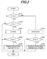
- the program begins at S10, in which it is determined whether the voltage V1 of the DC power bus 22 is equal to or less than a predetermined voltage a (e.g., 700 V).
- a predetermined voltage a e.g. 700 V.
- the voltage V1 is decreased when an amount of power consumed at the power destination exceeds that generated by the AC generator 12b and photovoltaic generator 14a. Therefore, when the result in S10 is affirmative, the program proceeds to S12, in which the storage unit 16 is controlled to discharge. Specifically, since the generated power is insufficient for the power demand, the voltage V1 is increased.
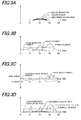
- FIG. 3A is a graph showing amounts of solar radiation, solar power generated by the photovoltaic generator 14a and heat (absorbed solar heat) absorbed by the solar heater 12i.
- FIG. 3B is a graph showing amounts of power (cogeneration power) generated by the AC generator 12b of the cogeneration unit 12, solar power and power consumed at the power destination (power demand).
- FIG. 3C is a graph showing amounts of charged/discharged power of the battery 16a and transmitted power (purchased power) from the commercial power unit 18.
- FIG. 3D is a graph showing amounts of exhausted heat (cogeneration exhausted heat) from the engine 12a of the cogeneration unit 12, absorbed solar heat, heat (electric heater heat) generated by the electric heater 121 and heat corresponding to hot water demand (thermal demand).
- the cogeneration unit 12 is to be operated for a long period of time.
- the operating time of the cogeneration unit 12 is calculated from a heat amount stored in the tank 12d (which is estimated based on the outputs of the thermometer 12m and water gauge 12n), a heat amount required on that day (which is estimated based on the operation setting data) and an absorbed heat amount expected for the solar heater 12i (which is estimated based on solar radiation data with respect to different weathers prepared beforehand).
- the voltage V2 of the battery 16a is decreased to or below the predetermined voltage ⁇ and power is purchased from the commercial power source 24.
- the battery 16a is in the charged condition during power purchase.
- the cogeneration unit 12 is operated only for a short period of time.
- the cogeneration unit 12 is started in the morning for supplying hot water, it is stopped after a short while. Even though the cogeneration unit 12 is stopped, since the amount of solar power is greater than the power demand, the voltage V1 becomes the predetermined voltage ⁇ or more and it makes the battery 16a to be in the charged condition.
- the electric heater 121 is operated so that the surplus electricity is converted to heat and stored in the tank 12d.
- the cogeneration unit 12 power generated by the photovoltaic generator 14a can be efficiently used to the utmost extent, without loss.
- the embodiment is configured to have a power supply system (10) having a cogeneration unit (12) equipped with an internal combustion engine (12a) and a generator (AC generator 12b) driven by the engine to generate power to be supplied to a power destination (load) and hot water to be supplied to a hot water destination (load) by heat exhausted from the engine, characterized by: a natural energy generation unit (14) that generates power with natural energy; a power supply unit (20) that receives the power generated by the generator (12b) and the natural energy generation unit (14) to supply the received power to the power destination; a connecting bus (DC power bus 22) that electrically connects the cogeneration unit, the natural energy generation unit and the power supply unit; a voltage detector (voltage sensor 22a) that detects voltage (V1) of the power flowing through the connecting bus; and an electric heater (121) that heats the hot water by the power supplied through the connecting bus, wherein the power supply unit (20) controls operation of the electric heater based on the detected connecting bus power voltage (S10 - S24).
- the electric heater (121) is operated to on to convert the surplus electricity to heat for increasing the temperature of water to be supplied. With this, it becomes possible to suppress the power transmission loss of the surplus electricity and utilize the surplus electricity more effectively than transmitting it back to the commercial power source 24.
- the surplus electricity is used to heat water to be supplied, it becomes possible to shorten the operating time of the cogeneration unit (12), thereby enabling to utilize the natural energy to the utmost extent, without loss.
- the power supply unit (20) controls the operation of the storage unit to discharge the stored power when the detected connecting bus power voltage (V1) is equal to or less than a predetermined voltage ( ⁇ ). More specifically, the system further includes: a storage unit (16) that is connected to the connecting bus and stores the power not supplied to the power destination; and a detector (16d) that detects voltage (V2) of the power stored in the storage unit, and the power supply unit (20) controls the operation of the electric heater (121) based on the detected stored power voltage (S10 - S24).
- the power supply unit (20) controls the operation of the electric heater (121) to on when the detected connecting bus power voltage (V1) exceeds a predetermined first voltage ( ⁇ ) and the detected stored power voltage (V2) exceeds a predetermined second voltage ( ⁇ ) (S10 - S24).
- the power supply unit (20) controls the operation of the electric heater (121) to on when the detected connecting bus power voltage (V1) exceeds a predetermined first voltage ( ⁇ ), but is equal to or less than a predetermined third voltage ( ⁇ ), and the detected stored power voltage (V2) exceeds a predetermined fourth voltage ( ⁇ ) (S10 - S24).
- the surplus electricity generation can be appropriately determined and hence, it becomes possible to effectively utilize the surplus electricity through the electric heater (121).
- the connecting bus (22) is connected to a commercial power source (24) and the power supply unit (22) determines whether or not to receive power from the commercial power source based on the detected connecting bus voltage (V1) and the detected stored power voltage (V2) (S10 - S16). More specifically, the power supply unit (22) determines to receive the power form the commercial power source when the detected connecting bus power voltage (V1) is equal to or less than a predetermined first voltage ( ⁇ ) and the detected stored power voltage (V2) is equal to or less than a predetermined second voltage ( ⁇ ).
- the natural energy generation unit (14) comprises a photovoltaic generator (14a). With this, since it is configured to generate power through sunlight, it becomes possible to achieve high energy efficiency compared to power generation using other kinds of natural energy.
- the cogeneration unit (12) has a solar heater (12i) that heats the water with solar heat. With this, it becomes possible to heat water to be supplied further using natural energy.
- the natural energy generation unit 14 is configured to be constituted as the photovoltaic generator 14a, it may instead be an aerogenerator or a geothermal generator. Alternatively, a plurality of number of the natural energy generation units may be connected to the DC power bus 22.
- the battery 16a is to be in the charged condition during power purchase, in order to keep cost low on power purchase, it is not necessarily to be in the charged condition.
Landscapes
- Engineering & Computer Science (AREA)
- Power Engineering (AREA)
- Physics & Mathematics (AREA)
- Life Sciences & Earth Sciences (AREA)
- Sustainable Development (AREA)
- Sustainable Energy (AREA)
- Thermal Sciences (AREA)
- Chemical & Material Sciences (AREA)
- Combustion & Propulsion (AREA)
- Mechanical Engineering (AREA)
- General Engineering & Computer Science (AREA)
- Supply And Distribution Of Alternating Current (AREA)
- Charge And Discharge Circuits For Batteries Or The Like (AREA)
- Secondary Cells (AREA)
- Heat-Pump Type And Storage Water Heaters (AREA)
- Direct Current Feeding And Distribution (AREA)
Applications Claiming Priority (1)
| Application Number | Priority Date | Filing Date | Title |
|---|---|---|---|
| JP2009185137A JP5465949B2 (ja) | 2009-08-07 | 2009-08-07 | 電力供給システム |
Publications (3)
| Publication Number | Publication Date |
|---|---|
| EP2284382A2 true EP2284382A2 (fr) | 2011-02-16 |
| EP2284382A3 EP2284382A3 (fr) | 2014-08-13 |
| EP2284382B1 EP2284382B1 (fr) | 2018-02-07 |
Family
ID=43127361
Family Applications (1)
| Application Number | Title | Priority Date | Filing Date |
|---|---|---|---|
| EP10172234.6A Not-in-force EP2284382B1 (fr) | 2009-08-07 | 2010-08-06 | Système d'alimentation |
Country Status (4)
| Country | Link |
|---|---|
| US (1) | US8180499B2 (fr) |
| EP (1) | EP2284382B1 (fr) |
| JP (1) | JP5465949B2 (fr) |
| CA (1) | CA2712205C (fr) |
Cited By (12)
| Publication number | Priority date | Publication date | Assignee | Title |
|---|---|---|---|---|
| WO2012136346A1 (fr) * | 2011-04-08 | 2012-10-11 | Franz Muschaweck | Dispositif de distribution d'énergie électrique pour un immeuble |
| ITTV20110052A1 (it) * | 2011-04-19 | 2012-10-20 | Bergamin Luca | Sistema ibrido monofase ed automatico con apparecchiatura dedicata per gestire l'energia prodotta da fonti rinnovabili |
| EP2590292A1 (fr) * | 2011-11-07 | 2013-05-08 | Belenos Clean Power Holding AG | Procede de gestion d'une installation de production et de stockage d'energie renouvelable |
| WO2013117956A3 (fr) * | 2012-02-08 | 2013-11-07 | Lako, Daniel | Équipement de commutation de puissance pour chaudières mises en œuvre dans des systèmes régulés de chauffage d'eau utilisant du courant continu issu de panneaux photovoltaïques |
| DE102012017631A1 (de) * | 2012-09-06 | 2014-03-06 | Stefan Finger | Verfahren und Vorrichtung zur Regelung von Netz gekoppelten Eigenverbrauchs-Netzen mit einspeise fähigen Wechselspannungs-Generatoren, ohne Netz-Einspeisung und ohne elektrische Energie-Speicher, sowie mit optionalen Insel- bzw. Notstrom-Betrieb |
| ITVA20120034A1 (it) * | 2012-10-03 | 2014-04-04 | Bytronic S R L | Sistema di condivisione energetica da diverse fonti in cui la rete pubblica ha funzione passiva o di ausilio o di emergenza |
| EP2719973A4 (fr) * | 2011-06-06 | 2014-07-02 | Panasonic Corp | Procédé de fonctionnement pour pompe à chaleur et système de pompe à chaleur |
| EP2719972A4 (fr) * | 2011-06-06 | 2014-07-02 | Panasonic Corp | Procédé de fonctionnement pour pompe à chaleur et système de pompe à chaleur |
| EP2719971A4 (fr) * | 2011-06-06 | 2014-07-02 | Panasonic Corp | Procédé de fonctionnement pour pompe à chaleur, et système de pompe à chaleur |
| DE102013100999A1 (de) * | 2013-01-31 | 2014-07-31 | Philipp Börner | Energieversorgungsanordnung und Verfahren zur schnellen Umschaltung von einem Netzparallelbetriebsmodus in einen Insel-betriebsmodus bei einer Energieversorgungsanordnung |
| WO2014118059A1 (fr) | 2013-01-30 | 2014-08-07 | Sma Solar Technology Ag | Procédé et onduleur pour distribuer la puissance par l'intermédiaire de plusieurs sources de courant continu connectées collectivement à une entrée de tension continue d'un convertisseur cc/ca |
| JP2015510098A (ja) * | 2012-02-08 | 2015-04-02 | ラコ,ダニエル | 水の加熱調節において光起電性パネルからの直流を利用する、ボイラーのための電力切替え装置 |
Families Citing this family (31)
| Publication number | Priority date | Publication date | Assignee | Title |
|---|---|---|---|---|
| US8746232B2 (en) * | 2009-08-07 | 2014-06-10 | Honda Motor Co., Ltd. | Hot water supply system |
| JP5539750B2 (ja) * | 2010-02-17 | 2014-07-02 | トヨタホーム株式会社 | 住宅用電力システム |
| US8812164B2 (en) * | 2010-10-12 | 2014-08-19 | Engineered Electric Company | Portable cogeneration system incorporating renewable energy sources |
| EP2479862A1 (fr) * | 2011-01-25 | 2012-07-25 | Thomson Licensing | Gestion de l'alimentation en énergie d'un réseau local de transport d'énergie |
| JP5966247B2 (ja) * | 2011-03-01 | 2016-08-10 | ソニー株式会社 | 電池パック、蓄電システム、電子機器、電動車両、電力システムおよび制御システム |
| JP5690681B2 (ja) * | 2011-07-21 | 2015-03-25 | 日立アプライアンス株式会社 | 電力制御装置 |
| US20130043723A1 (en) * | 2011-08-19 | 2013-02-21 | Robert Bosch Gmbh | Solar synchronized loads for photovoltaic systems |
| JP2013074689A (ja) * | 2011-09-27 | 2013-04-22 | Panasonic Corp | エネルギー管理システム、およびエネルギー管理装置 |
| CN102570622B (zh) * | 2011-12-30 | 2014-03-26 | 合肥同智机电控制技术股份有限公司 | 超级电容的均压装置 |
| JP5900016B2 (ja) * | 2012-02-28 | 2016-04-06 | 株式会社デンソー | 統合遠隔制御システム |
| US9715261B2 (en) * | 2012-02-29 | 2017-07-25 | Thomas Wilkins | Continuous dynamic balancing of generation and loads |
| JP5851342B2 (ja) * | 2012-05-21 | 2016-02-03 | 株式会社辰巳菱機 | ハイブリッド型太陽熱温水器システム |
| JP6057564B2 (ja) * | 2012-07-03 | 2017-01-11 | 大阪瓦斯株式会社 | 熱供給システム |
| US9563215B2 (en) | 2012-07-14 | 2017-02-07 | Causam Energy, Inc. | Method and apparatus for actively managing electric power supply for an electric power grid |
| US9312698B2 (en) * | 2012-12-19 | 2016-04-12 | Robert Bosch Gmbh | System and method for energy distribution |
| JP6009976B2 (ja) * | 2013-03-07 | 2016-10-19 | 株式会社東芝 | エネルギー管理システム、エネルギー管理方法、プログラムおよびサーバ |
| JP6094360B2 (ja) * | 2013-03-27 | 2017-03-15 | アイシン精機株式会社 | 発電システム |
| JP6268786B2 (ja) * | 2013-07-26 | 2018-01-31 | 住友電気工業株式会社 | パワーコンディショナ、パワーコンディショナシステムおよびパワーコンディショナの制御方法 |
| JP6329347B2 (ja) * | 2013-08-07 | 2018-05-23 | 大和ハウス工業株式会社 | 太陽エネルギー利用システム |
| US20160266176A1 (en) * | 2013-12-30 | 2016-09-15 | Telefonaktiebolaget L M Ericsson (Publ) | Range Determination for an Intermediate Bus Architecture Power Supply Controller |
| CN105281624B (zh) * | 2014-06-17 | 2021-04-06 | 松下知识产权经营株式会社 | 热动力发电装置和热动力发电系统 |
| JP2016046839A (ja) * | 2014-08-20 | 2016-04-04 | アイシン精機株式会社 | 系統連系システム |
| US10326277B2 (en) * | 2015-06-26 | 2019-06-18 | Enphase Energy, Inc. | Hierarchical control of a plurality of power subsystems and method of operating the same |
| US10230241B1 (en) * | 2015-09-30 | 2019-03-12 | The United States Of America, As Represented By The Secretary Of The Navy | Self-optimizing hybrid power system |
| US11597355B2 (en) | 2015-12-21 | 2023-03-07 | John Oskwarek | Method and apparatus for the melting of snow and ice from vehicle exteriors |
| CN105470982B (zh) * | 2015-12-25 | 2018-06-26 | 北京四方继保自动化股份有限公司 | 一种含介质储能的智能微电网发电功率控制系统及控制方法 |
| US20170288400A1 (en) * | 2016-03-29 | 2017-10-05 | Donald Williams | Energy process handling system, assembly, and apparatus, and method of using or assembling the same |
| FR3059199B1 (fr) * | 2016-11-24 | 2021-01-01 | Lancey Energy Storage | Appareil de chauffage de type radiateur electrique incluant un convertisseur de tension |
| US11196258B2 (en) * | 2018-08-03 | 2021-12-07 | Sacramento Municipal Utility District | Energy control and storage system for controlling power based on a load shape |
| EP4344044A3 (fr) * | 2019-08-28 | 2024-05-29 | Huawei Digital Power Technologies Co., Ltd. | Onduleur de système de production d'énergie photovoltaïque connecté au réseau, appareil de démarrage, procédé et système |
| US12542440B2 (en) * | 2023-04-12 | 2026-02-03 | DG Matrix, Inc. | Resilient on-site microgrid system |
Citations (1)
| Publication number | Priority date | Publication date | Assignee | Title |
|---|---|---|---|---|
| JP2003339118A (ja) | 2002-05-22 | 2003-11-28 | My Way Giken Kk | 分散電源システム |
Family Cites Families (14)
| Publication number | Priority date | Publication date | Assignee | Title |
|---|---|---|---|---|
| JPH08186927A (ja) * | 1994-12-31 | 1996-07-16 | Tokyo Gas Co Ltd | コージェネレーションシステム |
| JP3738929B2 (ja) * | 1997-07-28 | 2006-01-25 | 本田技研工業株式会社 | エネルギ供給システム |
| JP2000205044A (ja) * | 1999-01-19 | 2000-07-25 | Shigeaki Kimura | コ―ジェネレ―ション装置 |
| JP2001258160A (ja) * | 2000-03-09 | 2001-09-21 | Omron Corp | ハイブリッド型発電システム |
| JP2003032906A (ja) * | 2001-07-11 | 2003-01-31 | Osaka Gas Co Ltd | 電源装置 |
| JP2003229154A (ja) * | 2002-02-01 | 2003-08-15 | Mitsubishi Heavy Ind Ltd | 余剰電力制御システム、余剰電力制御方法及び電力供給システム |
| JP3825020B2 (ja) * | 2002-08-01 | 2006-09-20 | 株式会社アイ・ヒッツ研究所 | 分散給電システム |
| JP3726265B2 (ja) * | 2002-12-25 | 2005-12-14 | 中国電力株式会社 | 直流連系による家庭用分散型電源装置及びその制御方法 |
| JP2005278338A (ja) * | 2004-03-25 | 2005-10-06 | Osaka Gas Co Ltd | 電力供給システム |
| JP2008524972A (ja) * | 2004-12-16 | 2008-07-10 | アニー ラサンサ ミショル ペレラ | 機会発電を通した分散された発電のコスト削減 |
| JP2006296173A (ja) * | 2005-04-05 | 2006-10-26 | Shoji Ueda | 家庭用トータルエネルギーシステム |
| US7217896B1 (en) * | 2006-01-25 | 2007-05-15 | Honeywell International, Inc. | Staked printed circuit board terminals for switch cases |
| JP5231745B2 (ja) * | 2007-02-19 | 2013-07-10 | 本田技研工業株式会社 | コージェネレーション装置 |
| KR20100061453A (ko) * | 2007-07-25 | 2010-06-07 | 트루라이트 인크. | 하이브리드 전력의 생성 및 사용을 관리하는 장치, 시스템 및 방법 |
-
2009
- 2009-08-07 JP JP2009185137A patent/JP5465949B2/ja not_active Expired - Fee Related
-
2010
- 2010-07-21 US US12/840,555 patent/US8180499B2/en active Active
- 2010-08-05 CA CA2712205A patent/CA2712205C/fr not_active Expired - Fee Related
- 2010-08-06 EP EP10172234.6A patent/EP2284382B1/fr not_active Not-in-force
Patent Citations (1)
| Publication number | Priority date | Publication date | Assignee | Title |
|---|---|---|---|---|
| JP2003339118A (ja) | 2002-05-22 | 2003-11-28 | My Way Giken Kk | 分散電源システム |
Cited By (16)
| Publication number | Priority date | Publication date | Assignee | Title |
|---|---|---|---|---|
| WO2012136346A1 (fr) * | 2011-04-08 | 2012-10-11 | Franz Muschaweck | Dispositif de distribution d'énergie électrique pour un immeuble |
| ITTV20110052A1 (it) * | 2011-04-19 | 2012-10-20 | Bergamin Luca | Sistema ibrido monofase ed automatico con apparecchiatura dedicata per gestire l'energia prodotta da fonti rinnovabili |
| US9267719B2 (en) | 2011-06-06 | 2016-02-23 | Panasonic Intellectual Property Management Co., Ltd. | Heat pump operation method and heat pump system |
| EP2719971A4 (fr) * | 2011-06-06 | 2014-07-02 | Panasonic Corp | Procédé de fonctionnement pour pompe à chaleur, et système de pompe à chaleur |
| US9677784B2 (en) | 2011-06-06 | 2017-06-13 | Panasonic Intellectual Property Management Co., Ltd. | Heat pump operation method and heat pump system |
| US9494373B2 (en) | 2011-06-06 | 2016-11-15 | Panasonic Intellectual Property Management Co., Ltd. | Heat pump operation method and heat pump system |
| EP2719973A4 (fr) * | 2011-06-06 | 2014-07-02 | Panasonic Corp | Procédé de fonctionnement pour pompe à chaleur et système de pompe à chaleur |
| EP2719972A4 (fr) * | 2011-06-06 | 2014-07-02 | Panasonic Corp | Procédé de fonctionnement pour pompe à chaleur et système de pompe à chaleur |
| EP2590292A1 (fr) * | 2011-11-07 | 2013-05-08 | Belenos Clean Power Holding AG | Procede de gestion d'une installation de production et de stockage d'energie renouvelable |
| JP2015510098A (ja) * | 2012-02-08 | 2015-04-02 | ラコ,ダニエル | 水の加熱調節において光起電性パネルからの直流を利用する、ボイラーのための電力切替え装置 |
| WO2013117956A3 (fr) * | 2012-02-08 | 2013-11-07 | Lako, Daniel | Équipement de commutation de puissance pour chaudières mises en œuvre dans des systèmes régulés de chauffage d'eau utilisant du courant continu issu de panneaux photovoltaïques |
| EA026301B1 (ru) * | 2012-02-08 | 2017-03-31 | Даниэль Лако | Устройство коммутации питания для бойлеров, применяемое для регулированного нагрева воды с использованием постоянного тока от фотоэлектрических панелей |
| DE102012017631A1 (de) * | 2012-09-06 | 2014-03-06 | Stefan Finger | Verfahren und Vorrichtung zur Regelung von Netz gekoppelten Eigenverbrauchs-Netzen mit einspeise fähigen Wechselspannungs-Generatoren, ohne Netz-Einspeisung und ohne elektrische Energie-Speicher, sowie mit optionalen Insel- bzw. Notstrom-Betrieb |
| ITVA20120034A1 (it) * | 2012-10-03 | 2014-04-04 | Bytronic S R L | Sistema di condivisione energetica da diverse fonti in cui la rete pubblica ha funzione passiva o di ausilio o di emergenza |
| WO2014118059A1 (fr) | 2013-01-30 | 2014-08-07 | Sma Solar Technology Ag | Procédé et onduleur pour distribuer la puissance par l'intermédiaire de plusieurs sources de courant continu connectées collectivement à une entrée de tension continue d'un convertisseur cc/ca |
| DE102013100999A1 (de) * | 2013-01-31 | 2014-07-31 | Philipp Börner | Energieversorgungsanordnung und Verfahren zur schnellen Umschaltung von einem Netzparallelbetriebsmodus in einen Insel-betriebsmodus bei einer Energieversorgungsanordnung |
Also Published As
| Publication number | Publication date |
|---|---|
| JP5465949B2 (ja) | 2014-04-09 |
| EP2284382A3 (fr) | 2014-08-13 |
| CA2712205A1 (fr) | 2011-02-07 |
| US20110035070A1 (en) | 2011-02-10 |
| CA2712205C (fr) | 2014-04-22 |
| EP2284382B1 (fr) | 2018-02-07 |
| JP2011041380A (ja) | 2011-02-24 |
| US8180499B2 (en) | 2012-05-15 |
Similar Documents
| Publication | Publication Date | Title |
|---|---|---|
| EP2284382B1 (fr) | Système d'alimentation | |
| US9557068B2 (en) | Heat pump hot-water supply system | |
| CN108496288B (zh) | 家用能源设备及操作家用能源设备的操作方法 | |
| US10571135B2 (en) | Renewable energy hot water heater with heat pump | |
| US4510756A (en) | Cogeneration | |
| US20180233914A1 (en) | Control device, energy management device, system, and control method | |
| WO2014152893A2 (fr) | Système photovoltaïque (pv) de micro-réseau | |
| JP2003079054A (ja) | 蓄電池を備えた太陽光発電システム | |
| EP1398842A1 (fr) | Appareil de cogeneration, procede de cogeneration, programme et support de donnees associes | |
| GB2562532B (en) | Heat and power generation and storage system | |
| JP2004312798A (ja) | 分散エネルギーシステムおよびその制御方法 | |
| JP6694757B2 (ja) | 給湯システム | |
| JP2002281568A (ja) | コジェネレーションシステム | |
| KR102479198B1 (ko) | 태양광을 이용한 건물 에너지 공급 시스템 | |
| GB2577231A (en) | Power supply apparatus and method | |
| JP4630429B2 (ja) | 燃料電池付建物 | |
| KR102913052B1 (ko) | 건물용 연료전지의 경제성 기반 최적 운전 제어장치 및 방법 | |
| US20130322858A1 (en) | Power generation system | |
| JP5905226B2 (ja) | エネルギー管理システム、エネルギー管理装置及び電力管理方法 | |
| JP7797272B2 (ja) | 電源管理システム | |
| EP2193586B1 (fr) | Système servant à produire simultanément de l'énergie électrique et de l'énergie thermique | |
| RU65150U1 (ru) | Гелиоветродизельгенераторная установка для энергоснабжения | |
| WO2023285772A1 (fr) | Système électrique de chauffage et d'eau chaude doté de régulateur d'énergie et procédé d'actionnement de système électrique de chauffage et d'eau chaude | |
| WO2019025657A1 (fr) | Système local de production et de gestion énergétique et procédé de fonctionnement dudit système | |
| GB2585820A (en) | Electrical heating and battery management system |
Legal Events
| Date | Code | Title | Description |
|---|---|---|---|
| PUAI | Public reference made under article 153(3) epc to a published international application that has entered the european phase |
Free format text: ORIGINAL CODE: 0009012 |
|
| 17P | Request for examination filed |
Effective date: 20100831 |
|
| AK | Designated contracting states |
Kind code of ref document: A2 Designated state(s): AL AT BE BG CH CY CZ DE DK EE ES FI FR GB GR HR HU IE IS IT LI LT LU LV MC MK MT NL NO PL PT RO SE SI SK SM TR |
|
| AX | Request for extension of the european patent |
Extension state: BA ME RS |
|
| PUAL | Search report despatched |
Free format text: ORIGINAL CODE: 0009013 |
|
| AK | Designated contracting states |
Kind code of ref document: A3 Designated state(s): AL AT BE BG CH CY CZ DE DK EE ES FI FR GB GR HR HU IE IS IT LI LT LU LV MC MK MT NL NO PL PT RO SE SI SK SM TR |
|
| AX | Request for extension of the european patent |
Extension state: BA ME RS |
|
| RIC1 | Information provided on ipc code assigned before grant |
Ipc: H02J 3/38 20060101ALI20140710BHEP Ipc: H02J 3/32 20060101ALI20140710BHEP Ipc: F02G 5/04 20060101AFI20140710BHEP Ipc: H02J 3/14 20060101ALI20140710BHEP |
|
| RIC1 | Information provided on ipc code assigned before grant |
Ipc: H02J 3/32 20060101ALI20170724BHEP Ipc: H02J 3/14 20060101ALI20170724BHEP Ipc: F24J 2/00 20140101ALI20170724BHEP Ipc: F02G 5/04 20060101AFI20170724BHEP Ipc: H02J 3/38 20060101ALI20170724BHEP |
|
| GRAP | Despatch of communication of intention to grant a patent |
Free format text: ORIGINAL CODE: EPIDOSNIGR1 |
|
| STAA | Information on the status of an ep patent application or granted ep patent |
Free format text: STATUS: GRANT OF PATENT IS INTENDED |
|
| INTG | Intention to grant announced |
Effective date: 20171124 |
|
| RIN1 | Information on inventor provided before grant (corrected) |
Inventor name: KANAI, YASUSHI |
|
| GRAS | Grant fee paid |
Free format text: ORIGINAL CODE: EPIDOSNIGR3 |
|
| GRAA | (expected) grant |
Free format text: ORIGINAL CODE: 0009210 |
|
| STAA | Information on the status of an ep patent application or granted ep patent |
Free format text: STATUS: THE PATENT HAS BEEN GRANTED |
|
| AK | Designated contracting states |
Kind code of ref document: B1 Designated state(s): AL AT BE BG CH CY CZ DE DK EE ES FI FR GB GR HR HU IE IS IT LI LT LU LV MC MK MT NL NO PL PT RO SE SI SK SM TR |
|
| REG | Reference to a national code |
Ref country code: GB Ref legal event code: FG4D |
|
| REG | Reference to a national code |
Ref country code: AT Ref legal event code: REF Ref document number: 968916 Country of ref document: AT Kind code of ref document: T Effective date: 20180215 Ref country code: CH Ref legal event code: EP |
|
| REG | Reference to a national code |
Ref country code: NL Ref legal event code: FP Ref country code: IE Ref legal event code: FG4D |
|
| REG | Reference to a national code |
Ref country code: DE Ref legal event code: R096 Ref document number: 602010048389 Country of ref document: DE |
|
| REG | Reference to a national code |
Ref country code: AT Ref legal event code: MK05 Ref document number: 968916 Country of ref document: AT Kind code of ref document: T Effective date: 20180207 |
|
| PG25 | Lapsed in a contracting state [announced via postgrant information from national office to epo] |
Ref country code: ES Free format text: LAPSE BECAUSE OF FAILURE TO SUBMIT A TRANSLATION OF THE DESCRIPTION OR TO PAY THE FEE WITHIN THE PRESCRIBED TIME-LIMIT Effective date: 20180207 Ref country code: CY Free format text: LAPSE BECAUSE OF FAILURE TO SUBMIT A TRANSLATION OF THE DESCRIPTION OR TO PAY THE FEE WITHIN THE PRESCRIBED TIME-LIMIT Effective date: 20180207 Ref country code: FI Free format text: LAPSE BECAUSE OF FAILURE TO SUBMIT A TRANSLATION OF THE DESCRIPTION OR TO PAY THE FEE WITHIN THE PRESCRIBED TIME-LIMIT Effective date: 20180207 Ref country code: LT Free format text: LAPSE BECAUSE OF FAILURE TO SUBMIT A TRANSLATION OF THE DESCRIPTION OR TO PAY THE FEE WITHIN THE PRESCRIBED TIME-LIMIT Effective date: 20180207 Ref country code: HR Free format text: LAPSE BECAUSE OF FAILURE TO SUBMIT A TRANSLATION OF THE DESCRIPTION OR TO PAY THE FEE WITHIN THE PRESCRIBED TIME-LIMIT Effective date: 20180207 Ref country code: NO Free format text: LAPSE BECAUSE OF FAILURE TO SUBMIT A TRANSLATION OF THE DESCRIPTION OR TO PAY THE FEE WITHIN THE PRESCRIBED TIME-LIMIT Effective date: 20180507 |
|
| PG25 | Lapsed in a contracting state [announced via postgrant information from national office to epo] |
Ref country code: IS Free format text: LAPSE BECAUSE OF FAILURE TO SUBMIT A TRANSLATION OF THE DESCRIPTION OR TO PAY THE FEE WITHIN THE PRESCRIBED TIME-LIMIT Effective date: 20180607 Ref country code: BG Free format text: LAPSE BECAUSE OF FAILURE TO SUBMIT A TRANSLATION OF THE DESCRIPTION OR TO PAY THE FEE WITHIN THE PRESCRIBED TIME-LIMIT Effective date: 20180507 Ref country code: AT Free format text: LAPSE BECAUSE OF FAILURE TO SUBMIT A TRANSLATION OF THE DESCRIPTION OR TO PAY THE FEE WITHIN THE PRESCRIBED TIME-LIMIT Effective date: 20180207 Ref country code: PL Free format text: LAPSE BECAUSE OF FAILURE TO SUBMIT A TRANSLATION OF THE DESCRIPTION OR TO PAY THE FEE WITHIN THE PRESCRIBED TIME-LIMIT Effective date: 20180207 Ref country code: LV Free format text: LAPSE BECAUSE OF FAILURE TO SUBMIT A TRANSLATION OF THE DESCRIPTION OR TO PAY THE FEE WITHIN THE PRESCRIBED TIME-LIMIT Effective date: 20180207 Ref country code: SE Free format text: LAPSE BECAUSE OF FAILURE TO SUBMIT A TRANSLATION OF THE DESCRIPTION OR TO PAY THE FEE WITHIN THE PRESCRIBED TIME-LIMIT Effective date: 20180207 Ref country code: GR Free format text: LAPSE BECAUSE OF FAILURE TO SUBMIT A TRANSLATION OF THE DESCRIPTION OR TO PAY THE FEE WITHIN THE PRESCRIBED TIME-LIMIT Effective date: 20180508 |
|
| PG25 | Lapsed in a contracting state [announced via postgrant information from national office to epo] |
Ref country code: RO Free format text: LAPSE BECAUSE OF FAILURE TO SUBMIT A TRANSLATION OF THE DESCRIPTION OR TO PAY THE FEE WITHIN THE PRESCRIBED TIME-LIMIT Effective date: 20180207 Ref country code: IT Free format text: LAPSE BECAUSE OF FAILURE TO SUBMIT A TRANSLATION OF THE DESCRIPTION OR TO PAY THE FEE WITHIN THE PRESCRIBED TIME-LIMIT Effective date: 20180207 Ref country code: AL Free format text: LAPSE BECAUSE OF FAILURE TO SUBMIT A TRANSLATION OF THE DESCRIPTION OR TO PAY THE FEE WITHIN THE PRESCRIBED TIME-LIMIT Effective date: 20180207 Ref country code: EE Free format text: LAPSE BECAUSE OF FAILURE TO SUBMIT A TRANSLATION OF THE DESCRIPTION OR TO PAY THE FEE WITHIN THE PRESCRIBED TIME-LIMIT Effective date: 20180207 |
|
| REG | Reference to a national code |
Ref country code: DE Ref legal event code: R097 Ref document number: 602010048389 Country of ref document: DE |
|
| PG25 | Lapsed in a contracting state [announced via postgrant information from national office to epo] |
Ref country code: SM Free format text: LAPSE BECAUSE OF FAILURE TO SUBMIT A TRANSLATION OF THE DESCRIPTION OR TO PAY THE FEE WITHIN THE PRESCRIBED TIME-LIMIT Effective date: 20180207 Ref country code: DK Free format text: LAPSE BECAUSE OF FAILURE TO SUBMIT A TRANSLATION OF THE DESCRIPTION OR TO PAY THE FEE WITHIN THE PRESCRIBED TIME-LIMIT Effective date: 20180207 Ref country code: SK Free format text: LAPSE BECAUSE OF FAILURE TO SUBMIT A TRANSLATION OF THE DESCRIPTION OR TO PAY THE FEE WITHIN THE PRESCRIBED TIME-LIMIT Effective date: 20180207 Ref country code: CZ Free format text: LAPSE BECAUSE OF FAILURE TO SUBMIT A TRANSLATION OF THE DESCRIPTION OR TO PAY THE FEE WITHIN THE PRESCRIBED TIME-LIMIT Effective date: 20180207 |
|
| PLBE | No opposition filed within time limit |
Free format text: ORIGINAL CODE: 0009261 |
|
| STAA | Information on the status of an ep patent application or granted ep patent |
Free format text: STATUS: NO OPPOSITION FILED WITHIN TIME LIMIT |
|
| RIC2 | Information provided on ipc code assigned after grant |
Ipc: F24J 2/00 20181130ALI20170724BHEP Ipc: H02J 3/32 20060101ALI20170724BHEP Ipc: F02G 5/04 20060101AFI20170724BHEP Ipc: H02J 3/14 20060101ALI20170724BHEP Ipc: H02J 3/38 20060101ALI20170724BHEP |
|
| REG | Reference to a national code |
Ref country code: CH Ref legal event code: PK Free format text: BERICHTIGUNGEN |
|
| 26N | No opposition filed |
Effective date: 20181108 |
|
| REG | Reference to a national code |
Ref country code: CH Ref legal event code: PK Free format text: BERICHTIGUNGEN |
|
| RIC2 | Information provided on ipc code assigned after grant |
Ipc: F02G 5/04 20060101AFI20170724BHEP Ipc: H02J 3/14 20060101ALI20170724BHEP Ipc: F24J 2/00 20140101ALI20170724BHEP Ipc: H02J 3/38 20060101ALI20170724BHEP Ipc: H02J 3/32 20060101ALI20170724BHEP |
|
| PG25 | Lapsed in a contracting state [announced via postgrant information from national office to epo] |
Ref country code: SI Free format text: LAPSE BECAUSE OF FAILURE TO SUBMIT A TRANSLATION OF THE DESCRIPTION OR TO PAY THE FEE WITHIN THE PRESCRIBED TIME-LIMIT Effective date: 20180207 |
|
| PG25 | Lapsed in a contracting state [announced via postgrant information from national office to epo] |
Ref country code: MC Free format text: LAPSE BECAUSE OF FAILURE TO SUBMIT A TRANSLATION OF THE DESCRIPTION OR TO PAY THE FEE WITHIN THE PRESCRIBED TIME-LIMIT Effective date: 20180207 |
|
| REG | Reference to a national code |
Ref country code: CH Ref legal event code: PL |
|
| PG25 | Lapsed in a contracting state [announced via postgrant information from national office to epo] |
Ref country code: CH Free format text: LAPSE BECAUSE OF NON-PAYMENT OF DUE FEES Effective date: 20180831 Ref country code: LI Free format text: LAPSE BECAUSE OF NON-PAYMENT OF DUE FEES Effective date: 20180831 Ref country code: LU Free format text: LAPSE BECAUSE OF NON-PAYMENT OF DUE FEES Effective date: 20180806 |
|
| REG | Reference to a national code |
Ref country code: BE Ref legal event code: MM Effective date: 20180831 |
|
| REG | Reference to a national code |
Ref country code: IE Ref legal event code: MM4A |
|
| PG25 | Lapsed in a contracting state [announced via postgrant information from national office to epo] |
Ref country code: IE Free format text: LAPSE BECAUSE OF NON-PAYMENT OF DUE FEES Effective date: 20180806 |
|
| PG25 | Lapsed in a contracting state [announced via postgrant information from national office to epo] |
Ref country code: FR Free format text: LAPSE BECAUSE OF NON-PAYMENT OF DUE FEES Effective date: 20180831 Ref country code: BE Free format text: LAPSE BECAUSE OF NON-PAYMENT OF DUE FEES Effective date: 20180831 |
|
| REG | Reference to a national code |
Ref country code: DE Ref legal event code: R084 Ref document number: 602010048389 Country of ref document: DE |
|
| REG | Reference to a national code |
Ref country code: GB Ref legal event code: 746 Effective date: 20191219 |
|
| PG25 | Lapsed in a contracting state [announced via postgrant information from national office to epo] |
Ref country code: MT Free format text: LAPSE BECAUSE OF NON-PAYMENT OF DUE FEES Effective date: 20180806 |
|
| PG25 | Lapsed in a contracting state [announced via postgrant information from national office to epo] |
Ref country code: TR Free format text: LAPSE BECAUSE OF FAILURE TO SUBMIT A TRANSLATION OF THE DESCRIPTION OR TO PAY THE FEE WITHIN THE PRESCRIBED TIME-LIMIT Effective date: 20180207 |
|
| PG25 | Lapsed in a contracting state [announced via postgrant information from national office to epo] |
Ref country code: PT Free format text: LAPSE BECAUSE OF FAILURE TO SUBMIT A TRANSLATION OF THE DESCRIPTION OR TO PAY THE FEE WITHIN THE PRESCRIBED TIME-LIMIT Effective date: 20180207 Ref country code: HU Free format text: LAPSE BECAUSE OF FAILURE TO SUBMIT A TRANSLATION OF THE DESCRIPTION OR TO PAY THE FEE WITHIN THE PRESCRIBED TIME-LIMIT; INVALID AB INITIO Effective date: 20100806 |
|
| PG25 | Lapsed in a contracting state [announced via postgrant information from national office to epo] |
Ref country code: MK Free format text: LAPSE BECAUSE OF NON-PAYMENT OF DUE FEES Effective date: 20180207 |
|
| PGFP | Annual fee paid to national office [announced via postgrant information from national office to epo] |
Ref country code: NL Payment date: 20200824 Year of fee payment: 11 |
|
| PGFP | Annual fee paid to national office [announced via postgrant information from national office to epo] |
Ref country code: GB Payment date: 20200729 Year of fee payment: 11 Ref country code: DE Payment date: 20200722 Year of fee payment: 11 |
|
| REG | Reference to a national code |
Ref country code: DE Ref legal event code: R082 Ref document number: 602010048389 Country of ref document: DE Representative=s name: HL KEMPNER PATENTANWALT, RECHTSANWALT, SOLICIT, DE |
|
| REG | Reference to a national code |
Ref country code: DE Ref legal event code: R119 Ref document number: 602010048389 Country of ref document: DE |
|
| REG | Reference to a national code |
Ref country code: NL Ref legal event code: MM Effective date: 20210901 |
|
| GBPC | Gb: european patent ceased through non-payment of renewal fee |
Effective date: 20210806 |
|
| PG25 | Lapsed in a contracting state [announced via postgrant information from national office to epo] |
Ref country code: NL Free format text: LAPSE BECAUSE OF NON-PAYMENT OF DUE FEES Effective date: 20210901 |
|
| PG25 | Lapsed in a contracting state [announced via postgrant information from national office to epo] |
Ref country code: GB Free format text: LAPSE BECAUSE OF NON-PAYMENT OF DUE FEES Effective date: 20210806 Ref country code: DE Free format text: LAPSE BECAUSE OF NON-PAYMENT OF DUE FEES Effective date: 20220301 |