EP2284552A2 - Procédé d'inspection de la condition d'un moteur et dispositif d'inspection des caractéristiques du moteur - Google Patents
Procédé d'inspection de la condition d'un moteur et dispositif d'inspection des caractéristiques du moteur Download PDFInfo
- Publication number
- EP2284552A2 EP2284552A2 EP10171035A EP10171035A EP2284552A2 EP 2284552 A2 EP2284552 A2 EP 2284552A2 EP 10171035 A EP10171035 A EP 10171035A EP 10171035 A EP10171035 A EP 10171035A EP 2284552 A2 EP2284552 A2 EP 2284552A2
- Authority
- EP
- European Patent Office
- Prior art keywords
- motor
- counter electromotive
- electromotive force
- inspecting
- mover
- Prior art date
- Legal status (The legal status is an assumption and is not a legal conclusion. Google has not performed a legal analysis and makes no representation as to the accuracy of the status listed.)
- Granted
Links
- 238000000034 method Methods 0.000 title claims abstract description 14
- 238000004804 winding Methods 0.000 claims abstract description 6
- 238000009434 installation Methods 0.000 claims description 22
- MROJXXOCABQVEF-UHFFFAOYSA-N Actarit Chemical compound CC(=O)NC1=CC=C(CC(O)=O)C=C1 MROJXXOCABQVEF-UHFFFAOYSA-N 0.000 claims 7
- 238000007689 inspection Methods 0.000 abstract description 10
- 238000005259 measurement Methods 0.000 description 3
- 230000002159 abnormal effect Effects 0.000 description 2
- 238000010586 diagram Methods 0.000 description 2
- 238000001514 detection method Methods 0.000 description 1
- 238000012986 modification Methods 0.000 description 1
- 230000004048 modification Effects 0.000 description 1
- 238000010248 power generation Methods 0.000 description 1
Images


Classifications
-
- G—PHYSICS
- G01—MEASURING; TESTING
- G01R—MEASURING ELECTRIC VARIABLES; MEASURING MAGNETIC VARIABLES
- G01R31/00—Arrangements for testing electric properties; Arrangements for locating electric faults; Arrangements for electrical testing characterised by what is being tested not provided for elsewhere
- G01R31/34—Testing dynamo-electric machines
- G01R31/343—Testing dynamo-electric machines in operation
Definitions
- the present invention relates to a method of inspecting a condition of a motor that generates a counter electromotive force or counter electromotive voltage when a mover of the motor is moved by an external force, and to a device for inspecting motor characteristics.
- JP 2002-131153 discloses a torque measuring device for measuring a torque without using a torque meter.
- Japanese Patent Application Publication No. 61-124256 discloses a method of measuring a thrust generated by a voice-coil linear motor by applying an external force for reciprocating a coil of the linear motor to calculate a thrust constant.
- the installation condition of a mover and a stator affects an output of the motor.
- a gap gauge is inserted into a gap formed between the mover and the stator to measure mechanical dimensions in order to inspect the installation condition.
- inspection is performed with the motor removed from the apparatus, and thus a mechanical error may likely occur when the motor is reinstalled in the apparatus after the inspection.
- An object of the present invention is to provide a method of inspecting motor conditions and a device for inspecting motor characteristics allowing inspection of a motor installed in an apparatus without removing the motor from the apparatus.
- Another object of the present invention is to provide a method of inspecting motor conditions and a device for inspecting motor characteristics allowing inspection as to whether or not a motor is properly installed in a convenient way.
- the present invention is directed to a method of inspecting motor conditions and a device for inspecting motor characteristics allowing inspection of a condition of a motor installed in an apparatus without removing the motor from the apparatus.
- a device for inspecting motor characteristics includes: a measuring section for measuring a frequency value and an amplitude value of a waveform of a counter electromotive force generated when a mover of the motor is moved by an external force; a computing section for computing a counter electromotive force constant on the basis of the frequency value and the amplitude value; and a result display section for displaying a predetermined indication for a computed result or an expected computed result of the counter electromotive force constant. Then, an armature winding of the motor installed in the apparatus and the device for inspecting motor characteristics are electrically connected with a power supply line disconnected from the motor.
- a motor has a power generation function.
- a counter electromotive force or counter electromotive voltage is generated across terminals of the motor.
- a counter electromotive force constant Ke ⁇ which is one of constants indicating characteristics of the motor, is computed to determine whether or not the characteristics of the motor are proper.
- the counter electromotive force constant Ke ⁇ can be calculated by measuring the peak and frequency values of the counter electromotive voltage. Accordingly, since the device for inspecting motor characteristics according to the present invention is intended to inspect a motor installed in an apparatus, an external force is applied, for example manually, to the mover of the motor when the motor is not driven and then is forcibly driven to generate a counter electromotive force.
- the counter electromotive force thus generated is represented by a waveform whose frequency is also not constant.
- a zero crossing detecting circuit is utilized to measure the frequency by determining a period from a point at which the counter electromotive force waveform crosses a zero point to a point at which the counter electromotive force waveform crosses a next zero point as one cycle.
- the counter electromotive force constant Ke ⁇ is calculated using an amplitude value of the waveform of which the frequency has been measured (a peak value of the counter electromotive voltage).
- the result display section displays the computed result (a numerical value) for the counter electromotive force constant, which allows a measurer (a person who performs measurements) to determine whether or not the obtained counter electromotive force constant is proper for the motor. If the obtained counter electromotive force constant is not proper, it is found that the motor is in an abnormal state.
- the result display section may display a predetermined indication for an expected computed result of the counter electromotive force constant. This configuration facilitates determination as to whether or not the characteristics of the motor are proper even if it is not readily determined based on the counter electromotive force constant of the motor.
- any motor that generates a counter electromotive force may be inspected.
- any type of motor such as a DC motor, a linear motor, a servo motor, and a stepping motor may be inspected.
- the motor to be inspected is a linear motor including a stator fixed to a stationary portion of an apparatus and a mover provided in a movable portion of the apparatus
- the device for inspecting motor characteristics may further include an installation condition determining section for determining a size of a gap between a magnetic pole provided in the stator and a magnetic pole provided in the mover on the basis of the computed result to determine whether or not the motor is properly installed on the basis of the determined gap size. Because the gap size and the counter electromotive force constant are inversely proportional to each other, it is possible to know the gap size in the linear motor in the installed state utilizing such inversely proportional relationship, which allows determination as to the installation condition of the motor.
- stator and the mover of a linear motor are separately formed, and assembled together at the location of use. That is, motor installation and gap adjustment is often performed by a user. Therefore, gap adjustment may not be adequately performed using a gap gauge, as a result of which a sufficient output of the linear motor may not be obtained. By using the device for inspecting motor characteristics according to the present invention, gap adjustment may be easily performed.
- the installation condition determining section for a linear motor determines that the gap size exceeds an appropriate range if the counter electromotive force constant falls below a predetermined threshold range and that the gap size falls below the appropriate range if the counter electromotive force constant exceeds the predetermined threshold range, and then the installation condition determining section determines that the motor is not properly installed in either case.
- This configuration further facilitates gap adjustment.
- Fig. 1 shows an exemplary embodiment of a device for inspecting motor characteristics according to the present invention.
- Fig. 2 is a block diagram showing the configuration of the embodiment of the present invention.
- a device for inspecting motor characteristics 1 is connected to a linear motor 3 to be inspected.
- the linear motor 3 includes a stator 3a fixed to a stationary portion of an apparatus and a mover 3b provided in a movable portion of the apparatus.
- the device for inspecting motor characteristics 1 is connected via a cable 7 to a power supply line 5 connected to a motor winding of the mover 3b of the linear motor 3 from which a power supply line has been disconnected.
- a signal receiving section 9 of the device for inspecting motor characteristics 1 receives a waveform of a counter electromotive force generated when the mover 3b of the linear motor 3 is moved by an external force.
- a measuring section 11 includes a zero crossing detecting circuit 13 and a frequency detecting circuit 15 for detecting a frequency of a voltage of the counter electromotive force, and further includes a peak value detecting circuit 17 for detecting a peak value of the voltage of the counter electromotive force.
- a computing section 19 computes a counter electromotive force constant on the basis of the frequency value and the voltage peak value detected by the measuring section 11 and then causes an indication for a computed result of the counter electromotive force constant to be displayed on a result display section 21.
- a storage section 23 stores a table for determining an installation condition of the linear motor 3, and an installation condition determining section 25 causes an indication for the determined installation condition on the basis of the computed result to be displayed on the result display section 21.
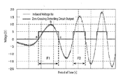
- the signal receiving section 9 receives a waveform of a counter electromotive force generated by the linear motor 3 as shown in Fig. 4 , and sends a signal to the measuring section 11.
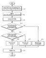
- the measuring section 11 measures a frequency value and a voltage peak value (in step ST1).
- the frequency value is determined as follows.
- the motor When the mover of the motor is moved by an external force, the motor generates a counter electromotive force whose frequency and voltage peak values are not constant as shown in Fig. 4 .
- the zero crossing detecting circuit 13 outputs a voltage whose value changes from 0 V to 5 V and from 5 V to 0 V at points where the counter electromotive force waveform crosses the value of zero (zero crossing points).
- the zero crossing detecting circuit 13 outputs a-waveform of a zero crossing detection circuit output Vo of Pig. 4.
- points a and c of the beginning waveform represent zero crossing points
- the peak value detecting circuit 17 detects a point b as a peak value of the waveform.
- the formula (1) is derived as follows.
- N 120 ⁇ f / P where f is the frequency value of the counter electromotive voltage in units of Hz, and P is the number of poles.
- the counter electromotive force constant Ke ⁇ can be derived through multiplication of the constant C if the counter electromotive voltage peak value Ke in units of V and the counter electromotive voltage frequency value f in units of Hz are measured.
- the counter electromotive force constant Ke ⁇ can be computed using the formula (1) irrespective of the type of the motor, and can be calculated from the counter electromotive force waveform of Fig. 4 discussed earlier. While the constant C has been provided in advance in the computing section 19 in the embodiment, it is a matter of course that the constant C may be overwritten by an external device or an input section provided in the device of inspecting motor characteristics 1 for the purpose of generality.
- the installation condition determining section 25 may determine the installation condition of the linear motor 3.
- the storage section 23 stores a table defining a size of a gap between a magnetic pole provided in the stator and a magnetic pole provided in the mover, and the computed counter electromotive force constant Ke ⁇ is compared with the table (in step ST3). It is determined whether or not the counter electromotive force constant Ke ⁇ falls within a certain threshold range (in step ST4). If the counter electromotive force constant Ke ⁇ falls within the threshold range, it is determined that the gap size falls within an appropriate range (in step ST5). If the counter electromotive force constant Ke ⁇ does not fall within the threshold range, it is determined whether or not the counter electromotive force constant Ke ⁇ exceeds the threshold range (in step ST6).
- step ST7 If the counter electromotive force constant Ke ⁇ exceeds the threshold range, it is determined that the gap size falls below the appropriate range (in step ST7). If the counter electromotive force constant Ke ⁇ falls below the threshold range, it is determined that the gap size exceeds the appropriate range (in step ST8). Finally, the result display section 21 displays an indication for the computed result including the counter electromotive force constant (in step ST9).
- the installation condition determining section 25 is provided to determine whether or not the gap size is proper in the embodiment, it is not necessary to provide the installation condition determining section 25 if it is only necessary to obtain the counter electromotive force constant Ke ⁇ . If a motor other than a linear motor is to be inspected, it is not necessary to make a determination as to a gap size. In this case, a general determining section may be provided in place of the installation condition determining section 25 so that the result display section 21 displays an indication that the motor is in a normal condition if the counter electromotive force constant Ke ⁇ falls within the threshold range, and displays an indication that the motor is in an abnormal condition if the counter electromotive force constant Ke ⁇ does not fall within the threshold range.
- characteristics of a motor may be inspected on the basis of a counter electromotive force waveform.
- the characteristics of the motor may be inspected without removing the motor from an apparatus and without the need for a tachometer or a speed sensor.
Landscapes
- Physics & Mathematics (AREA)
- General Physics & Mathematics (AREA)
- Tests Of Circuit Breakers, Generators, And Electric Motors (AREA)
- Control Of Linear Motors (AREA)
Applications Claiming Priority (1)
| Application Number | Priority Date | Filing Date | Title |
|---|---|---|---|
| JP2009177091A JP4988796B2 (ja) | 2009-07-29 | 2009-07-29 | モータの状況検査方法 |
Publications (3)
| Publication Number | Publication Date |
|---|---|
| EP2284552A2 true EP2284552A2 (fr) | 2011-02-16 |
| EP2284552A3 EP2284552A3 (fr) | 2011-08-03 |
| EP2284552B1 EP2284552B1 (fr) | 2012-10-10 |
Family
ID=42983362
Family Applications (1)
| Application Number | Title | Priority Date | Filing Date |
|---|---|---|---|
| EP10171035A Not-in-force EP2284552B1 (fr) | 2009-07-29 | 2010-07-28 | Procédé d'inspection de la condition d'un moteur linéaire |
Country Status (5)
| Country | Link |
|---|---|
| US (1) | US20110029271A1 (fr) |
| EP (1) | EP2284552B1 (fr) |
| JP (1) | JP4988796B2 (fr) |
| KR (1) | KR20110013254A (fr) |
| CN (1) | CN101988951B (fr) |
Cited By (1)
| Publication number | Priority date | Publication date | Assignee | Title |
|---|---|---|---|---|
| CN109001629A (zh) * | 2018-07-05 | 2018-12-14 | 青岛艾普智能仪器有限公司 | 一种电机的反电动势测试方法 |
Families Citing this family (11)
| Publication number | Priority date | Publication date | Assignee | Title |
|---|---|---|---|---|
| JP5656671B2 (ja) * | 2011-01-27 | 2015-01-21 | 山洋電気株式会社 | モータの状況検査方法及びモータ特性検査装置 |
| RU2529596C1 (ru) * | 2013-03-11 | 2014-09-27 | Федеральное государственное бюджетное образовательное учреждение высшего профессионального образования "Забайкальский государственный университет" (ФГБОУ ВПО "ЗабГУ") | Способ диагностики межвитковых замыканий асинхронного электродвигателя |
| CN105137351A (zh) * | 2015-07-27 | 2015-12-09 | 深圳市安进汽车电子有限公司 | 测量仪表步进电机输出平稳性的方法 |
| CN106291058A (zh) * | 2016-08-15 | 2017-01-04 | 珠海凌达压缩机有限公司 | 一种电机的反电动势测量装置及方法 |
| JP6870555B2 (ja) * | 2017-09-29 | 2021-05-12 | ブラザー工業株式会社 | 監視装置 |
| CN110320417A (zh) * | 2018-03-30 | 2019-10-11 | 青岛海尔智能技术研发有限公司 | 一种生成线性压缩机的功率值和频率值的方法和装置 |
| CN111022307A (zh) * | 2019-12-16 | 2020-04-17 | 珠海格力节能环保制冷技术研究中心有限公司 | 压缩机的控制方法、压缩机控制器及空调机组 |
| CN114295404B (zh) * | 2021-12-30 | 2024-05-14 | 长沙一派直驱科技股份有限公司 | 一种直线电机性能测试方法 |
| CN116430224B (zh) * | 2023-04-17 | 2026-02-03 | 武汉市聚芯微电子有限责任公司 | 一种马达驱动方式的校准方法及装置 |
| CN116500336A (zh) * | 2023-05-25 | 2023-07-28 | 新光维医疗科技(苏州)股份有限公司 | 电机往复频率测量装置和电机测试系统 |
| CN116559660B (zh) * | 2023-06-06 | 2024-10-01 | 浙江伟康电机有限公司 | 一种永磁同步电机轴向预紧力与反电势测试一体式设备 |
Citations (2)
| Publication number | Priority date | Publication date | Assignee | Title |
|---|---|---|---|---|
| JPS61124256A (ja) | 1984-11-21 | 1986-06-12 | Showa Electric Wire & Cable Co Ltd | ボイスコイル型リニアモ−タの動的推力測定法 |
| JP2002131153A (ja) | 2000-10-26 | 2002-05-09 | Yokogawa Electric Corp | トルク測定装置 |
Family Cites Families (6)
| Publication number | Priority date | Publication date | Assignee | Title |
|---|---|---|---|---|
| US6208497B1 (en) * | 1997-06-26 | 2001-03-27 | Venture Scientifics, Llc | System and method for servo control of nonlinear electromagnetic actuators |
| US6686761B2 (en) * | 2000-06-27 | 2004-02-03 | Industrial Technology Research Institute | Method for determining whether a rotor is good in magnetic induction by measuring the EMF of a motor |
| JP2002267727A (ja) * | 2001-03-09 | 2002-09-18 | Meidensha Corp | Pmモータの特性試験装置と方法 |
| JP4561019B2 (ja) * | 2001-09-05 | 2010-10-13 | 株式会社デンソー | 巻線異常検査方法 |
| US7340968B2 (en) * | 2002-05-21 | 2008-03-11 | Thermo Fisher Scientific (Asheville) Llc | Back EMF measurement to overcome the effects of motor temperature change |
| CN101383575A (zh) * | 2007-09-05 | 2009-03-11 | 晶致半导体股份有限公司 | 步进电机停转状态的判断装置及判断方法 |
-
2009
- 2009-07-29 JP JP2009177091A patent/JP4988796B2/ja not_active Expired - Fee Related
-
2010
- 2010-07-23 KR KR1020100071463A patent/KR20110013254A/ko not_active Withdrawn
- 2010-07-27 CN CN201010239619.XA patent/CN101988951B/zh not_active Expired - Fee Related
- 2010-07-28 EP EP10171035A patent/EP2284552B1/fr not_active Not-in-force
- 2010-07-28 US US12/845,259 patent/US20110029271A1/en not_active Abandoned
Patent Citations (2)
| Publication number | Priority date | Publication date | Assignee | Title |
|---|---|---|---|---|
| JPS61124256A (ja) | 1984-11-21 | 1986-06-12 | Showa Electric Wire & Cable Co Ltd | ボイスコイル型リニアモ−タの動的推力測定法 |
| JP2002131153A (ja) | 2000-10-26 | 2002-05-09 | Yokogawa Electric Corp | トルク測定装置 |
Cited By (1)
| Publication number | Priority date | Publication date | Assignee | Title |
|---|---|---|---|---|
| CN109001629A (zh) * | 2018-07-05 | 2018-12-14 | 青岛艾普智能仪器有限公司 | 一种电机的反电动势测试方法 |
Also Published As
| Publication number | Publication date |
|---|---|
| EP2284552A3 (fr) | 2011-08-03 |
| JP2011033356A (ja) | 2011-02-17 |
| JP4988796B2 (ja) | 2012-08-01 |
| EP2284552B1 (fr) | 2012-10-10 |
| US20110029271A1 (en) | 2011-02-03 |
| CN101988951A (zh) | 2011-03-23 |
| CN101988951B (zh) | 2014-11-26 |
| KR20110013254A (ko) | 2011-02-09 |
Similar Documents
| Publication | Publication Date | Title |
|---|---|---|
| EP2284552B1 (fr) | Procédé d'inspection de la condition d'un moteur linéaire | |
| KR101474187B1 (ko) | 소자의 모니터링 방법 | |
| US10310016B2 (en) | Method for the diagnostics of electromechanical system based on impedance analysis | |
| JP5546545B2 (ja) | 電気機械のロータの動作中に電気機械を監視および/または分析する方法および電気機械を動作中に監視および/または分析する装置 | |
| EP3306284A1 (fr) | Procédé et système pour déterminer l'état d'une machine électrique | |
| EP3143418B1 (fr) | Procédé et système de détection de défaillance de rotor | |
| KR101633972B1 (ko) | 비틀림 진동의 진단 및 평가 장치와 그 방법 | |
| EP2482091B1 (fr) | Procédé d'inspection de la condition de moteur et dispositif d'inspection de caractéristiques de moteur | |
| US20160216333A1 (en) | System and method for induction motor rotor bar magnetic field analysis | |
| KR20100130326A (ko) | 전자식 모터 부하시험장치 | |
| CN104315968A (zh) | 监测直驱风力发电机气隙变化的方法和装置 | |
| US9599452B2 (en) | Non-contact electrical machine air gap measurement tool | |
| CN109962648B (zh) | 一种电机零位检测方法和系统 | |
| KR101680242B1 (ko) | 영구자석 동기 전동기 진단 시스템, 방법, 및 상기 방법을 실행시키기 위한 컴퓨터 판독 가능한 프로그램을 기록한 기록 매체 | |
| JP2000137053A (ja) | オンライン絶縁劣化診断方法及び装置 | |
| CN105527572A (zh) | 一种有刷电动机的检测系统和方法 | |
| CN115047209A (zh) | 一种转速传感器检测精度自适应调试方法及装置 | |
| RU2511229C2 (ru) | Способ контроля эмалевой изоляции проводов | |
| RU2536669C1 (ru) | Способ контроля и визуализации работы щеточно-коллекторного узла электрического двигателя постоянного тока | |
| CN115406341B (zh) | 一种电涡流位移传感器可靠性分析方法及系统 | |
| KR20030053382A (ko) | 모터의 일회 전류를 이용한 모터이상 감지방법 | |
| RU2011203C1 (ru) | Способ измерения тока ротора генератора с бесщеточным возбуждением | |
| RU2716172C2 (ru) | Способ диагностики асинхронных двигателей с короткозамкнутым ротором | |
| CN118050637A (zh) | 永磁电机检测系统、方法、装置、存储介质及电子设备 | |
| Orman et al. | A novel non-invasive method for detecting missing wedges in an induction machine |
Legal Events
| Date | Code | Title | Description |
|---|---|---|---|
| PUAI | Public reference made under article 153(3) epc to a published international application that has entered the european phase |
Free format text: ORIGINAL CODE: 0009012 |
|
| AK | Designated contracting states |
Kind code of ref document: A2 Designated state(s): AL AT BE BG CH CY CZ DE DK EE ES FI FR GB GR HR HU IE IS IT LI LT LU LV MC MK MT NL NO PL PT RO SE SI SK SM TR |
|
| AX | Request for extension of the european patent |
Extension state: BA ME RS |
|
| PUAL | Search report despatched |
Free format text: ORIGINAL CODE: 0009013 |
|
| AK | Designated contracting states |
Kind code of ref document: A3 Designated state(s): AL AT BE BG CH CY CZ DE DK EE ES FI FR GB GR HR HU IE IS IT LI LT LU LV MC MK MT NL NO PL PT RO SE SI SK SM TR |
|
| AX | Request for extension of the european patent |
Extension state: BA ME RS |
|
| RIC1 | Information provided on ipc code assigned before grant |
Ipc: G01R 31/34 20060101AFI20110630BHEP |
|
| 17P | Request for examination filed |
Effective date: 20120127 |
|
| RTI1 | Title (correction) |
Free format text: METHOD OF INSPECTING LINEAR MOTOR CONDITION |
|
| GRAP | Despatch of communication of intention to grant a patent |
Free format text: ORIGINAL CODE: EPIDOSNIGR1 |
|
| GRAS | Grant fee paid |
Free format text: ORIGINAL CODE: EPIDOSNIGR3 |
|
| GRAA | (expected) grant |
Free format text: ORIGINAL CODE: 0009210 |
|
| AK | Designated contracting states |
Kind code of ref document: B1 Designated state(s): AL AT BE BG CH CY CZ DE DK EE ES FI FR GB GR HR HU IE IS IT LI LT LU LV MC MK MT NL NO PL PT RO SE SI SK SM TR |
|
| REG | Reference to a national code |
Ref country code: GB Ref legal event code: FG4D |
|
| REG | Reference to a national code |
Ref country code: AT Ref legal event code: REF Ref document number: 579189 Country of ref document: AT Kind code of ref document: T Effective date: 20121015 Ref country code: CH Ref legal event code: EP |
|
| REG | Reference to a national code |
Ref country code: IE Ref legal event code: FG4D |
|
| REG | Reference to a national code |
Ref country code: DE Ref legal event code: R096 Ref document number: 602010003127 Country of ref document: DE Effective date: 20121206 |
|
| PG25 | Lapsed in a contracting state [announced via postgrant information from national office to epo] |
Ref country code: SI Free format text: LAPSE BECAUSE OF FAILURE TO SUBMIT A TRANSLATION OF THE DESCRIPTION OR TO PAY THE FEE WITHIN THE PRESCRIBED TIME-LIMIT Effective date: 20121010 |
|
| REG | Reference to a national code |
Ref country code: NL Ref legal event code: VDEP Effective date: 20121010 |
|
| REG | Reference to a national code |
Ref country code: AT Ref legal event code: MK05 Ref document number: 579189 Country of ref document: AT Kind code of ref document: T Effective date: 20121010 |
|
| REG | Reference to a national code |
Ref country code: LT Ref legal event code: MG4D |
|
| PG25 | Lapsed in a contracting state [announced via postgrant information from national office to epo] |
Ref country code: FI Free format text: LAPSE BECAUSE OF FAILURE TO SUBMIT A TRANSLATION OF THE DESCRIPTION OR TO PAY THE FEE WITHIN THE PRESCRIBED TIME-LIMIT Effective date: 20121010 Ref country code: SE Free format text: LAPSE BECAUSE OF FAILURE TO SUBMIT A TRANSLATION OF THE DESCRIPTION OR TO PAY THE FEE WITHIN THE PRESCRIBED TIME-LIMIT Effective date: 20121010 Ref country code: HR Free format text: LAPSE BECAUSE OF FAILURE TO SUBMIT A TRANSLATION OF THE DESCRIPTION OR TO PAY THE FEE WITHIN THE PRESCRIBED TIME-LIMIT Effective date: 20121010 Ref country code: NO Free format text: LAPSE BECAUSE OF FAILURE TO SUBMIT A TRANSLATION OF THE DESCRIPTION OR TO PAY THE FEE WITHIN THE PRESCRIBED TIME-LIMIT Effective date: 20130110 Ref country code: IS Free format text: LAPSE BECAUSE OF FAILURE TO SUBMIT A TRANSLATION OF THE DESCRIPTION OR TO PAY THE FEE WITHIN THE PRESCRIBED TIME-LIMIT Effective date: 20130210 Ref country code: ES Free format text: LAPSE BECAUSE OF FAILURE TO SUBMIT A TRANSLATION OF THE DESCRIPTION OR TO PAY THE FEE WITHIN THE PRESCRIBED TIME-LIMIT Effective date: 20130121 Ref country code: NL Free format text: LAPSE BECAUSE OF FAILURE TO SUBMIT A TRANSLATION OF THE DESCRIPTION OR TO PAY THE FEE WITHIN THE PRESCRIBED TIME-LIMIT Effective date: 20121010 Ref country code: LT Free format text: LAPSE BECAUSE OF FAILURE TO SUBMIT A TRANSLATION OF THE DESCRIPTION OR TO PAY THE FEE WITHIN THE PRESCRIBED TIME-LIMIT Effective date: 20121010 |
|
| PG25 | Lapsed in a contracting state [announced via postgrant information from national office to epo] |
Ref country code: GR Free format text: LAPSE BECAUSE OF FAILURE TO SUBMIT A TRANSLATION OF THE DESCRIPTION OR TO PAY THE FEE WITHIN THE PRESCRIBED TIME-LIMIT Effective date: 20130111 Ref country code: PT Free format text: LAPSE BECAUSE OF FAILURE TO SUBMIT A TRANSLATION OF THE DESCRIPTION OR TO PAY THE FEE WITHIN THE PRESCRIBED TIME-LIMIT Effective date: 20130211 Ref country code: LV Free format text: LAPSE BECAUSE OF FAILURE TO SUBMIT A TRANSLATION OF THE DESCRIPTION OR TO PAY THE FEE WITHIN THE PRESCRIBED TIME-LIMIT Effective date: 20121010 Ref country code: PL Free format text: LAPSE BECAUSE OF FAILURE TO SUBMIT A TRANSLATION OF THE DESCRIPTION OR TO PAY THE FEE WITHIN THE PRESCRIBED TIME-LIMIT Effective date: 20121010 Ref country code: BE Free format text: LAPSE BECAUSE OF FAILURE TO SUBMIT A TRANSLATION OF THE DESCRIPTION OR TO PAY THE FEE WITHIN THE PRESCRIBED TIME-LIMIT Effective date: 20121010 |
|
| PG25 | Lapsed in a contracting state [announced via postgrant information from national office to epo] |
Ref country code: AT Free format text: LAPSE BECAUSE OF FAILURE TO SUBMIT A TRANSLATION OF THE DESCRIPTION OR TO PAY THE FEE WITHIN THE PRESCRIBED TIME-LIMIT Effective date: 20121010 |
|
| PG25 | Lapsed in a contracting state [announced via postgrant information from national office to epo] |
Ref country code: CZ Free format text: LAPSE BECAUSE OF FAILURE TO SUBMIT A TRANSLATION OF THE DESCRIPTION OR TO PAY THE FEE WITHIN THE PRESCRIBED TIME-LIMIT Effective date: 20121010 Ref country code: BG Free format text: LAPSE BECAUSE OF FAILURE TO SUBMIT A TRANSLATION OF THE DESCRIPTION OR TO PAY THE FEE WITHIN THE PRESCRIBED TIME-LIMIT Effective date: 20130110 Ref country code: DK Free format text: LAPSE BECAUSE OF FAILURE TO SUBMIT A TRANSLATION OF THE DESCRIPTION OR TO PAY THE FEE WITHIN THE PRESCRIBED TIME-LIMIT Effective date: 20121010 Ref country code: EE Free format text: LAPSE BECAUSE OF FAILURE TO SUBMIT A TRANSLATION OF THE DESCRIPTION OR TO PAY THE FEE WITHIN THE PRESCRIBED TIME-LIMIT Effective date: 20121010 Ref country code: SK Free format text: LAPSE BECAUSE OF FAILURE TO SUBMIT A TRANSLATION OF THE DESCRIPTION OR TO PAY THE FEE WITHIN THE PRESCRIBED TIME-LIMIT Effective date: 20121010 |
|
| PLBE | No opposition filed within time limit |
Free format text: ORIGINAL CODE: 0009261 |
|
| STAA | Information on the status of an ep patent application or granted ep patent |
Free format text: STATUS: NO OPPOSITION FILED WITHIN TIME LIMIT |
|
| PG25 | Lapsed in a contracting state [announced via postgrant information from national office to epo] |
Ref country code: IT Free format text: LAPSE BECAUSE OF FAILURE TO SUBMIT A TRANSLATION OF THE DESCRIPTION OR TO PAY THE FEE WITHIN THE PRESCRIBED TIME-LIMIT Effective date: 20121010 Ref country code: RO Free format text: LAPSE BECAUSE OF FAILURE TO SUBMIT A TRANSLATION OF THE DESCRIPTION OR TO PAY THE FEE WITHIN THE PRESCRIBED TIME-LIMIT Effective date: 20121010 |
|
| 26N | No opposition filed |
Effective date: 20130711 |
|
| REG | Reference to a national code |
Ref country code: DE Ref legal event code: R097 Ref document number: 602010003127 Country of ref document: DE Effective date: 20130711 |
|
| PG25 | Lapsed in a contracting state [announced via postgrant information from national office to epo] |
Ref country code: CY Free format text: LAPSE BECAUSE OF FAILURE TO SUBMIT A TRANSLATION OF THE DESCRIPTION OR TO PAY THE FEE WITHIN THE PRESCRIBED TIME-LIMIT Effective date: 20121010 |
|
| PG25 | Lapsed in a contracting state [announced via postgrant information from national office to epo] |
Ref country code: MC Free format text: LAPSE BECAUSE OF FAILURE TO SUBMIT A TRANSLATION OF THE DESCRIPTION OR TO PAY THE FEE WITHIN THE PRESCRIBED TIME-LIMIT Effective date: 20121010 |
|
| REG | Reference to a national code |
Ref country code: IE Ref legal event code: MM4A |
|
| PG25 | Lapsed in a contracting state [announced via postgrant information from national office to epo] |
Ref country code: IE Free format text: LAPSE BECAUSE OF NON-PAYMENT OF DUE FEES Effective date: 20130728 |
|
| PGFP | Annual fee paid to national office [announced via postgrant information from national office to epo] |
Ref country code: FR Payment date: 20140721 Year of fee payment: 5 |
|
| REG | Reference to a national code |
Ref country code: CH Ref legal event code: PL |
|
| GBPC | Gb: european patent ceased through non-payment of renewal fee |
Effective date: 20140728 |
|
| PG25 | Lapsed in a contracting state [announced via postgrant information from national office to epo] |
Ref country code: LI Free format text: LAPSE BECAUSE OF NON-PAYMENT OF DUE FEES Effective date: 20140731 Ref country code: CH Free format text: LAPSE BECAUSE OF NON-PAYMENT OF DUE FEES Effective date: 20140731 |
|
| PG25 | Lapsed in a contracting state [announced via postgrant information from national office to epo] |
Ref country code: GB Free format text: LAPSE BECAUSE OF NON-PAYMENT OF DUE FEES Effective date: 20140728 Ref country code: SM Free format text: LAPSE BECAUSE OF FAILURE TO SUBMIT A TRANSLATION OF THE DESCRIPTION OR TO PAY THE FEE WITHIN THE PRESCRIBED TIME-LIMIT Effective date: 20121010 |
|
| PG25 | Lapsed in a contracting state [announced via postgrant information from national office to epo] |
Ref country code: TR Free format text: LAPSE BECAUSE OF FAILURE TO SUBMIT A TRANSLATION OF THE DESCRIPTION OR TO PAY THE FEE WITHIN THE PRESCRIBED TIME-LIMIT Effective date: 20121010 Ref country code: MT Free format text: LAPSE BECAUSE OF FAILURE TO SUBMIT A TRANSLATION OF THE DESCRIPTION OR TO PAY THE FEE WITHIN THE PRESCRIBED TIME-LIMIT Effective date: 20121010 |
|
| PG25 | Lapsed in a contracting state [announced via postgrant information from national office to epo] |
Ref country code: LU Free format text: LAPSE BECAUSE OF NON-PAYMENT OF DUE FEES Effective date: 20130728 Ref country code: MK Free format text: LAPSE BECAUSE OF FAILURE TO SUBMIT A TRANSLATION OF THE DESCRIPTION OR TO PAY THE FEE WITHIN THE PRESCRIBED TIME-LIMIT Effective date: 20121010 Ref country code: HU Free format text: LAPSE BECAUSE OF FAILURE TO SUBMIT A TRANSLATION OF THE DESCRIPTION OR TO PAY THE FEE WITHIN THE PRESCRIBED TIME-LIMIT; INVALID AB INITIO Effective date: 20100728 |
|
| REG | Reference to a national code |
Ref country code: FR Ref legal event code: ST Effective date: 20160331 |
|
| PG25 | Lapsed in a contracting state [announced via postgrant information from national office to epo] |
Ref country code: FR Free format text: LAPSE BECAUSE OF NON-PAYMENT OF DUE FEES Effective date: 20150731 |
|
| PGFP | Annual fee paid to national office [announced via postgrant information from national office to epo] |
Ref country code: DE Payment date: 20160722 Year of fee payment: 7 |
|
| REG | Reference to a national code |
Ref country code: DE Ref legal event code: R119 Ref document number: 602010003127 Country of ref document: DE |
|
| PG25 | Lapsed in a contracting state [announced via postgrant information from national office to epo] |
Ref country code: DE Free format text: LAPSE BECAUSE OF NON-PAYMENT OF DUE FEES Effective date: 20180201 |
|
| PG25 | Lapsed in a contracting state [announced via postgrant information from national office to epo] |
Ref country code: AL Free format text: LAPSE BECAUSE OF FAILURE TO SUBMIT A TRANSLATION OF THE DESCRIPTION OR TO PAY THE FEE WITHIN THE PRESCRIBED TIME-LIMIT Effective date: 20121010 |