EP2284582A1 - Vorrichtung zur glasfaserverkabelung - Google Patents
Vorrichtung zur glasfaserverkabelung Download PDFInfo
- Publication number
- EP2284582A1 EP2284582A1 EP09742651A EP09742651A EP2284582A1 EP 2284582 A1 EP2284582 A1 EP 2284582A1 EP 09742651 A EP09742651 A EP 09742651A EP 09742651 A EP09742651 A EP 09742651A EP 2284582 A1 EP2284582 A1 EP 2284582A1
- Authority
- EP
- European Patent Office
- Prior art keywords
- optical fiber
- wiring
- roller
- adhesive layer
- groove portion
- Prior art date
- Legal status (The legal status is an assumption and is not a legal conclusion. Google has not performed a legal analysis and makes no representation as to the accuracy of the status listed.)
- Withdrawn
Links
Images


Classifications
-
- G—PHYSICS
- G02—OPTICS
- G02B—OPTICAL ELEMENTS, SYSTEMS OR APPARATUS
- G02B6/00—Light guides; Structural details of arrangements comprising light guides and other optical elements, e.g. couplings
- G02B6/24—Coupling light guides
- G02B6/36—Mechanical coupling means
- G02B6/3608—Fibre wiring boards, i.e. where fibres are embedded or attached in a pattern on or to a substrate, e.g. flexible sheets
- G02B6/3612—Wiring methods or machines
-
- G—PHYSICS
- G02—OPTICS
- G02B—OPTICAL ELEMENTS, SYSTEMS OR APPARATUS
- G02B6/00—Light guides; Structural details of arrangements comprising light guides and other optical elements, e.g. couplings
- G02B6/44—Mechanical structures for providing tensile strength and external protection for fibres, e.g. optical transmission cables
- G02B6/4439—Auxiliary devices
- G02B6/4471—Terminating devices ; Cable clamps
- G02B6/4472—Manifolds
-
- G—PHYSICS
- G02—OPTICS
- G02B—OPTICAL ELEMENTS, SYSTEMS OR APPARATUS
- G02B6/00—Light guides; Structural details of arrangements comprising light guides and other optical elements, e.g. couplings
- G02B6/24—Coupling light guides
- G02B6/36—Mechanical coupling means
- G02B6/3628—Mechanical coupling means for mounting fibres to supporting carriers
- G02B6/3632—Mechanical coupling means for mounting fibres to supporting carriers characterised by the cross-sectional shape of the mechanical coupling means
- G02B6/3636—Mechanical coupling means for mounting fibres to supporting carriers characterised by the cross-sectional shape of the mechanical coupling means the mechanical coupling means being grooves
-
- G—PHYSICS
- G02—OPTICS
- G02B—OPTICAL ELEMENTS, SYSTEMS OR APPARATUS
- G02B6/00—Light guides; Structural details of arrangements comprising light guides and other optical elements, e.g. couplings
- G02B6/44—Mechanical structures for providing tensile strength and external protection for fibres, e.g. optical transmission cables
- G02B6/4479—Manufacturing methods of optical cables
Definitions
- the present invention relates to an optical fiber wiring apparatus which provides an optical fiber on a sheet or a substrate on which an adhesive layer is formed.
- optical fiber wiring substrate on which a wiring pattern is formed by an optical fiber and an optical fiber pressure sensor (see e.g. Patent Document 1) which detects a pressure onto an expanded material by detecting scattered light applied to the expanded material.
- an optical fiber wiring apparatus typically used is an optical fiber wiring apparatus which provides an optical fiber on a substrate or an adhesive sheet coated with an adhesive.
- Patent Document 2 An example of the wiring apparatus above is disclosed by Patent Document 2.
- the optical fiber wiring apparatus of Patent Document 2 is provided with a rotating wheel which is rotatable about an axis in parallel to a substrate and has an outer circumferential surface on a part of which an optical fiber is wound. This rotating wheel presses an optical fiber onto the surface of a substrate covered with an adhesive so as to adhere the optical fiber onto the substrate.
- a groove is circumferentially formed to retain an optical fiber.
- an optical fiber wiring apparatus of Patent Document 3 includes a wiring head having a holding groove which holds an optical fiber in a bended state and a guide groove which guides the optical fiber to the holding groove.
- the optical fiber is held at a bended state by the holding groove and pressed onto the substrate by the bending stress.
- Patent Document 2 is disadvantageous in that, as the outer circumferential surface of the rotating wheel has the groove, the edges of the groove are protruded.
- the protrusion contacts a part of the optical fiber having already adhered to the substrate as the rotating wheel changes the course in accordance with the wiring pattern, with the result that the optical fiber deviates from the intended position and becomes easily detachable.
- the apparatus of Patent Document 3 is disadvantageous in that, the curvature radius of the holding groove must be larger than the curvature with which the optical fiber its broken, in order to prevent the breaking of the optical fiber, and hence the holding groove is required to have enough length.
- the contact length between the optical fiber and the grooves of the wiring head i.e. holding groove and guide groove
- the optical fiber may be broken because of a high tension thereof.
- the optical fiber since the optical fiber is fixed to the substrate while having a high tension, the optical characteristics of the optical fiber may be significantly changed by physical changes in the substrate or the adhesive.
- an objective of the present invention is to provide an optical fiber wiring apparatus in which an optical fiber is not excessively tensioned while the deviation of a part of the optical fiber already adhering to the adhesive layer does not occur.
- An optical fiber wiring apparatus which is for providing an optical fiber on a sheet or a substrate having a surface on which an adhesive layer is formed, includes: a bobbin on which the optical fiber is wound; a guide member having a groove portion by which the optical fiber drawn from the bobbin is guided to a surface of the adhesive layer; and a wiring roller which is rotatable about an axis being in parallel to the sheet or the substrate and orthogonal to the length of the groove portion and presses the optical fiber guided by the groove portion onto the adhesive layer.
- the optical fiber guided to the surface of the adhesive layer by the groove portion of the guide member is pressed onto and adheres to the surface of the adhesive layer by the wiring roller, substantially at the position to which the optical fiber is guided. Since the guide member guiding the optical fiber and the wiring roller pressing the optical fiber onto the adhesive layer are different components, it is unnecessary to form a groove on the wiring roller to retain the optical fiber. When the wiring roller has such a groove, the edge portions protruding portions) on the respective sides of the groove may contact a part of the optical fiber having already been provided on the adhesive layer so as to cause the optical fiber to be deviated from the intended position. In this regard, since the wiring roller of the present invention does not have a groove, the optical fiber is not deviated from the intended position.
- the optical fiber is not pressed onto the adhesive layer by a bending stress, the contact length between the optical fiber and the groove portion is relatively short.
- the optical fiber substantially line-contacts the wiring roller. This prevents the friction resistance among the optical fiber, the groove portion, and the wiring roller from being excessively high, and hence the optical fiber does not have an excessive tension.
- the optical fiber wiring apparatus further includes a rotation mechanism which rotates, about an axis orthogonal to the sheet or the substrate, a wiring unit including the bobbin, the guide member, and the wiring roller.
- a rotation mechanism which rotates, about an axis orthogonal to the sheet or the substrate, a wiring unit including the bobbin, the guide member, and the wiring roller.
- the optical fiber wiring apparatus according to claim 2 is further arranged so that an end portion of the groove portion on the wiring roller side is on the axis of the rotation mechanism. Since the axis of the rotation mechanism functions as a reference position of the trajectory of the wiring unit, it is possible to relatively precisely perform the wiring by providing, on that axis, the wiring roller side end portion of the groove portion.
- the optical fiber wiring apparatus of claim 3 further includes an assist roller which is provided in proximity to the end portion, presses the optical fiber onto the adhesive layer, and has an outer diameter shorter than an outer diameter of the wiring roller. According to this arrangement, it is possible to reduce a deviation between the position to which the optical fiber is guided to the surface of the adhesive layer by the groove portion and the position where the optical fiber is pressed onto the adhesive layer. In short, the wiring is further precisely performed.
- the optical fiber wiring apparatus of claim 2 further includes an assist roller which is provided in proximity to an end portion of the groove portion on the wiring roller side and is on the axis of the rotation mechanism, presses the optical fiber onto the adhesive layer, and has an outer diameter shorter than an outer diameter of the wiring roller. Since the axis of the rotation mechanism functions as a reference position of the trajectory of the wiring unit, it is possible to relatively precisely perform the wiring by providing the assist roller on that axis.
- the optical fiber wiring apparatus of any one of claims 1 to 5 is further arranged so that the bobbin is rotatable by a tension of the optical fiber which tension is generated when the optical fiber is pressed onto the adhesive layer by the wiring roller.
- This arrangement makes it possible to stably supply the optical fiber to the wiring roller. Furthermore, cost reduction is achieved because a motor or the like is not required to rotate the bobbin.
- the optical fiber wiring apparatus of any one of claims 1 to 6 further includes: a tension roller on which the optical fiber is wound; and an elastic member which biases the tension roller toward the optical fiber.
- the optical fiber wiring apparatus of any one of claims 1 to 7 further includes an elastic member which biases the wiring roller toward the optical fiber.
- an elastic member which biases the wiring roller toward the optical fiber.
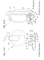
- the present embodiment is an exemplary case that an optical fiber 100 is provided by an optical fiber wiring apparatus 1 on a sheet 101 on which an adhesive layer 101a has been formed.
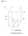
- the optical fiber wiring apparatus 1 includes a wiring unit 2, a horizontal movement mechanism 3 which moves the wiring unit 2 in directions in parallel to the sheet 101 (i.e. the XY directions in Fig. 1 ), a rotation mechanism 4 which rotates the wiring unit 2 about an axis (Z axis in Fig. 1 ) orthogonal to the sheet 101, a holding frame 5, and an unillustrated control unit which controls the horizontal movement mechanism 3 and the rotation mechanism 4.
- the optical fiber 100 of the present embodiment is, for example, about 250 micrometers in diameter.
- the horizontal movement mechanism 3 includes two X-axis frames 10 extending in parallel to the X axis and provided on the holding frame 5, a Y-axis arm 11 provided on the two X-axis frames 10 and extending in parallel to the Y axis, and a carriage 12 attached to the Y-axis arm 11.
- the Y-axis arm 11 is arranged to be movable in the X axis directions by an unillustrated rail on the X-axis frame 10.
- the carriage 12 is also arranged to be movable in the Y axis directions by an unillustrated rail on the Y-axis arm 11.
- the rotation mechanism 4 is attached to the carriage 12. As shown in Fig. 2(a) , This rotation mechanism 4 includes an axial component 13 extending in the Z axis directions and an unillustrated motor rotating the axial component 13. The lower end portion of the axial component 13 is fixed to a later-described unit body 20 of wiring unit 2.
- the unit 2 includes a unit body 20, a bobbin 21 on which an optical fiber 100 is wound, a guide member 22 which guides the optical fiber 100 drawn from the bobbin 21 to the adhesive layer 101a, a wiring roller 24 which presses the optical fiber 100 onto the adhesive layer 101a, a coil spring (elastic member) 30 which biases the wiring roller 24 toward the adhesive layer 101a, and a tension adjusting unit 40 which adjusts the tension of the optical fiber 100.
- the unit body 20 is a short rectangular tube. On the top plate of the unit body 20, the lower end portion of the axial component 13 is fixed. This arrangement allows the wiring unit 2 to be movable in a wiring direction (i.e. in the direction of the arrow A in Fig. 2 and Fig. 3 ) by the horizontal movement mechanism 3 and the rotation mechanism 4.
- the unit body 20 To the unit body 20 is attached to the bobbin 21 on which the optical fiber 100 is wound.
- the bobbin 21 is supported by the unit body 20 to be rotatable about an axis which is in parallel to the sheet 101 and orthogonal to the arrow A (i.e. the axis which is in the B directions in Fig. 2(b) ).
- the optical fiber 100 drawn from the bobbin 21 is supplied to the guide member 22 and the wiring roller 24 via a later-described tension roller 41 of the tension adjusting unit 40.
- the bobbin 21 is provided to be detachable to the unit body 20 and is replaced with a new bobbin 21 when a remaining amount of the wound optical fiber 100 becomes small.
- the bobbin 21 is arranged to be rotatable by a tension generated when the optical fiber 100 is pressed onto the adhesive layer 101a by the wiring roller 24.
- the bobbin 21 has a resistance (rotating torque) with which the bobbin 21 rotates when the optical fiber 100 has a predetermined level of tension but does not rotate under its own inertia. This arrangement makes it possible to stably supply the optical fiber 100 to the wiring roller 24. Moreover, cost reduction is achieved because a motor or the like is not required to rotate the bobbin 21.
- a fixture plate 26 is connected via a below-described linear rail 33 and a slider 34.
- a supporting member 27 and a guide member 22 are fixed to be aligned in the direction of the arrows A.
- the guide member 22 has a rectangular parallelepiped shape and is attached to the fixture plate 26 such that the side surfaces are orthogonal to the directions of the arrows A and B.
- This guide member 22 is arranged to be detachable to the fixture plate 26, and is suitably replaced with a different one in accordance with the diameter and/or number of optical fibers to be used.
- the guide member 22 is replaced also when it is worn out.
- the side surface on the wiring roller 24 side is a back surface 22b, whereas the other side surface is a front surface 22a.
- the distance H between the lower end of the guide member 22 and the surface of the adhesive layer 101a is twice or more longer than the diameter of the optical fiber 100. This arrangement prevents the lower end of the guide member 22 from being caught by a part of the optical fiber 100 having already been provided on the adhesive layer 101a.
- the back surface 22b of the guide member 22 is provided on the axis C of the axial component 13.
- a groove portion 23 is formed to extend from the central part of the front surface 22a in the vertical directions to the lower end of the back surface 22b.
- the groove portion 23 is provided for guiding the optical fiber 100 drawn from the bobbin 21 to the surface of the adhesive layer 101a.
- the groove portion 23 extends along a circle centered on an axis in parallel to the B direction. In other words, the bottom surface of the groove portion 23 is arc-shaped.
- the groove portion 23 is arranged to be shallower toward the both end portions.
- the end portion of the groove portion 23 on the front surface 22a side is an inlet-side end portion 23a
- the end portion of the groove portion 23 on the back surface 22b side is an outlet-side end portion 23b. Since the back surface 22b is on the axis C of the axial component 13 as described above, the outlet-side end portion 23b is also on the axis C of the axial component 13.
- the optical fiber 100 is not required to contact the entirety of the bottom surface of the groove portion 23, as long as it contacts the bottom portion around the outlet-side end portion 23b. In short, the contact length between the optical fiber 100 and the groove portion 23 is short.
- the guide member 22 is either made of a material (e.g. polytetrafluoroethylene) having a lower friction coefficient than the optical fiber 100 or coated its surface with a material having such a low friction coefficient.
- a material e.g. polytetrafluoroethylene
- the wiring roller 24 is rotatably supported by the supporting member 27. This wiring roller 24 is rotatable about an axis which is in parallel to the sheet 101 and orthogonal to the length of the groove portion 23, i.e. rotatable about an axis extending in the B directions.
- the wiring roller 24 is provided for pressing the optical fiber 100 guided by groove portion 23 onto the adhesive layer 101a so as to adhere the optical fiber 100 to the layer 101a.
- An assist roller 25 is provided in proximity to the outlet-side end portion 23b, between the guide member 22 and the wiring roller 24.
- This assist roller 25 is rotatably supported by an assist roller supporting member 28 which extends from the axis of the supporting member 27.
- the assist roller 25 is, in the same manner as the wiring roller 24, rotatable about an axis extending in the B direction.
- the outer diameter of the assist roller is shorter than the outer diameter of the wiring roller 24.
- the assist roller 25 is provided for pressing the optical fiber 100 guided to the surface of the adhesive layer 101a by the groove portion 23 onto the adhesive layer 101a in order to temporally attach the optical fiber 100 on the adhesive layer 101a.
- a compressed coil spring 30 (elastic member) is provided to be vertically extendable.
- This coil spring 30 biases the wiring roller 24 downward to push the roller onto the optical fiber 100, via the fixture plate 26 and the supporting member 27.
- a vertically-extending shaft 31 Inside the coil spring 30 is inserted a vertically-extending shaft 31.
- This shaft 31 has a lower end portion fixed to the fixture plate 26.
- the upper end portion of the shaft 31 penetrates the bottom plate of the unit body 20 and retained by a linear bush 32 attached to the unit body 20.
- the shaft 31 is smoothly movable in the vertical directions by the linear bush 32.
- the fixture plate 26 is smoothly movable in the vertical directions with respect to the unit body 20.
- the wiring roller 24 and the assist roller 25 are arranged to be stably movable in the vertical directions.
- the wiring roller 24 is always biased by the coil spring 30 toward the sheet 101. For this reason, a friction force is generated between the optical fiber 100 and the wiring roller 24 as the wiring unit 2 moves in the wiring direction (indicated by the arrow A), with the result that the wiring roller 24 certainly rotates without sliding on the optical fiber 100, and hence the optical fiber 100 substantially line-contacts the adhesive layer 101a. Furthermore, also in cases where a part of the optical fiber 100 is wired to traverse another part of the optical fiber 100 which has already adhered to the adhesive layer 101a, the wiring roller 24 can certainly presses that part of the optical fiber 100 onto the adhesive layer 101a.
- the tension adjusting unit 40 includes a tension roller 41, a supporting member 42, a coil spring 43, a shaft 44, and a linear bush 45.
- the linear bush 45 is attached to the unit body 20 to retain the shaft 44 which extends in the direction of the arrow A.
- the leading end portion of the shaft 44 in the direction of the arrow A is fixed to the supporting member 42.
- the shaft 44 is smoothly movable by the linear bush 45 in both the direction of the arrow A and the direction opposite thereto.
- the supporting member 42 rotatably supports the tension roller 41.
- the tension roller 41 is rotatable about an axis extending in the B direction.
- an optical fiber 100 drawn from the bobbin 21 is wound.
- a compressed coil spring 43 is provided to be extendable in the direction of the arrow A, and a shaft 44 is inserted into this coil spring 43.
- the coil spring 43 biases the tension roller 41 via the supporting member 42 toward the optical fiber 100 (i.e. biases the supporting member 42 in the direction of the arrow A). Because of these arrangements, the tension roller 41 is smoothly moved in the direction of the arrow A or the direction opposite thereto by the biasing force of the coil spring 43 or the tension of the optical fiber 100.
- the tension roller 41 moves in the direction opposite to the arrow A against the biasing force of the coil spring 43.
- the tension roller 41 moves in the direction of the arrow A by the biasing force of the coil spring 43.
- the optical fiber wiring apparatus 1 As the wiring unit 2 moves in the wiring direction, the optical fiber 100 is drawn from the bobbin 21 by the tension generated when the wiring roller 24 presses the optical fiber 100 onto the adhesive layer 101a, and the optical fiber 100 is guided to the surface of the adhesive layer 101a by the guide member 22.
- the optical fiber 100 guided by the guide member 22 is pressed onto the surface of the adhesive layer 101a by the assist roller 25 and temporally attached thereto, substantially at the position to which the optical fiber 100 is guided. Thereafter, the optical fiber 100 is pressed onto the surface of the adhesive layer 101a by the wiring roller 24 so as to be fully adhered to the surface. In this manner, the optical fiber wiring apparatus 1 wires the optical fiber 100 onto the sheet 101.
- the guide member 22 If the guide member 22 is not provided, it is necessary to form a groove portion to retain the optical fiber 100 on the outer circumferential surface of the wiring roller 24.
- the edge portions (protruding portions) of the respective sides of the groove portion contact a part of the optical fiber 100 having already been wired on the adhesive layer 101a, with the result that the optical fiber 100 is deviated from the intended position and the fiber becomes easily detachable.
- the present embodiment is arranged such that the guide member 22 guiding the optical fiber 100 and the wiring roller 24 pressing the optical fiber 100 onto the adhesive layer 101a are different components.
- the guide member 22 is not provided for pressing the optical fiber 100 onto the adhesive layer 101a, it is possible as described above to provide a gap H which is twice or more wider than the diameter of the optical fiber 100, between the lower end of the guide member 22 and the surface of the adhesive layer 101a. As such, the guide member 22 and the wiring roller 24 do not contact a part of the optical fiber 100 having already been wired and cause the optical fiber 100 to be deviated from the intended position.
- the contact length between the optical fiber 100 and the groove portion 23 is relatively short as described above, whereas the optical fiber 100 substantially line-contacts the wiring roller 24.
- the friction resistance among the optical fiber 100 and the groove portion 23 and wiring roller 24 does not become excessively high, and the optical fiber 100 is not excessively tensioned.
- the optical fiber 100 guided by the groove portion 23 guided to the surface of the adhesive layer 101a is pressed onto the wiring roller 24 and adheres to the adhesive layer 101a, substantially at the position to which the optical fiber 100 is guided.
- the assist roller 25 is provided in proximity to the outlet-side end portion 23b of the groove portion 23, a deviation between the position to which the optical fiber 100 is guided to the groove portion 23 and the position where the optical fiber 100 is pressed onto the adhesive layer is small. In short, the wiring is precisely carried out.
- optical fiber 100 is not twisted because, with the help of the rotation mechanism 4, the wiring unit 2 performs the wiring while rotating such that the wiring direction matches the tangential direction of the wiring pattern.
- the embodiment above is arranged so that the assist roller 25 is provided between the guide member 22 and the wiring roller 24.
- the assist roller 25 may not be provided.
- the wiring roller 24 is preferably provided at a close proximity of the guide member 22.
- the embodiment above is arranged so that the outlet-side end portion 23b of the groove portion 23 is provided on the axis C of the axial component 13.
- the present invention is not limited to this arrangement.
- the shaft center of the assist roller 25 is provided on the axis C of the axial component 13.
- the axis C intersects the shaft center of the assist roller 25. This makes it possible to perform the wiring relatively precisely.
- the embodiment above is arranged so that the optical fiber 100 is provided on the sheet 101 on which the adhesive layer 101a has been formed, by the optical fiber wiring apparatus 1.
- the optical fiber wiring apparatus 1 of the embodiment above may also be used for providing an optical fiber 100 on a substrate on which an adhesive layer has been formed.
Landscapes
- Physics & Mathematics (AREA)
- General Physics & Mathematics (AREA)
- Optics & Photonics (AREA)
- Light Guides In General And Applications Therefor (AREA)
Applications Claiming Priority (2)
| Application Number | Priority Date | Filing Date | Title |
|---|---|---|---|
| JP2008121120A JP2009271291A (ja) | 2008-05-07 | 2008-05-07 | 光ファイバ布線装置 |
| PCT/JP2009/056812 WO2009136526A1 (ja) | 2008-05-07 | 2009-04-01 | 光ファイバ布線装置 |
Publications (2)
| Publication Number | Publication Date |
|---|---|
| EP2284582A1 true EP2284582A1 (de) | 2011-02-16 |
| EP2284582A4 EP2284582A4 (de) | 2012-11-21 |
Family
ID=41264583
Family Applications (1)
| Application Number | Title | Priority Date | Filing Date |
|---|---|---|---|
| EP09742651A Withdrawn EP2284582A4 (de) | 2008-05-07 | 2009-04-01 | Vorrichtung zur glasfaserverkabelung |
Country Status (7)
| Country | Link |
|---|---|
| US (1) | US20110126987A1 (de) |
| EP (1) | EP2284582A4 (de) |
| JP (1) | JP2009271291A (de) |
| KR (1) | KR20110003521A (de) |
| CN (1) | CN102016661A (de) |
| CA (1) | CA2723362A1 (de) |
| WO (1) | WO2009136526A1 (de) |
Cited By (2)
| Publication number | Priority date | Publication date | Assignee | Title |
|---|---|---|---|---|
| ITUB20154208A1 (it) * | 2015-10-07 | 2017-04-07 | Mecstar S R L | APPARATO, METODO E DISPOSITIVO PER LA REALIZZAZIONE DI PRODOTTI INCORPORANTI UN RFid |
| US10628719B2 (en) | 2015-10-07 | 2020-04-21 | Mecstar S.R.L. | Apparatus, method and device for making products incorporating an RFid |
Families Citing this family (25)
| Publication number | Priority date | Publication date | Assignee | Title |
|---|---|---|---|---|
| US11131431B2 (en) | 2014-09-28 | 2021-09-28 | Jiaxing Super Lighting Electric Appliance Co., Ltd | LED tube lamp |
| US10634337B2 (en) | 2014-12-05 | 2020-04-28 | Jiaxing Super Lighting Electric Appliance Co., Ltd | LED tube lamp with heat dissipation of power supply in end cap |
| US10021742B2 (en) | 2014-09-28 | 2018-07-10 | Jiaxing Super Lighting Electric Appliance Co., Ltd | LED tube lamp |
| EP2367036A1 (de) * | 2010-03-02 | 2011-09-21 | BAE Systems PLC | Auf Substraten fixierte optische Fasern |
| EP2542929A1 (de) * | 2010-03-02 | 2013-01-09 | BAE Systems PLC | Auf substraten fixierte glasfaser |
| JP5686895B2 (ja) * | 2010-07-20 | 2015-03-18 | オーエフエス ファイテル,エルエルシー | 顧客施設内における光ファイバー設置 |
| US11480305B2 (en) | 2014-09-25 | 2022-10-25 | Jiaxing Super Lighting Electric Appliance Co., Ltd. | LED tube lamp |
| US10299333B2 (en) | 2014-09-28 | 2019-05-21 | Jiaxing Super Lighting Electric Appliance Co., Ltd. | LED tube lamp |
| US10560989B2 (en) | 2014-09-28 | 2020-02-11 | Jiaxing Super Lighting Electric Appliance Co., Ltd | LED tube lamp |
| CN115095808A (zh) | 2014-09-28 | 2022-09-23 | 嘉兴山蒲照明电器有限公司 | 一种led直管灯 |
| US12264789B2 (en) | 2014-12-05 | 2025-04-01 | Jiaxing Super Lighting Electric Appliance Co., Ltd | LED tube lamp |
| CA2966947C (en) | 2014-12-05 | 2021-05-04 | Jiaxing Super Lighting Electric Appliance Co., Ltd | Led tube lamp |
| US10514134B2 (en) | 2014-12-05 | 2019-12-24 | Jiaxing Super Lighting Electric Appliance Co., Ltd | LED tube lamp |
| US9897265B2 (en) | 2015-03-10 | 2018-02-20 | Jiaxing Super Lighting Electric Appliance Co., Ltd. | LED tube lamp having LED light strip |
| US10161569B2 (en) | 2015-09-02 | 2018-12-25 | Jiaxing Super Lighting Electric Appliance Co., Ltd | LED tube lamp |
| CN105182477B (zh) * | 2015-09-30 | 2017-11-10 | 上海交通大学 | 可控压力精密柔性板布纤装置及布纤方法 |
| CN105242369B (zh) * | 2015-10-12 | 2018-01-02 | 上海交通大学 | 可控压力精密柔性板自动布纤设备及其自动布纤方法 |
| CN105572829A (zh) * | 2015-12-29 | 2016-05-11 | 厦门迈通科技有限公司 | 光纤布纤设备 |
| CN105605444B (zh) * | 2016-03-17 | 2019-07-19 | 嘉兴山蒲照明电器有限公司 | 一种u型led日光灯 |
| CN107202262B (zh) | 2016-03-17 | 2024-04-30 | 嘉兴山蒲照明电器有限公司 | U型led日光灯 |
| CN105759382B (zh) * | 2016-04-06 | 2019-02-26 | 广东中天科技光缆有限公司 | 一种通信光缆的松紧调节结构 |
| CN105842810A (zh) * | 2016-05-31 | 2016-08-10 | 河南宏骏通信工程有限公司 | 一种新型组合式光纤布线装置 |
| JP7248424B2 (ja) * | 2018-12-28 | 2023-03-29 | 日東電工株式会社 | 粘着体送出装置及び粘着体送出方法 |
| CN114275612B (zh) * | 2021-12-27 | 2023-12-22 | 武汉光谷长盈通计量有限公司 | 多轮型光纤螺旋盘绕装置 |
| CN120745175B (zh) * | 2025-06-16 | 2025-12-16 | 西安电子科技大学 | 一种基于线径误差的制导光纤线包含缺陷缠绕建模方法 |
Family Cites Families (13)
| Publication number | Priority date | Publication date | Assignee | Title |
|---|---|---|---|---|
| US3872236A (en) * | 1971-06-11 | 1975-03-18 | Amp Inc | Bonded wire i interconnection system |
| US4000558A (en) * | 1971-10-14 | 1977-01-04 | International Telephone And Telegraph Corporation | Process of fabricating wiring harness |
| DE2519054C3 (de) * | 1974-04-30 | 1978-08-03 | Central Glass Co., Ltd., Ube, Yamaguchi (Japan) | Vorrichtung zum Aufbringen eines Drahtes auf eine Trägerfolie aus thermoplastischem Kunststoff nach einem vorgegebenen Muster |
| US4691987A (en) * | 1983-07-08 | 1987-09-08 | Itek Graphix Corp. | Optical fiber cable producer and method of bonding optical fibers to light emitting diodes |
| US5259051A (en) * | 1992-08-28 | 1993-11-02 | At&T Bell Laboratories | Optical fiber interconnection apparatus and methods of making interconnections |
| US5421930A (en) * | 1993-11-01 | 1995-06-06 | American Telephone And Telegraph Company | Optical fiber routing method and apparatus |
| US5917180A (en) | 1997-07-16 | 1999-06-29 | Canadian Space Agency | Pressure sensor based on illumination of a deformable integrating cavity |
| EP1061393A1 (de) * | 1999-06-17 | 2000-12-20 | Nippon Telegraph and Telephone Corporation | Faser optische Verdrahtungs Apparat und Verfahren zum Verdrahten eine optische Faser |
| JP3706902B2 (ja) | 1999-06-17 | 2005-10-19 | 日本電信電話株式会社 | 光ファイバ布線装置と光ファイバ布線方法 |
| JP2001255420A (ja) * | 2000-03-10 | 2001-09-21 | Fujikura Ltd | 光ファイバ布線ヘッド |
| JP2001255421A (ja) * | 2000-03-10 | 2001-09-21 | Fujikura Ltd | 光ファイバ布線ヘッド |
| AU2001270016A1 (en) * | 2000-06-26 | 2002-01-08 | Fiberconnex Corporation | Optical fiber dispensing, routing and termination apparatus and method |
| JP4018600B2 (ja) * | 2003-06-27 | 2007-12-05 | 株式会社巴川製紙所 | 光ファイバ配線装置及び配線方法 |
-
2008
- 2008-05-07 JP JP2008121120A patent/JP2009271291A/ja active Pending
-
2009
- 2009-04-01 CN CN2009801165441A patent/CN102016661A/zh active Pending
- 2009-04-01 WO PCT/JP2009/056812 patent/WO2009136526A1/ja not_active Ceased
- 2009-04-01 KR KR1020107024911A patent/KR20110003521A/ko not_active Withdrawn
- 2009-04-01 CA CA2723362A patent/CA2723362A1/en not_active Abandoned
- 2009-04-01 US US12/990,685 patent/US20110126987A1/en not_active Abandoned
- 2009-04-01 EP EP09742651A patent/EP2284582A4/de not_active Withdrawn
Cited By (4)
| Publication number | Priority date | Publication date | Assignee | Title |
|---|---|---|---|---|
| ITUB20154208A1 (it) * | 2015-10-07 | 2017-04-07 | Mecstar S R L | APPARATO, METODO E DISPOSITIVO PER LA REALIZZAZIONE DI PRODOTTI INCORPORANTI UN RFid |
| EP3154329A1 (de) | 2015-10-07 | 2017-04-12 | Mecstar S.r.l. | Vorrichtung, verfahren und einrichtung zur herstellung von produkten mit rfid |
| US10455705B2 (en) | 2015-10-07 | 2019-10-22 | Mecstar S.R.L. | Apparatus, method and device for making products incorporating an RFid |
| US10628719B2 (en) | 2015-10-07 | 2020-04-21 | Mecstar S.R.L. | Apparatus, method and device for making products incorporating an RFid |
Also Published As
| Publication number | Publication date |
|---|---|
| CA2723362A1 (en) | 2009-11-12 |
| US20110126987A1 (en) | 2011-06-02 |
| KR20110003521A (ko) | 2011-01-12 |
| EP2284582A4 (de) | 2012-11-21 |
| WO2009136526A1 (ja) | 2009-11-12 |
| CN102016661A (zh) | 2011-04-13 |
| JP2009271291A (ja) | 2009-11-19 |
Similar Documents
| Publication | Publication Date | Title |
|---|---|---|
| EP2284582A1 (de) | Vorrichtung zur glasfaserverkabelung | |
| US10011034B2 (en) | Cutting plotter | |
| EP2712830B1 (de) | Changierarm und Garnwickelmaschine damit | |
| JP5149683B2 (ja) | 溶射装置におけるワイヤ送給機構 | |
| EP1061393A1 (de) | Faser optische Verdrahtungs Apparat und Verfahren zum Verdrahten eine optische Faser | |
| CN110902484A (zh) | 用于在卷绕装置中转动线筒的方法和装置 | |
| WO2016136420A1 (ja) | コイルばね製造装置と、コイルばねの製造方法 | |
| JP4446142B2 (ja) | 光ファイバ切断装置および切断方法 | |
| KR20210028691A (ko) | 리드선 인출 장치 | |
| JP2001059910A (ja) | 光ファイバ布線装置と光ファイバ布線方法 | |
| JP2652822B2 (ja) | 光ファイバーの整列方法および装置 | |
| US20200225136A1 (en) | Thread guide wear testing machine and thread guide wear testing method | |
| JP2005203551A (ja) | 巻線装置 | |
| JP3115286B1 (ja) | 巻取装置 | |
| JP2020014287A (ja) | 巻線装置 | |
| JP7544035B2 (ja) | ファイバープレイスメント装置 | |
| JP2006137512A (ja) | 金属線供給装置 | |
| CN114424305A (zh) | 线材配设装置以及线材配设方法 | |
| JPS60143935A (ja) | 円筒形の構造体を繊維で補強された合成物質を巻取ることにより形成するための巻取り機 | |
| JP2580276B2 (ja) | 巻線用テ―ピング装置 | |
| JP7531962B1 (ja) | 除塵装置 | |
| US20260021994A1 (en) | Threadlike adhesive sticking apparatus and threadlike adhesive sticking method | |
| JP4018600B2 (ja) | 光ファイバ配線装置及び配線方法 | |
| JP6935727B2 (ja) | 識別糸付着装置 | |
| CN116018664B (zh) | 操控台的倾斜元件 |
Legal Events
| Date | Code | Title | Description |
|---|---|---|---|
| PUAI | Public reference made under article 153(3) epc to a published international application that has entered the european phase |
Free format text: ORIGINAL CODE: 0009012 |
|
| 17P | Request for examination filed |
Effective date: 20101207 |
|
| AK | Designated contracting states |
Kind code of ref document: A1 Designated state(s): AT BE BG CH CY CZ DE DK EE ES FI FR GB GR HR HU IE IS IT LI LT LU LV MC MK MT NL NO PL PT RO SE SI SK TR |
|
| AX | Request for extension of the european patent |
Extension state: AL BA RS |
|
| DAX | Request for extension of the european patent (deleted) | ||
| A4 | Supplementary search report drawn up and despatched |
Effective date: 20121022 |
|
| RIC1 | Information provided on ipc code assigned before grant |
Ipc: G02B 6/36 20060101AFI20121016BHEP |
|
| STAA | Information on the status of an ep patent application or granted ep patent |
Free format text: STATUS: THE APPLICATION IS DEEMED TO BE WITHDRAWN |
|
| 18D | Application deemed to be withdrawn |
Effective date: 20121101 |