EP2284599B1 - Methode zum Herstellen einer polarisierenden Brillenlinse - Google Patents
Methode zum Herstellen einer polarisierenden Brillenlinse Download PDFInfo
- Publication number
- EP2284599B1 EP2284599B1 EP10172025A EP10172025A EP2284599B1 EP 2284599 B1 EP2284599 B1 EP 2284599B1 EP 10172025 A EP10172025 A EP 10172025A EP 10172025 A EP10172025 A EP 10172025A EP 2284599 B1 EP2284599 B1 EP 2284599B1
- Authority
- EP
- European Patent Office
- Prior art keywords
- substrate
- polarizing
- rubbing
- orientation layer
- layer
- Prior art date
- Legal status (The legal status is an assumption and is not a legal conclusion. Google has not performed a legal analysis and makes no representation as to the accuracy of the status listed.)
- Not-in-force
Links
- 238000004519 manufacturing process Methods 0.000 title claims description 57
- 239000000758 substrate Substances 0.000 claims description 162
- 238000006073 displacement reaction Methods 0.000 claims description 84
- 238000000151 deposition Methods 0.000 claims description 6
- 230000003100 immobilizing effect Effects 0.000 claims description 2
- 239000010410 layer Substances 0.000 description 181
- 230000010287 polarization Effects 0.000 description 99
- 239000000975 dye Substances 0.000 description 56
- 239000010408 film Substances 0.000 description 56
- 238000000034 method Methods 0.000 description 30
- 239000011248 coating agent Substances 0.000 description 28
- 238000000576 coating method Methods 0.000 description 28
- 238000012545 processing Methods 0.000 description 28
- 230000015572 biosynthetic process Effects 0.000 description 25
- VYPSYNLAJGMNEJ-UHFFFAOYSA-N Silicium dioxide Chemical compound O=[Si]=O VYPSYNLAJGMNEJ-UHFFFAOYSA-N 0.000 description 24
- 239000002002 slurry Substances 0.000 description 23
- 238000012986 modification Methods 0.000 description 22
- 230000004048 modification Effects 0.000 description 22
- XLYOFNOQVPJJNP-UHFFFAOYSA-N water Substances O XLYOFNOQVPJJNP-UHFFFAOYSA-N 0.000 description 22
- 239000000463 material Substances 0.000 description 20
- 210000003128 head Anatomy 0.000 description 16
- 239000007788 liquid Substances 0.000 description 14
- 239000004973 liquid crystal related substance Substances 0.000 description 14
- 239000002245 particle Substances 0.000 description 14
- 239000002904 solvent Substances 0.000 description 13
- 239000011241 protective layer Substances 0.000 description 11
- 239000000377 silicon dioxide Substances 0.000 description 11
- 239000007864 aqueous solution Substances 0.000 description 10
- 230000008859 change Effects 0.000 description 9
- 230000000694 effects Effects 0.000 description 9
- 230000006870 function Effects 0.000 description 9
- 230000003287 optical effect Effects 0.000 description 9
- 238000004528 spin coating Methods 0.000 description 9
- 150000001875 compounds Chemical class 0.000 description 8
- 229920001971 elastomer Polymers 0.000 description 8
- TWNQGVIAIRXVLR-UHFFFAOYSA-N oxo(oxoalumanyloxy)alumane Chemical compound O=[Al]O[Al]=O TWNQGVIAIRXVLR-UHFFFAOYSA-N 0.000 description 8
- 230000000052 comparative effect Effects 0.000 description 7
- 229920001577 copolymer Polymers 0.000 description 7
- 239000000203 mixture Substances 0.000 description 7
- 238000012856 packing Methods 0.000 description 7
- 230000008569 process Effects 0.000 description 7
- 238000007740 vapor deposition Methods 0.000 description 7
- 230000000903 blocking effect Effects 0.000 description 6
- 238000010586 diagram Methods 0.000 description 6
- 238000009826 distribution Methods 0.000 description 6
- 239000000178 monomer Substances 0.000 description 6
- 239000000126 substance Substances 0.000 description 6
- 230000003667 anti-reflective effect Effects 0.000 description 5
- 238000011156 evaluation Methods 0.000 description 5
- 239000011521 glass Substances 0.000 description 5
- 239000003921 oil Substances 0.000 description 5
- 238000002834 transmittance Methods 0.000 description 5
- VSCWAEJMTAWNJL-UHFFFAOYSA-K aluminium trichloride Chemical compound Cl[Al](Cl)Cl VSCWAEJMTAWNJL-UHFFFAOYSA-K 0.000 description 4
- 125000004432 carbon atom Chemical group C* 0.000 description 4
- 239000003795 chemical substances by application Substances 0.000 description 4
- 239000013013 elastic material Substances 0.000 description 4
- 210000001508 eye Anatomy 0.000 description 4
- 230000004313 glare Effects 0.000 description 4
- 229910052809 inorganic oxide Inorganic materials 0.000 description 4
- 238000005259 measurement Methods 0.000 description 4
- -1 polyethylene terephthalate Polymers 0.000 description 4
- 239000005871 repellent Substances 0.000 description 4
- 150000003377 silicon compounds Chemical class 0.000 description 4
- 239000010409 thin film Substances 0.000 description 4
- JOYRKODLDBILNP-UHFFFAOYSA-N Ethyl urethane Chemical compound CCOC(N)=O JOYRKODLDBILNP-UHFFFAOYSA-N 0.000 description 3
- OKKJLVBELUTLKV-UHFFFAOYSA-N Methanol Chemical compound OC OKKJLVBELUTLKV-UHFFFAOYSA-N 0.000 description 3
- 239000003082 abrasive agent Substances 0.000 description 3
- 238000010521 absorption reaction Methods 0.000 description 3
- 239000000654 additive Substances 0.000 description 3
- 125000000217 alkyl group Chemical group 0.000 description 3
- 230000002457 bidirectional effect Effects 0.000 description 3
- 210000005252 bulbus oculi Anatomy 0.000 description 3
- 239000003054 catalyst Substances 0.000 description 3
- 238000007598 dipping method Methods 0.000 description 3
- 125000001495 ethyl group Chemical group [H]C([H])([H])C([H])([H])* 0.000 description 3
- 239000006260 foam Substances 0.000 description 3
- 229920001519 homopolymer Polymers 0.000 description 3
- 230000031700 light absorption Effects 0.000 description 3
- 125000002496 methyl group Chemical group [H]C([H])([H])* 0.000 description 3
- 239000011268 mixed slurry Substances 0.000 description 3
- RVTZCBVAJQQJTK-UHFFFAOYSA-N oxygen(2-);zirconium(4+) Chemical compound [O-2].[O-2].[Zr+4] RVTZCBVAJQQJTK-UHFFFAOYSA-N 0.000 description 3
- 229920003023 plastic Polymers 0.000 description 3
- 239000004033 plastic Substances 0.000 description 3
- 229920003226 polyurethane urea Polymers 0.000 description 3
- 230000000750 progressive effect Effects 0.000 description 3
- 229920005989 resin Polymers 0.000 description 3
- 239000011347 resin Substances 0.000 description 3
- 238000005507 spraying Methods 0.000 description 3
- 229910001928 zirconium oxide Inorganic materials 0.000 description 3
- AZQWKYJCGOJGHM-UHFFFAOYSA-N 1,4-benzoquinone Chemical compound O=C1C=CC(=O)C=C1 AZQWKYJCGOJGHM-UHFFFAOYSA-N 0.000 description 2
- LFQSCWFLJHTTHZ-UHFFFAOYSA-N Ethanol Chemical compound CCO LFQSCWFLJHTTHZ-UHFFFAOYSA-N 0.000 description 2
- VEXZGXHMUGYJMC-UHFFFAOYSA-N Hydrochloric acid Chemical compound Cl VEXZGXHMUGYJMC-UHFFFAOYSA-N 0.000 description 2
- VVQNEPGJFQJSBK-UHFFFAOYSA-N Methyl methacrylate Chemical compound COC(=O)C(C)=C VVQNEPGJFQJSBK-UHFFFAOYSA-N 0.000 description 2
- BOTDANWDWHJENH-UHFFFAOYSA-N Tetraethyl orthosilicate Chemical compound CCO[Si](OCC)(OCC)OCC BOTDANWDWHJENH-UHFFFAOYSA-N 0.000 description 2
- GWEVSGVZZGPLCZ-UHFFFAOYSA-N Titan oxide Chemical compound O=[Ti]=O GWEVSGVZZGPLCZ-UHFFFAOYSA-N 0.000 description 2
- 239000002390 adhesive tape Substances 0.000 description 2
- 229910052782 aluminium Inorganic materials 0.000 description 2
- 239000007900 aqueous suspension Substances 0.000 description 2
- SYFOAKAXGNMQAX-UHFFFAOYSA-N bis(prop-2-enyl) carbonate;2-(2-hydroxyethoxy)ethanol Chemical compound OCCOCCO.C=CCOC(=O)OCC=C SYFOAKAXGNMQAX-UHFFFAOYSA-N 0.000 description 2
- YKYOUMDCQGMQQO-UHFFFAOYSA-L cadmium dichloride Chemical compound Cl[Cd]Cl YKYOUMDCQGMQQO-UHFFFAOYSA-L 0.000 description 2
- 239000008199 coating composition Substances 0.000 description 2
- 238000012937 correction Methods 0.000 description 2
- 230000007423 decrease Effects 0.000 description 2
- 238000001514 detection method Methods 0.000 description 2
- 230000002708 enhancing effect Effects 0.000 description 2
- 230000001747 exhibiting effect Effects 0.000 description 2
- 125000000524 functional group Chemical group 0.000 description 2
- 229910052751 metal Inorganic materials 0.000 description 2
- 239000002184 metal Substances 0.000 description 2
- 229910044991 metal oxide Inorganic materials 0.000 description 2
- 150000004706 metal oxides Chemical class 0.000 description 2
- 239000011368 organic material Substances 0.000 description 2
- SIWVEOZUMHYXCS-UHFFFAOYSA-N oxo(oxoyttriooxy)yttrium Chemical compound O=[Y]O[Y]=O SIWVEOZUMHYXCS-UHFFFAOYSA-N 0.000 description 2
- 239000005077 polysulfide Substances 0.000 description 2
- 229920001021 polysulfide Polymers 0.000 description 2
- 150000008117 polysulfides Polymers 0.000 description 2
- 229920002635 polyurethane Polymers 0.000 description 2
- 239000004814 polyurethane Substances 0.000 description 2
- 150000003839 salts Chemical class 0.000 description 2
- LIVNPJMFVYWSIS-UHFFFAOYSA-N silicon monoxide Chemical compound [Si-]#[O+] LIVNPJMFVYWSIS-UHFFFAOYSA-N 0.000 description 2
- 229910052814 silicon oxide Inorganic materials 0.000 description 2
- BPSIOYPQMFLKFR-UHFFFAOYSA-N trimethoxy-[3-(oxiran-2-ylmethoxy)propyl]silane Chemical compound CO[Si](OC)(OC)CCCOCC1CO1 BPSIOYPQMFLKFR-UHFFFAOYSA-N 0.000 description 2
- 239000011592 zinc chloride Substances 0.000 description 2
- JIAARYAFYJHUJI-UHFFFAOYSA-L zinc dichloride Chemical compound [Cl-].[Cl-].[Zn+2] JIAARYAFYJHUJI-UHFFFAOYSA-L 0.000 description 2
- WYTZZXDRDKSJID-UHFFFAOYSA-N (3-aminopropyl)triethoxysilane Chemical compound CCO[Si](OCC)(OCC)CCCN WYTZZXDRDKSJID-UHFFFAOYSA-N 0.000 description 1
- ZCYVEMRRCGMTRW-UHFFFAOYSA-N 7553-56-2 Chemical compound [I] ZCYVEMRRCGMTRW-UHFFFAOYSA-N 0.000 description 1
- 241000511976 Hoya Species 0.000 description 1
- 235000000177 Indigofera tinctoria Nutrition 0.000 description 1
- 229910021577 Iron(II) chloride Inorganic materials 0.000 description 1
- VKEQBMCRQDSRET-UHFFFAOYSA-N Methylone Chemical compound CNC(C)C(=O)C1=CC=C2OCOC2=C1 VKEQBMCRQDSRET-UHFFFAOYSA-N 0.000 description 1
- 241000233805 Phoenix Species 0.000 description 1
- 239000004642 Polyimide Substances 0.000 description 1
- 239000004793 Polystyrene Substances 0.000 description 1
- 229910002808 Si–O–Si Inorganic materials 0.000 description 1
- PJANXHGTPQOBST-VAWYXSNFSA-N Stilbene Natural products C=1C=CC=CC=1/C=C/C1=CC=CC=C1 PJANXHGTPQOBST-VAWYXSNFSA-N 0.000 description 1
- UCKMPCXJQFINFW-UHFFFAOYSA-N Sulphide Chemical compound [S-2] UCKMPCXJQFINFW-UHFFFAOYSA-N 0.000 description 1
- DPOPAJRDYZGTIR-UHFFFAOYSA-N Tetrazine Chemical compound C1=CN=NN=N1 DPOPAJRDYZGTIR-UHFFFAOYSA-N 0.000 description 1
- 239000002253 acid Substances 0.000 description 1
- 239000000853 adhesive Substances 0.000 description 1
- 230000001070 adhesive effect Effects 0.000 description 1
- 239000003513 alkali Substances 0.000 description 1
- XAGFODPZIPBFFR-UHFFFAOYSA-N aluminium Chemical compound [Al] XAGFODPZIPBFFR-UHFFFAOYSA-N 0.000 description 1
- 125000003277 amino group Chemical group 0.000 description 1
- PYKYMHQGRFAEBM-UHFFFAOYSA-N anthraquinone Natural products CCC(=O)c1c(O)c2C(=O)C3C(C=CC=C3O)C(=O)c2cc1CC(=O)OC PYKYMHQGRFAEBM-UHFFFAOYSA-N 0.000 description 1
- 150000004056 anthraquinones Chemical class 0.000 description 1
- 230000003466 anti-cipated effect Effects 0.000 description 1
- 229910052787 antimony Inorganic materials 0.000 description 1
- 239000003125 aqueous solvent Substances 0.000 description 1
- 125000000751 azo group Chemical group [*]N=N[*] 0.000 description 1
- WDIHJSXYQDMJHN-UHFFFAOYSA-L barium chloride Chemical compound [Cl-].[Cl-].[Ba+2] WDIHJSXYQDMJHN-UHFFFAOYSA-L 0.000 description 1
- 229910001626 barium chloride Inorganic materials 0.000 description 1
- 239000002585 base Substances 0.000 description 1
- HFACYLZERDEVSX-UHFFFAOYSA-N benzidine Chemical compound C1=CC(N)=CC=C1C1=CC=C(N)C=C1 HFACYLZERDEVSX-UHFFFAOYSA-N 0.000 description 1
- 238000009835 boiling Methods 0.000 description 1
- 125000000484 butyl group Chemical group [H]C([*])([H])C([H])([H])C([H])([H])C([H])([H])[H] 0.000 description 1
- AXCZMVOFGPJBDE-UHFFFAOYSA-L calcium dihydroxide Chemical compound [OH-].[OH-].[Ca+2] AXCZMVOFGPJBDE-UHFFFAOYSA-L 0.000 description 1
- 239000000920 calcium hydroxide Substances 0.000 description 1
- 229910001861 calcium hydroxide Inorganic materials 0.000 description 1
- 238000006243 chemical reaction Methods 0.000 description 1
- 239000012459 cleaning agent Substances 0.000 description 1
- 239000000084 colloidal system Substances 0.000 description 1
- 238000001816 cooling Methods 0.000 description 1
- 238000005336 cracking Methods 0.000 description 1
- 238000004132 cross linking Methods 0.000 description 1
- 239000003431 cross linking reagent Substances 0.000 description 1
- 125000006165 cyclic alkyl group Chemical group 0.000 description 1
- 125000001511 cyclopentyl group Chemical group [H]C1([H])C([H])([H])C([H])([H])C([H])(*)C1([H])[H] 0.000 description 1
- 230000002950 deficient Effects 0.000 description 1
- 230000008021 deposition Effects 0.000 description 1
- 230000003292 diminished effect Effects 0.000 description 1
- 238000003618 dip coating Methods 0.000 description 1
- 238000001035 drying Methods 0.000 description 1
- 125000003700 epoxy group Chemical group 0.000 description 1
- 210000000887 face Anatomy 0.000 description 1
- 239000006261 foam material Substances 0.000 description 1
- 229910052732 germanium Inorganic materials 0.000 description 1
- 230000003760 hair shine Effects 0.000 description 1
- 229910052736 halogen Inorganic materials 0.000 description 1
- 125000003187 heptyl group Chemical group [H]C([*])([H])C([H])([H])C([H])([H])C([H])([H])C([H])([H])C([H])([H])C([H])([H])[H] 0.000 description 1
- 125000004051 hexyl group Chemical group [H]C([H])([H])C([H])([H])C([H])([H])C([H])([H])C([H])([H])C([H])([H])* 0.000 description 1
- 238000006460 hydrolysis reaction Methods 0.000 description 1
- 229940097275 indigo Drugs 0.000 description 1
- COHYTHOBJLSHDF-UHFFFAOYSA-N indigo powder Natural products N1C2=CC=CC=C2C(=O)C1=C1C(=O)C2=CC=CC=C2N1 COHYTHOBJLSHDF-UHFFFAOYSA-N 0.000 description 1
- 229910052738 indium Inorganic materials 0.000 description 1
- 239000004615 ingredient Substances 0.000 description 1
- PNDPGZBMCMUPRI-UHFFFAOYSA-N iodine Chemical compound II PNDPGZBMCMUPRI-UHFFFAOYSA-N 0.000 description 1
- 229910052740 iodine Inorganic materials 0.000 description 1
- 239000011630 iodine Substances 0.000 description 1
- FBAFATDZDUQKNH-UHFFFAOYSA-M iron chloride Chemical compound [Cl-].[Fe] FBAFATDZDUQKNH-UHFFFAOYSA-M 0.000 description 1
- NMCUIPGRVMDVDB-UHFFFAOYSA-L iron dichloride Chemical compound Cl[Fe]Cl NMCUIPGRVMDVDB-UHFFFAOYSA-L 0.000 description 1
- 125000000959 isobutyl group Chemical group [H]C([H])([H])C([H])(C([H])([H])[H])C([H])([H])* 0.000 description 1
- IQPQWNKOIGAROB-UHFFFAOYSA-N isocyanate group Chemical group [N-]=C=O IQPQWNKOIGAROB-UHFFFAOYSA-N 0.000 description 1
- 125000001449 isopropyl group Chemical group [H]C([H])([H])C([H])(*)C([H])([H])[H] 0.000 description 1
- 230000002535 lyotropic effect Effects 0.000 description 1
- 230000007246 mechanism Effects 0.000 description 1
- 230000005499 meniscus Effects 0.000 description 1
- DZVCFNFOPIZQKX-LTHRDKTGSA-M merocyanine Chemical compound [Na+].O=C1N(CCCC)C(=O)N(CCCC)C(=O)C1=C\C=C\C=C/1N(CCCS([O-])(=O)=O)C2=CC=CC=C2O\1 DZVCFNFOPIZQKX-LTHRDKTGSA-M 0.000 description 1
- 238000002156 mixing Methods 0.000 description 1
- 125000004108 n-butyl group Chemical group [H]C([H])([H])C([H])([H])C([H])([H])C([H])([H])* 0.000 description 1
- 125000004123 n-propyl group Chemical group [H]C([H])([H])C([H])([H])C([H])([H])* 0.000 description 1
- 229910052758 niobium Inorganic materials 0.000 description 1
- 239000010955 niobium Substances 0.000 description 1
- URLJKFSTXLNXLG-UHFFFAOYSA-N niobium(5+);oxygen(2-) Chemical compound [O-2].[O-2].[O-2].[O-2].[O-2].[Nb+5].[Nb+5] URLJKFSTXLNXLG-UHFFFAOYSA-N 0.000 description 1
- 125000002347 octyl group Chemical group [H]C([*])([H])C([H])([H])C([H])([H])C([H])([H])C([H])([H])C([H])([H])C([H])([H])C([H])([H])[H] 0.000 description 1
- 150000002894 organic compounds Chemical class 0.000 description 1
- 125000000962 organic group Chemical group 0.000 description 1
- 239000003960 organic solvent Substances 0.000 description 1
- 239000003002 pH adjusting agent Substances 0.000 description 1
- 125000001147 pentyl group Chemical group C(CCCC)* 0.000 description 1
- 125000002080 perylenyl group Chemical group C1(=CC=C2C=CC=C3C4=CC=CC5=CC=CC(C1=C23)=C45)* 0.000 description 1
- CSHWQDPOILHKBI-UHFFFAOYSA-N peryrene Natural products C1=CC(C2=CC=CC=3C2=C2C=CC=3)=C3C2=CC=CC3=C1 CSHWQDPOILHKBI-UHFFFAOYSA-N 0.000 description 1
- 239000004014 plasticizer Substances 0.000 description 1
- 238000005498 polishing Methods 0.000 description 1
- 229920000515 polycarbonate Polymers 0.000 description 1
- 239000004417 polycarbonate Substances 0.000 description 1
- 229920000139 polyethylene terephthalate Polymers 0.000 description 1
- 239000005020 polyethylene terephthalate Substances 0.000 description 1
- 229920001721 polyimide Polymers 0.000 description 1
- 229920000642 polymer Polymers 0.000 description 1
- 229920002223 polystyrene Polymers 0.000 description 1
- 229920002578 polythiourethane polymer Polymers 0.000 description 1
- 229920000915 polyvinyl chloride Polymers 0.000 description 1
- 239000004800 polyvinyl chloride Substances 0.000 description 1
- 238000002360 preparation method Methods 0.000 description 1
- 238000003825 pressing Methods 0.000 description 1
- 239000011164 primary particle Substances 0.000 description 1
- 125000001436 propyl group Chemical group [H]C([*])([H])C([H])([H])C([H])([H])[H] 0.000 description 1
- 230000001681 protective effect Effects 0.000 description 1
- IZMJMCDDWKSTTK-UHFFFAOYSA-N quinoline yellow Chemical compound C1=CC=CC2=NC(C3C(C4=CC=CC=C4C3=O)=O)=CC=C21 IZMJMCDDWKSTTK-UHFFFAOYSA-N 0.000 description 1
- 230000005855 radiation Effects 0.000 description 1
- 230000002940 repellent Effects 0.000 description 1
- 238000011160 research Methods 0.000 description 1
- 238000005488 sandblasting Methods 0.000 description 1
- 238000006748 scratching Methods 0.000 description 1
- 230000002393 scratching effect Effects 0.000 description 1
- 125000002914 sec-butyl group Chemical group [H]C([H])([H])C([H])([H])C([H])(*)C([H])([H])[H] 0.000 description 1
- 230000035807 sensation Effects 0.000 description 1
- 238000000926 separation method Methods 0.000 description 1
- RMAQACBXLXPBSY-UHFFFAOYSA-N silicic acid Chemical compound O[Si](O)(O)O RMAQACBXLXPBSY-UHFFFAOYSA-N 0.000 description 1
- 229910052710 silicon Inorganic materials 0.000 description 1
- 235000012239 silicon dioxide Nutrition 0.000 description 1
- 239000002356 single layer Substances 0.000 description 1
- 238000003980 solgel method Methods 0.000 description 1
- 239000007787 solid Substances 0.000 description 1
- PJANXHGTPQOBST-UHFFFAOYSA-N stilbene Chemical compound C=1C=CC=CC=1C=CC1=CC=CC=C1 PJANXHGTPQOBST-UHFFFAOYSA-N 0.000 description 1
- 235000021286 stilbenes Nutrition 0.000 description 1
- 125000005504 styryl group Chemical group 0.000 description 1
- 229910052715 tantalum Inorganic materials 0.000 description 1
- 125000000999 tert-butyl group Chemical group [H]C([H])([H])C(*)(C([H])([H])[H])C([H])([H])[H] 0.000 description 1
- 238000012360 testing method Methods 0.000 description 1
- 229910052718 tin Inorganic materials 0.000 description 1
- 229910052719 titanium Inorganic materials 0.000 description 1
- 238000013519 translation Methods 0.000 description 1
- 239000012780 transparent material Substances 0.000 description 1
- 238000009281 ultraviolet germicidal irradiation Methods 0.000 description 1
- 229920006305 unsaturated polyester Polymers 0.000 description 1
- 238000001771 vacuum deposition Methods 0.000 description 1
- 229910052720 vanadium Inorganic materials 0.000 description 1
- 229910052727 yttrium Inorganic materials 0.000 description 1
- 229910052725 zinc Inorganic materials 0.000 description 1
- 229910052726 zirconium Inorganic materials 0.000 description 1
Images




Classifications
-
- G—PHYSICS
- G02—OPTICS
- G02C—SPECTACLES; SUNGLASSES OR GOGGLES INSOFAR AS THEY HAVE THE SAME FEATURES AS SPECTACLES; CONTACT LENSES
- G02C7/00—Optical parts
- G02C7/12—Polarisers
Definitions
- the present invention relates to a method of manufacturing a polarizing eyeglass lens functioning to absorb or transmit light of a specific direction of polarization for the purpose of blocking light such as reflected light having a specific direction of polarization outdoors or the like.
- polarizing elements that pass or block only those components of incident light that are polarized in specific directions have come into use.
- glass elements that comprise multilayered films and diffraction gratings comprised of organic birefringent materials.
- Dichroic polarizing elements are employed in display devices such as liquid-crystal displays (LCDs) to increase contrast. They are manufactured by the method of tinting a film with a dichroic material such as iodine, crosslinking the film with a crosslinking agent, and uniaxially extending the film.
- polarizing elements can be manufactured by the method of coating a dichroic dye on an orientation layer on a substrate. This method utilizes the fact that water-soluble dichroic dyes exhibit liquid crystal properties based on concentration when dissolved in an aqueous solvent. When a coating material containing dichroic dyes exhibiting liquid crystal properties is coated on an orientation layer, uniform orientation of the liquid crystals is achieved and the dichroic dye in the coating film is uniaxially oriented. A thin film containing uniaxially oriented dichroic dye can be used as a polarizing element to achieve a polarizing function.
- WO2006/081006 discloses providing an orientation layer in the form of an inorganic intermediate layer between a transparent substrate and a polarizing layer in a polarizing product having a polarizing layer and a protective layer on the surface of a transparent substrate.
- the inorganic intermediate layer functions to strengthen adhesion between the polarizing layer and the substrate, and that silica (SiO 2 ) is suitable as a material for forming the inorganic intermediate layer.
- Polarizing elements are used in manufactured products in addition to the above electronic devices and the like.
- US2008/0252846A1 and Family member U.S. Patent No. 7,597,442 propose a polarizing eyeglass lens incorporating a polarizing filter.
- US2008/0252846A1 the lens is divided into several zones and a polarizing filter with a different direction of polarization axis is provided in each zone to protect the eye of the wearer of the lens from the glare of reflected light.
- US2008/0252846A1 also discloses a method of manufacturing a polarizing lens comprising a customizing step of distinguishing between a type of lens wearer who moves the eyes themselves while exploring the environment and a type of lens wearer who moves his head, and varying the size of the zones on that basis.
- the polarizing lens that is proposed in US2008/0252846A1 envisions vertically polarized light entering the lens from a direction precisely horizontal to the user, and horizontally polarized light entering from above.
- light becomes vertically polarized when it reflects off of the lateral surfaces of buildings and the like when the sun is low, such as at dawn and dusk.
- Horizontally polarized light from above strikes the wearer when the wearer and the position of the sun are aligned in a direction that is perpendicular to the surface of reflection.
- the polarizing lens of US2008/0252846A1 is incapable of fully blocking diagonally polarized light that enters from such diagonal directions. Most such light ends up being passed. Further, the daily living environment is comprised not just of smooth reflective surfaces such as building glass and panels, but also of the curved, glossy surfaces of vehicles and the like. The polarizing lens of US2008/0252846Al cannot block the light containing complex directions of polarization that is reflected off of such surfaces.
- An aspect of the present invention provides for a method of manufacturing a polarizing eyeglass lens that can block light having different directions of polarization that enters from various directions.
- An aspect of the present invention relates to a method of manufacturing a polarizing eyeglass lens (also referred to as simply a "polarizing lens” hereinafter) comprising:
- one of the rubbing member and the substrate can be secured and the other of the two can be slid using a displacement reference at a given position as a center of revolution with the rubbing member in a state of contact with the orientation layer.
- either the substrate or the rubbing member imparting rubbing traces to the surface of the orientation layer is moved in revolving fashion about a displacement reference at a given position, and slid by means of equidistant movement to form rubbing traces. That is, in one embodiment of the present invention, curved rubbing traces such as arcs or concentric circles can be formed by the above-described sliding on the surface of the orientation layer, and a dichroic dye can be deposited and oriented on the orientation layer having rubbing traces to form a polarizing layer at least a portion of polarization axes of which are curved.
- arc-shaped rubbing traces can be formed on the surface of the orientation layer by revolving either the substrate or the rubbing member. Additionally, when the displacement reference is positioned on the substrate, rubbing traces in the form of concentric circles centered on the displacement reference can be formed on the surface of the orientation layer.
- the step of forming curved rubbing traces can be conducted by relatively displacing (including linear displacement) either the rubbing member or the substrate in different directions (for example, two or more directions) by sliding with the rubbing member in a state of contact with the orientation layer.
- either the rubbing member or the substrate can be secured, and the other of the two can be displaced in two different directions by biaxial actuator or the like.
- one of the two can be uniaxially displaced in linear fashion, and the other can be linearly displayed in a perpendicular direction, for example, to form rubbing traces in the form of arcs or concentric circles.
- a coating liquid containing a dichroic dye can be coated on the surface of the orientation layer on which have been formed curved rubbing traces in the form of arcs, concentric circles, or the like, to form a polarizing layer having curved polarization axes along the rubbing traces.
- the directions of the curved polarization axes change continuously, so light of various polarization directions can be blocked based on the changes in the directions of polarization axes.
- the displacement reference is set on the substrate to form rubbing traces, it is possible to form polarization axes that are closed curves in the form of concentric circles. Thus, it becomes possible to handle reflected light entering from any direction over a 360 degree range.
- a polarizing layer can be formed in which the directions of polarization axes vary continuously, making it possible to provide a polarizing eyeglass lens that is capable of blocking light with different directions of polarization entering from various directions.
- a reference to a compound or component includes the compound or component by itself, as well as in combination with other compounds or components, such as mixtures of compounds.
- the polarizing lens that is manufactured by the present invention is an eyeglass lens that is formed by forming a primer layer to enhance adhesion and impact resistance as needed on a substrate comprised of a transparent material such as plastic or glass, and forming a hard coat layer thereover as needed. As needed, a new primer layer can be formed thereover, an orientation layer can be formed on the primer layer, and a dichroic dye can be deposited and oriented thereover to sequentially provide a polarizing layer. Further, functional films such as an antireflective layer and, as needed, a water repellent film can be formed.
- the substrate employed in the polarizing lens is not specifically limited; examples are plastic and inorganic glass.
- plastics are methyl methacrylate homopolymer, copolymers of methyl methacrylate and one or more other monomers, diethylene glycol bisallyl carbonate homopolymer, copolymers of diethylene glycol bisallyl carbonate and one or more other monomers, iodine-containing copolymers, halogen copolymers, polycarbonates, polystyrenes, polyvinyl chloride, unsaturated polyester, polyethylene terephthalate, polyurethanes, polythiourethanes, polymers made from materials including epithio group-containing compounds, homopolymers of monomers having sulfide bonds, copolymers of a sulfide and one or more other monomers, copolymers of a polysulfide and one or more other monomers, and copolymers of a polysulfide and one or more other monomers.
- a substrate of meniscus or convex lens shape can be employed as the above substrate.
- the outer surface shape of the substrate is not specifically limited; it can be of any shape, such as flat, concave, or convex.
- the a prescribed number of diopters of correction can be imparted to the substrate, or it can be a lens substrate without correction.
- the orientation layer that is formed on the substrate is provided for the oriented deposition of a dichroic dye.
- Silicon oxide, metal oxides, and complexes thereof can be employed as the orientation layer. Examples are oxides of materials selected from among Si, Al, Zr, Ti, Ge, Sn, In, Zn, Sb, Ta, Nb, V, and Y; and complexes and compounds of these materials. Of these, SiO and SiO 2 are particularly suited to use.
- the orientation layer can be formed by a film-forming step, such as vapor deposition, from these materials.
- the film thickness of the orientation layer need only be adequate to permit the formation of rubbing traces suitable for imparting a polarizing function to the polarizing layer formed thereover. When thicker than needed, the time required for vapor deposition time ends up becoming excessive. From these perspectives, the thickness of the orientation layer can be, for example, equal to or greater than 85 nm but equal to or less than 500 nm.
- an organic compound-containing material can be used as the material constituting the orientation layer so long as it has a certain degree of adhesiveness to the substrate and the direction of polarization axes in the polarizing layer above it can be readily specified.
- the orientation layer can be formed by the sol-gel method with an organic material.
- the material employed is not specifically limited.
- desirable orientation layers that are formed of organic materials are sol-gel films formed using materials containing an inorganic oxide sol and at least the alkoxysilane denoted by general formula (1) below or the hexaalkoxydisiloxane denoted by general formula (2) below, and further containing, as needed, the functional group-containing alkoxysilane denoted by general formula (3) below.
- each of R 1 in general formula (1) above and R 3 and R 4 in general formula (2) above independently denotes a linear, branched, or cyclic alkyl group having 1 to 5 carbon atoms, such as a methyl group, ethyl group, n-propyl group, isopropyl group, n-butyl group, isobutyl group, sec-butyl group, tert-butyl group, pentyl group, or cyclopentyl group. Of these, a methyl group or ethyl group is desirable.
- R 2 denotes an alkyl group with 1 to 10 carbon atoms.
- Examples are the above alkyl group having 1 to 5 carbon atoms, a hexyl group, a heptyl group, an octyl group, and a 2-ethylhexyl group. Of these, a methyl group, ethyl group, propyl group, or butyl group is desirable.
- a denotes 3 or 4.
- R 5 denotes an organic group having one or more functional groups selected from the group consisting of glycidoxy groups, epoxy group, amino groups, and isocyanate groups; each of R 6 and R 7 independently denotes an alkyl group having 1 to 5 carbon atoms and b denotes 2 or 3.
- the polarizing layer in the present invention can contain one or more dichroic dye.
- dichroic means properties in which the color of transmitted light is different depending on the direction of propagation due to the presence of anisotropy in the medium in the selective absorption of light.
- Dichroic dyes have the properties of intensified polarized light absorption in a specific direction of dye molecules, and diminished light absorption in a direction perpendicular to the above direction.
- dichroic dyes when water is employed as solvent, some are known to exhibit liquid crystal states at certain concentration and temperature ranges. Such liquid crystal states are referred to as lyotropic liquid crystals.
- the dichroic dye employed in the present invention is not specifically limited.
- Dichroic dyes that are known to be employed in common polarizing elements can be used in the present invention. Examples are azo, anthraquinone, merocyanine, styryl, azomethine, quinone, quinophthalone, perylene, indigo, tetrazine, stilbene, and benzidine dies.
- the dyes described in U.S. Patent 2,400,877 and Published Japanese Translation (TOKUHYO) No. 2002-527786 of a PCT International Application are further examples.
- an orientation layer is formed on the substrate.
- the orientation layer can be directly laminated on the substrate, or a hard coat layer or primer layer can be present between the substrate and the orientation layer.
- the material of the hard coat layer is not specifically limited.
- a coating composition comprised of a known organic silicon compound and inorganic oxide colloid particles can be employed. From the perspective of enhancing adhesion, various known resins such as polyurethane can be employed in the primer layer.
- the method of manufacturing a polarizing lens of the present invention desirably comprises steps 1 to 4 below.
- step 1 an orientation layer is formed on the substrate.
- step 2 a rubbing member is contacted with and rubbed against the orientation layer to form curved rubbing traces. This step will be described in detail further below.
- step 3 a dichroic dye is deposited and oriented to form a polarizing layer on the orientation layer on which rubbing traces have been formed.
- the polarizing layer that has been formed on the orientation layer is treated to immobilize the dichroic dye within it.
- the immobilization treatment can be in the form of forming a protective layer on the polarizing layer.
- the protective layer is normally a layer that is integrated with the polarizing layer.
- a step of forming a functional film such as an antireflective film or a water-repellent film can be added.
- Figs. 1A to 1E show the steps in the method of forming a polarizing lens comprising steps 1 to 4 above.
- step 1 as shown in Fig. 1A , hard coat layer 2 and primer layer 3 are formed as needed on substrate 1, followed by the formation of orientation layer 4.
- steps 1 to 4 are the methods used to coat the above coating composition on the substrate. Commonly employed methods such as dipping, spin coating, and spraying can be employed as the coating means. From the perspective of surface precision, dipping and spin coating are preferred.
- Primer layer 3 can also be coated by the same method.
- the adhesiveness or the like of hard coat layer 2 or primer layer 3 to substrate 1 can be enhanced by subjecting the surface of the substrate to a chemical treatment with an acid, alkali, or any of various organic solvents; a physical treatment such as plasma or UV radiation; treatment with a cleaning agent; sandblasting; or primer processing with various resins prior to coating these layers.
- a chemical treatment with an acid, alkali, or any of various organic solvents
- a physical treatment such as plasma or UV radiation
- treatment with a cleaning agent treatment with a cleaning agent
- sandblasting or primer processing with various resins prior to coating these layers.
- orientation layer 4 When orientation layer 4 is formed using the above-described silicon oxides, metal oxides, or complexes or compounds thereof, it can be formed by vapor deposition or the like.
- the orientation layer When the orientation layer is formed as the above-described sol-gel film, it can be formed by spin coating or the like a coating liquid containing the above compound.
- the solvents used to prepare the coating liquid, the catalysts used to promote a hydrolysis reaction, and the like are not specifically limited; any solvent, catalyst, or the like that does not create problems in the subsequent step of forming rubbing traces can be employed.
- the coating liquid can be spin coated or the like on substrate 1 and then thermoprocessed to form a sol-gel film.
- the thickness of the sol-gel film is, for example, 0.02 to 5 micrometers, desirably 0.05 to 0.5 micrometer. When the thickness is equal to or greater than 0.02 micrometer, overall film separation can be prevented in the subsequent formation of rubbing traces and the sol-gel film that is formed can function as an orientation layer. When equal to or less than 5 micrometers, cracking can be reduced.
- the coating and thermoprocessing conditions are not specifically limited. It suffices to employ conditions that allow the formation of an orientation film of uniform thickness that permits the formation of a polarizing film capable of imparting a good light-blocking effect, and an orientation layer having good surface smoothness. Desirable examples of such coating conditions are, in the case of spin coating, a spin coating rotational speed of 200 to 2,000 rpm and a processing time of 0.5 to 3 minutes. Thermoprocessing conditions of 50 to 120°C for 0.5 to 3 hours are desirable.
- orientation layer 4 can be a thin film formed by the vapor deposition of an inorganic substance such as the above-described SiO 2 or the above-described sol-gel film. Since thin films formed of inorganic substances are relatively hard, processing such as using an abrasive with an average particle diameter of equal to or greater than 2 micrometers is sometimes required. In such cases, the rubbing traces become coarse, and clouding and the like sometimes appear.
- an inorganic substance such as the above-described SiO 2 or the above-described sol-gel film.
- a sol-gel film is normally not as hard as a thin film formed of an inorganic substance
- fine rubbing traces can be readily formed with an abrasive with an average particle diameter of less than 2 micrometers, for example.
- abrasives of finer particles can be employed when incorporating the materials of general formulas (1) to (3).
- finer processing is possible. For example, even when the contact pressure reaches locally high levels and when the rubbing member is slid in a concentrated fashion at one spot, the generation of clouding due to processing marks (rubbing scratches) can be prevented. Accordingly, the generation of defective products can be reduced, the yield can be enhanced, and cost decreases can be achieved.
- the use of elaborate vacuum deposition equipment that is required to form a layer comprised of an inorganic substance such as SiO 2 is unnecessary in the formation of sol-gel films, the complexity of manufacturing operations can be eliminated and manufacturing steps can be simplified.
- step 2 orientation layer 4 that has been formed by step 1 is subjected to the formation of curved rubbing traces such as arcs and concentric circles by the method set forth further below, thereby forming curved rubbing traces 5.
- the rubbing traces are desirably formed with an abrasive to align to some degree the width and depth of rubbing traces 5.
- Rubbing traces 5 are not limited to the saw-toothed sectional shape shown in the example of the figure. Any sectional shape that is aligned to such a degree that variation does not occur in the polarizing effect will do.
- liquid-crystal displays In the manufacturing of liquid-crystal displays (LCDs), the rubbing of an orientation film (polyimide or the like) that is being held on a substrate in one direction in a rubbing step to orient the liquid crystals within the cells is well known.
- orientation film polyimide or the like
- the technique of coating a liquid containing a dichroic dye on a substrate that has been polished in a single direction, orienting the dye, and exploiting its dichroism is disclosed in, for example, U.S. Patents 2,400,877 and 4,865,668 .
- a rubbing member in the same manner as for liquid crystals in the manufacturing of liquid-crystal displays (LCDs), can be slid over an orientation layer (such as the sol-gel film set forth above) formed on a substrate, or the substrate can be slid, to form rubbing traces that are capable of orienting a dichroic dye in a specific direction.
- the abrasive employed to form the rubbing traces is not specifically limited.
- a slurry containing abrasive particles that has been impregnated with a foam material such as urethane foam can be employed.
- the abrasive particles are Al 2 O 3 , ZrO 2 , and TiO 2 .
- Al 2 O 3 is desirable from the perspectives of hardness (ease, finishing) with respect to orientation film 4 that is formed and chemical stability.
- One type of particle can be employed alone, or two or more can be combined for use.
- Viscosity-modifying agents, pH-adjusting agents, and the like can be incorporated into the slurry containing the abrasive particles.
- the average particle diameter of the abrasive particles is desirably less than 7 micrometers, preferably 0.05 to 6.7 micrometers, and more preferably, 1.5 to 3.0 micrometers, to form fine rubbing traces.
- the processing conditions are not specifically limited.
- the rotational speed, contact pressure, processing time, and the like can be suitably adjusted. Since no great change in polarizing effect is achieved by employing a large number of rubbings, a number of rubbings of about one or more will suffice.
- polarizing layer 6 is formed by depositing and orienting a dichroic dye on orientation layer 4 having curved rubbing traces 5 formed in step 2.
- the surface of the orientation layer that has been processed is desirably thoroughly cleaned and dried.
- an aqueous solution or suspension (desirably an aqueous solution) containing a dichroic dye is coated on orientation layer 4 having rubbing traces 5.
- the dichroic dye is treated to render it insoluble in water, thereby completing polarizing layer 6.
- the method used to coat the dichroic dye is not specifically limited. Examples are known methods such as spin coating, dip coating, flow coating, and spray coating. Dyes and the like other than those set forth above can be blended into the aqueous solution or suspension containing the dichroic dye, to the extent that the effect of the present invention is not lost, to manufacture a polarizing eyeglass lens of desired hue, for example. Further, from the perspective of enhancing coating properties, additives such as rheology-enhancing agents, adhesion-promoting agents, plasticizers, and leveling agents can be blended in as needed.
- the method of immersing the dichroic dye that has been coated on the orientation layer in a metal salt aqueous solution is desirable as a treatment to render the dye insoluble in water.
- the metal salt employed is not specifically limited; examples are AlCl 3 , BaCl 2 , CdCl 2 , ZnCl 2 , FeCl 2 , and SnCl 3 . Of these, from the perspective of safety, AlCl 3 and ZnCl 2 are desirable.
- the dichroic dye-contaning layer surface can be dried again.
- the thickness of the polarizing layer is not specifically limited. A range of 0.05 to 0.5 micrometer is desirable to achieve the targeted good polarizing effect (blocking effect on unwanted light).
- orientation layer 4 when a coating material containing a dichroic dye exhibiting liquid crystal properties is coated on orientation layer 4, the orientation direction of the liquid crystals is rendered uniform along rubbing traces 5 formed on orientation layer 4 and the dichroic dye is uniaxially oriented within the coating film.
- Forming an orientation structure of dichroic dye in this manner permits the formation of polarizing layer 6 having polarization axes along rubbing traces 5.
- the use of a material having the property of orienting in parallel to the rubbing traces is preferred.
- step 4 the polarizing layer that has been formed on the orientation layer is treated to immobilize the dichroic dye in the layer.
- protective layer 7 can be formed to immobilize the dye on polarizing layer 6 formed in step 3.
- functional film 8 such as a water-repellent film, can be formed on protective layer 7 as needed.
- Organic silicon compounds are examples of the material employed to form protective layer 7.
- a liquid containing an organic silicon compound can be coated by a known method such as dipping, spin coating, or spraying, and then cured with heat to form protective film 7 on polarizing layer 6.
- the organic silicon compound impregnates polarizing layer 6, forming a layer that essentially integrates protective layer 7 and polarizing layer 6.
- the thickness of the integrated layer of protective layer 7 and polarizing layer 6 is not specifically limited, and desirably falls within a range of 0.05 to 1 micrometer.
- a functional film such as a hard coat film that increases resistance to scratching, an antireflective film, a water-repellent film, a UV-absorbing film, an infrared-absorbing film, a photochromic film, or an antistatic film can be formed by a known method on the polarizing eyeglass lens obtained by the above steps.
- a functional film such as a hard coat film that increases resistance to scratching, an antireflective film, a water-repellent film, a UV-absorbing film, an infrared-absorbing film, a photochromic film, or an antistatic film
- an antistatic film can be formed by a known method on the polarizing eyeglass lens obtained by the above steps.
- an antireflective film consisting of a single layer or multilayered film of known inorganic oxides can be formed.
- inorganic oxides examples include silicon dioxide (SiO 2 ), zirconium oxide (ZrO 2 ), aluminum oxide (Al 2 O 3 ), niobium oxide (Nb 2 O 5 ), and yttrium oxide (Y 2 O 3 ).
- Fig. 2 is comprised of drawings showing the steps of forming rubbing traces in the present implementation mode.
- Fig. 2A is a top view during processing
- Fig. 2B is a lateral view.
- the substrate is secured, and the rubbing member is revolved about a displacement reference and specifically moved in arcs.
- substrate 10 on which has been formed an orientation layer (not shown) is positioned and secured on jig 13 with the surface on the orientation layer side facing upward.
- rubbing head 14 is positioned above substrate 1.
- Head 14 is secured to one end of a rod-shaped shaft, for example.
- a position a prescribed distance from head 14 (the other end of shaft 16) serves as displacement reference 17.
- shaft 16 is supported by a column (not shown) or the like in a manner permitting revolution about the center, as indicated by arrow r1 in Fig. 2A .
- Rubbing member 15 is mounted as shown in Fig. 2B on the bottom portion of head 14.
- An elastic member such as a sponge, rubber, or packing can be employed as rubbing member 15, making it possible for the rubbing member to follow the various surface contours of substrate 10, such as convex and concave surfaces.
- rubbing member 15 moves back and forth in revolving fashion (swings) while tracing an arc-shaped path on the surface of substrate 10.
- Contacting rubbing member 15 with the surface of the orientation layer on substrate 10 and applying pressure against substrate 10 as indicated by arrow f in Fig. 2B as needed to cause revolution motion forms arc-shaped rubbing traces on the orientation layer.
- the above-described mixture of abrasive and solvent pure water, oily solvent, or a mixture of pure water, additives, and the like
- dry processing can be conducted with a sheet impregnated with an abrasive such as Al 2 O 3 .
- rubbing traces can be formed by wet processing by supplying pure water, oil, or the like as needed.
- more complex free curves can be traced by connecting shaft 16 to a numeric control device (NC) or the like at displacement reference 17, and displacing head 14 by revolution while linearly displacing it in the direction of extension of shaft 16, for example.
- NNC numeric control device
- the radius of revolution displacement can be changed to any size, making it possible to form rubbing traces in which the radius of curvature is varied.
- displacement reference 17 can be positioned on substrate 10.
- displacement reference 17 of shaft 16 is positioned vertically beneath the geometric center of the substrate when the lens is being worn. Setting the displacement reference in this manner makes it possible to form rubbing traces in which the peaks of the arcs face vertically upward when the lens is being worn. Conversely, when displacement reference 17 of shaft 16 is positioned vertically above the geometric center of the substrate when the lens is being worn, it becomes possible to form rubbing traces in which the peaks of the arcs face vertically downward when the lens is being worn.
- positions and directions on the substrate and on the lens mean positions and directions when the lens is being worn in the present invention.
- the geometric center of the substrate is the geometric center of the polarizing lens that is obtained.
- the geometric center of a lens is the optical center of a polarizing lens that is a single-focus lens, and the prism measurement reference point of a progressive dioptric power lens.
- Figs. 3 and 4 show an example of a polarizing lens manufactured in this manner.
- polarizing lens 60 shown in Fig. 3 a polarizing layer having upward-facing, convex, arc-shaped polarization axes 61 is present on the surface.
- the center of the circle forming the arc lies vertically beneath, and within the surface of the lens, it is possible to form polarization axes (absorption axes) that can respond to upward changes in the direction of the line of sight due to revolution or rotation of the eyeball.
- polarization axes that is, absorption axes
- light entering in diagonally upward directions along the outer walls and the like of buildings as set forth above is diagonally polarized.
- Such diagonally polarized light can be also blocked well because the direction of polarization axes is rendered diagonal in the diagonal upper right and upper left regions by forming polarization axes of the lens in an arc shape.
- the term "direction of polarization axis" refers to the tangential direction with regard to a polarization axis that is curved.
- the polarizing layer normally contains two or more multiple polarization axes, but the number and spacing thereof is not specifically limited and can be set based on the desired polarization function.
- the multiple polarization axes within a single surface are normally arranged in parallel, but it suffices to align the directions so that they do not intersect, and they need not be completely parallel.
- Fig. 4 is a drawing showing an example of a polarizing lens in which, in the step described in Fig. 2 , the rubbing traces are formed with displacement reference 17 positioned vertically above the geometric center of the substrate when the lens is being worn.
- vertically downward facing, convex, arc-shaped polarization axes 71 are formed in polarizing lens 70.
- lens 70 light that has been polarized in a diagonal direction that enters in a diagonally downward direction can be blocked because polarization axes (absorption axes) that are capable of responding to downward changes in the direction of the line of sight due to revolution or rotation of the eyeball can be formed in the lens surface.
- a polarizing lens can be provided that is capable of blocking polarized light from the surface of water when the sun is shining from directly ahead to a diagonal direction of the wearer near water, for example.
- the manufacturing method of the present invention can produce a polarizing lens in which the direction of polarization axes changes continuously, making it possible to achieve a good, natural field of view. Further, having the direction of polarization axes change continuously makes it possible to handle light that is polarized in various directions.
- forming rubbing traces by displacing rubbing member 15 about displacement reference 17 as a center makes it possible to form continuous curves without producing run out in the arcs.
- the term “continuous” desirably means having smooth continuity such that the second derivative becomes a constant when the curve is denoted as a function.
- the term “continuous” need only mean continuous on a scale that is visibly recognizable to the human eye, and need not mean continuous on a microscopic scale, such as the size of a molecule.
- the connecting portion desirably changes smoothly.
- linear displacement in addition to revolution displacement about displacement reference 17 as a center makes it possible to form adequately smooth rubbing traces.
- FIG. 5 is a drawing showing the steps of forming rubbing traces in this example.
- Fig. 5A is a top view when forming rubbing traces
- Fig. 5B is a side view.
- rubbing head 24 is secured.
- Substrate 20 is secured on jig 23 with the side on which the orientation layer (not shown) is formed facing upward.
- Rod-shaped shaft 26 is connected to jig 23.
- Displacement reference 27 is provided at a position at some distance from jig 23 on shaft 26, and is secured by a support member, not shown.
- rubbing member 25 is mounted to the bottom of head 24.
- Rubbing member 25 is comprised of an elastic member such as a sponge, rubber, or packing, making it possible to form rubbing traces that follow the surface contours of substrate 20.
- Shaft 26 is displaced by revolution at some radius about displacement substrate 27 as a center so that the front end of jig 23 is displaced by revolution in the manner indicated by arrow r2, thereby displacing substrate 20 by revolution.
- rubbing member 25 is contacted with the surface of the orientation layer on substrate 20, and is pressed against it with a prescribed pressure as indicated by arrow f in Fig. 5B to form arc-shaped rubbing traces on the orientation layer.
- a mixture of the above-described abrasive and solvent prepared in the same manner as in the above-described basic example is desirably fed as a slurry.
- an Al 2 O 3 -impregnated sheet instead of a slurry, can be used in dry processing, or pure water or oil can be fed in wet processing.
- displacement reference 27 of shaft 26 is displaced in the direction of extension thereof, as indicated by arrow h in Fig. 5A . Further, then distance from jig 23 to displacement reference 27 can be changed to alter the radius of the arc-shaped rubbing traces and conduct processing over the entire surface of substrate , 20. In this case, as well, it is possible to continuously form more complex curved rubbing traces by linearly displacing shaft 26 while displacing jig 23 by revolution about displacement reference 27.
- the same effect as above can be achieved by positioning displacement reference 27 of shaft 26 vertically beneath the geometric center of the substrate when the lens is being worn or, conversely, positioning displacement reference 27 of shaft 26 vertically above the geometric center of the substrate when the lens is being worn. Further, in the same manner as set forth above, the positions of the vertices of the arcs of the rubbing traces can be aligned in a vertical direction by positioning displacement reference 27 on a vertical line passing through the geometric center of the substrate.
- a coating liquid containing a dichroic dye on an orientation layer that is formed with arc-shaped rubbing traces makes it possible to form a polarizing layer in which the directions of polarization axes change continuously in an arc shape. Accordingly, a polarizing lens manufactured by the method of the present modification example makes it possible to block reflected light that is diagonally polarized and enters diagonally from directions above and below the wearer. It is also possible to achieve the effect of blocking reflected light entering from directly ahead by vertically aligning the positions of the vertices of the arcs.
- a surface plate is employed instead of securing a rubbing member to the head.
- the surface plate is rotated as a rubbing member to form rubbing traces on the orientation layer on the substrate. Except for the step of forming the rubbing traces, manufacturing can be conducted by the same manufacturing steps as those described with reference to Fig. 1 in the present modification example.
- Fig. 6 is a top view showing the step of forming rubbing traces in the present example.
- substrate 30 on which has been formed an orientation layer is secured to a separate support (not shown) so as not to rotate with surface plate 31 and so that the surface of the orientation layer faces surface plate 31 side as the sliding surface. It is positioned away from the center of surface plate 31.
- An elastic member such as a sponge, rubber, or packing is desirably mounted on the surface of surface plate 31 that contacts substrate 30 so as to follow the contours of the sliding surface of substrate 30.
- a mixed slurry of abrasive and solvent is fed from slurry feeding member 32, and surface plate 31 is rotated in the direction of arrow R1 about displacement reference C1 as a center.
- Displacement reference C1 is positioned, for example, in the center of surface plate 31.
- the surface of the orientation layer comprised of a sol-gel film, an SiO 2 film, or the like formed on substrate 30 is rubbed.
- displacement reference C1 is positioned away from substrate 30, permitting the formation of arc-shaped rubbing traces on the orientation layer on substrate 30.
- the same abrasives and solvents may be employed as in the above-described basic example.
- the manner of fixing substrate 30 is not specifically limited. However, it is desirable to secure substrate 30 at some distance from displacement reference C1 of surface plate 31 so that arc-shaped rubbing traces of desired radius can be formed.
- positioning substrate 30 so that displacement reference C1 of surface plate 31 is vertically beneath when the lens is worn results in the formation of arc-shaped rubbing traces that protrude vertically upward.
- positioning substrate 30 so that displacement reference C1 of surface plate 31 is vertically above when the lens is worn results in the formation of an orientation layer with arc-shaped rubbing traces that face vertically downward.
- These polarizing lenses can be configured to have the same light-blocking functions as the examples described using Figs. 3 and 4 above.
- light with various directions of polarization that enters from various directions can be blocked because it is possible to form a polarizing layer in which the direction of polarization axes changes continuously.
- a surface plate is secured and the substrate is displaced by revolution with a displacement reference positioned away from the substrate as the center axis to conduct processing and form an orientation layer provided with arc-shaped rubbing traces.
- manufacturing can be conducted as in the other modification examples by the same manufacturing steps as those described with reference to Fig. 1 .
- Fig. 7 is a top view of the steps of forming rubbing traces in the present modification example.
- Substrate 40 on which has been formed an orientation layer comprised of a sol-gel film, an SiO 2 layer, or the like is secured to jig 43 with the side on which the orientation layer has been formed facing surface plate 41.
- Rod-shaped shaft 46, for example, is connected to jig 43, and substrate 40 is displaced by revolution about displacement reference 47 as the center axis.
- the surface of surface plate 41 on substrate 40 side is desirably configured with an elastic member such as a sponge, rubber, or packing, allowing it to follow the surface contours of substrate 40.
- Slurry feeding member 42 feeds a mixed slurry of abrasive and solvent, and substrate 40 is displaced by revolution about displacement reference 47 as the center axis while a desired pressure is applied as needed to substrate 40 to bring it into contact with surface plate 41.
- This causes substrate 40 to slide across surface plate 41, tracing arc-shaped paths.
- a polarizing layer having arc-shaped polarization axes along the rubbing traces can be formed by coating a coating liquid containing a dichroic dye on the orientation layer.
- disposing substrate 40 so that displacement reference 47 is positioned vertically below when the lens is worn makes it possible to manufacture a polarizing lens in which the arc-shaped polarization axes are vertically upwardly convex when worn.
- disposing substrate 40 so that displacement reference 47 is positioned vertically above when the lens is worn makes it possible to manufacture a polarizing lens in which the arc-shaped polarization axes are vertically downwardly convex when worn.
- the same light-blocking effect can be achieved as in the example described for Figs. 3 and 4 .
- a polarizing layer in which the directions of polarization axes change continuously in a arc-shaped manner permits the polarizing lens provided with this polarizing layer to block light of various directions of polarization. Since the directions of polarization axes change continuously, the brightness within the field of view changes naturally, and a good field of view can be achieved.
- Second implementation mode mode of forming closed-curve rubbing traces
- the method of manufacturing a polarizing lens based on the present implementation mode is that of positioning the displacement reference on the substrate. Forming closed-curve rubbing traces on the orientation layer in this manner and depositing and orienting a dichroic dye thereover permit the formation of a polarizing layer provided with closed-curve polarization axes. With the exception of the step of forming the rubbing traces, manufacturing can be conducted by the same steps and methods as in the first implementation mode.
- Fig. 8 is comprised of drawings showing the steps of forming rubbing traces in the present implementation mode.
- Fig. 8A is a top view during the formation of rubbing traces and
- Fig. 8B is a sectional view along section line I-I of Fig. 8A .
- a surface plate 51 is rotated in the direction of arrow R2 about displacement reference C2 as a center.
- Displacement reference C2 is, for example, a rotating shaft disposed in the center of surface plate 51.
- Fig. 8B shows a transverse section of displacement reference C2 in Fig. 8A .
- Hole 58 for example, having a circular shape in a planar view, is provided in surface plate 51, passing through surface plate 51 with displacement reference C2 at its center.
- Substrate 50 on which is formed an orientation layer in the form of a sol-gel film or an SiO 2 film, is secured on jig 53 facing surface plate 51 side so that the surface of the orientation layer becomes the sliding surface. As shown in Fig. 8B , the substrate is positioned in this process so that the position of the displacement reference C2 of surface plate 51 faces the sliding surface of substrate 50.
- the geometric center of the substrate that is, the geometric center of the eyeglass lens (the optical center in the case of a single-focus lens and the prism reference measurement point or the like in the case of a progressive dioptric power lens) is desirably roughly matched with displacement reference C2.
- Slurry feeding member 52 shown in Fig. 8A then feeds a mixed slurry of abrasive and solvent, and jig 53, on which surface plate 51 or substrate 50 is secured, is rotated with displacement reference C2 as the center axis while contacting substrate 50 with surface plate 51 with some pressure.
- the surface of surface plate 51 on the substrate 50 side is desirably comprised of an elastic member such as a sponge, rubber, or packing to follow the surface contours of substrate 50.
- the surface of the orientation layer on substrate 50 is thus rubbed.
- closed-curve rubbing traces in the form of concentric circles are formed.
- No rubbing traces are formed in the region of the surface of the orientation layer that is positioned on hole 58 of surface plate 51.
- polarization axes are desirably not positioned in the region containing the geometric center of the substrate, that is, the geometric center of the eyeglass lens (the optical center in the case of a single-focus lens and the prism reference measurement point or the like in the case of a progressive dioptric power lens).
- the geometric center of the eyeglass lens the optical center in the case of a single-focus lens and the prism reference measurement point or the like in the case of a progressive dioptric power lens.
- the above-described surface plate having a hole in its center can be used to provide a region in which there is no contact (non-contact region) between the surface of the orientation layer and the rubbing member.
- a non-contact region can be formed in the center portion (in the vicinity of the displacement reference) containing displacement reference C2.
- the non-contact region can be a circular region, for example.
- the diameter is desirably equal to or greater than 4 mm to achieve a good wearing sensation.
- the larger this region the smaller the region performing a polarizing function.
- the diameter of this region is desirably equal to or less than 15 mm. That is, in the polarizing lens that is formed, the region with a diameter of 4 to 15 mm containing the geometric center desirably contains no polarization axes.
- the diameter of hole 58 corresponds to the diameter of the non-contact region, so the diameter is desirably 4 to 15 mm.
- a coating liquid containing a dichroic dye can be coated on the orientation layer and the dye can be oriented along the rubbing traces to form polarizing lens 80 provided with a polarizing layer having concentric circular polarization axes 81 such as that shown in Fig. 9 .
- the method of the present implementation mode permits the manufacturing of a polarizing lens having closed-curve polarization axes in the area surrounding the geometric center of the lens, for example, the optical center, in which the directions of polarization axes vary continuously.
- the polarizing lens thus obtained can block polarized light entering from any direction over a range of 360 degrees. Further, since no rubbing traces are formed in the region that is not contacted with surface plate 51 due to hole 58 in surface plate 51, this portion becomes non-polarizing region 82 without polarization axes.
- the displacement reference is set on the surface plate serving as the rubbing member and the surface plate or the substrate is rotated about the displacement reference as a center.
- a polarizing lens having concentric circular polarization axes can be similarly obtained by rotating the substrate about a displacement reference as a center that is set on the substrate.
- polarizing lenses can be manufactured by the method described for the first implementation mode.
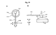
- Fig. 10 shows the steps of forming rubbing traces based on the present implementation mode.
- Fig. 10A is a top view during the formation of rubbing traces.
- Fig. 10B is a lateral view.
- rubbing member 115 is secured to rubbing head 114 on the side facing the side of lens substrate 110 on which the orientation layer is formed.
- Rubbing member 115 is comprised of an elastic material such as a sponge, rubber, or packing, and follows the surface contours of substrate 110.
- Rubbing head 114 is connected to shaft 116.
- shaft 116 is connected to a bidirectional drive element 118 such as a biaxial actuator by means of a support column. That is, in this case, bidirectional drive element 118 can displace rubbing member 115, for example, in a direction y1 parallel to shaft 116, and in a direction x1 that is perpendicular to direction y1 and runs along the surface of rubbing member 115.
- rubbing member 115 is contacted with substrate 110 under a desired pressure f as needed and bidirectional drive element 118 is driven to slide rubbing member 115 freely across substrate 110. That is, in the present mode, it is possible to form rubbing traces based on free curves on the orientation layer of substrate 110.
- the arc-shaped rubbing traces and concentric circular rubbing traces described in the first and second implementation modes above can also be formed.
- a slurry obtained by mixing the above-described abrasives and solvents pure water, oily solvent, or mixture of pure water and additives or the like
- a sheet impregnated with an abrasive such as Al 2 O 3 can be employed in dry processing, or rubbing traces can be formed by feeding pure water or an oil in wet processing.
- the present implementation mode is particularly suited to the use of dichroic dyes that form polarization axes in a direction perpendicular to the rubbing traces formed on the orientation layer.
- dichroic dyes for example, in the course of forming arc-shaped and concentric circular polarization axes, using the center of the arcs as the displacement reference, and radially displacing the rubbing member permits the formation of polarizing layers having polarization axes in arc-shaped or concentric circular directions.
- the polarizing lens 30 shown in Fig. 13 has a distribution of polarization axes 31 that is achieved by orienting and depositing a dichroic dye, having the property of forming polarization axes in a direction perpendicular to the rubbing traces, on an orientation layer in which have been formed rubbing traces tracing curved paths that widen to the right and left from bottom to top about an axis of symmetry in the front vertical direction indicated by dotted line e.
- Fig. 11 is a block diagram of rubbing trace-forming device 100 in the present example.
- jig 110 supporting polarizing lens substrate 160 is positioned opposite rubbing member 120 comprised of an elastic material such as rubber.
- Substrate 160 is secured on jig 110 facing rubbing member 120 with the surface of the orientation layer facing upward.
- Rubbing member 120 is secured to the end of shaft 121.
- the other end of shaft 121 serves as displacement reference C3. That position is connected to shaft 130a of motor 130.
- Control by driver 142 causes the rotation or revolution of motor 130, rotating rubbing member 120 about displacement reference C3 as a center, thereby displacing rubbing member 120 over a arc-shaped path on substrate 160.
- a configuration is also possible in which a central processing unit (CPU) 140 that detects the rotational speed and revolution angle of motor 130 is used to control feedback from motor 130.
- CPU central processing unit
- encoder 141 is connected to motor 130 and driver 142.
- Counter 143 and D/A converter 144 are also connected to driver 142. Each of these is connected to CPU 140.
- the rotational speed and revolution angle of motor 130 are detected by encoder 141, or counter 143 counts the number of rotations and revolution angle of motor 130 as detected by the encoder, which are transmitted to CPU 140.
- CPU 140 sends a control signal to driver 142 via D/A converter 144.
- CPU 140 can also be configured to control slurry feeding element 150.
- the configuration can be such that valve 151 is provided between slurry feeding element 150 and tank 152 in which the slurry is stored, with CPU 140 controlling valve 151.
- CPU 140 opens valve 151, and the slurry that has been stored in tank 152 is fed onto substrate 160 by slurry feeding element 150.
- motor 130 is rotated at some rotational speed, causing rubbing member 120 to revolve as indicated by arrow r3 and slide over the surface of the orientation layer of substrate 160.
- arc-shaped rubbing traces can be formed on the orientation layer on substrate 160.
- linear motion motor 131 can be provided in a direction aligned with the direction of extension of shaft 121 in addition to motor 130. In that case, linear motor 131 can displace displacement reference C3 in the y-axis direction to slide it over the entire surface of substrate 160.
- the positions of rubbing member 120 and jig 110 are desirably set so that the y-axis passes through the geometric center of substrate 160 on jig 110.
- linear motor 132 can be provided that is perpendicular to the direction of displacement of motor 131 to displace displacement reference C3 along the x-axis direction perpendicular to the direction of displacement by motor 131. In that case, not just arc-shaped rubbing traces, but also free curve rubbing traces can be formed.
- the positions of linear motors 131 and 132 can be similarly detected by an encoder, not shown, and feedback control can be conducted by drivers based on the detection signals.
- rotation-use motor 130 can be omitted and various curves can be rubbed, including arcs and closed curves. It is also possible for the shape of the rubbing traces to be controlled by motor 130 and either linear motor 131 or 132.
- revolving rubbing member 120 about displacement reference C3 as a center permits the formation of arc-shaped rubbing traces.
- displacing rubbing member 120 while displacing the position of the displacement reference by linear motors 131 and 132 permits the free formation of rubbing traces in the form of desired curves. Accordingly, it is possible to readily manufacture a polarizing lens provided with polarization axes in various directions of polarization based on use.
- Fig. 12 is a block diagram showing a second example of a rubbing trace-forming device.
- Rubbing trace-forming device 200 in the present example is comprised of jig 210 holding substrate 260 facing downward; rod-shaped or the like shaft 270 supporting jig 210; and support member 271 supporting shaft 270 as indicated by arrow D in such a manner as to allow positional adjustment in the direction of extension thereof.
- Support member 271 can be connected to a raising and lowering drive element, not shown, and a pressure sensor can be connected to jig 210.
- surface plate 220 is disposed facing upward opposite jig 210.
- Motor 230 rotating surface plate 220 is connected to surface plate 220.
- a configuration is possible in which CPU 240 controls feeding of a slurry.
- a configuration is employed in which slurry feeding element 250 is connected to tank 252 through valve 251, and valve 251 is controlled by CPU 240.
- substrate 260 is first secured on jig 210 with the surface of the orientation layer facing the surface plate 220 side.
- the length of shaft 270 holding jig 210 is adjusted to secure substrate 260 at some position relative to surface plate 220, such as the center of rotation of surface plate 220 or a position at a prescribed distance from the center of rotation.
- Slurry stored in tank 252 is fed onto surface plate 220 by slurry feeding element 250 by opening valve 251 based on a signal from CPU 240.
- a raising and lowering drive element and a pressure sensor not shown, lower substrate 260, contacting it against surface plate 220 at a desired pressure.
- the surface of surface plate 220 is comprised of an elastic material such as rubber or packing.
- the contact surface (sliding surface) with substrate 260 is made concave to subject the entire surface of substrate 260 to uniform pressure.
- the use of an elastic material with a concave surface sliding against the orientation layer is preferred.
- Hole 221 is provided in a region containing displacement reference C4, which is the rotational axis, in surface plate 220. A configuration in which this region does not contact substrate 260 can be employed. It is thus possible to obtain a polarizing lens containing a non-polarizing region in the center, as set forth above.
- Surface plate 220 is rotated about displacement reference C4 as a center by motor 230 to form rubbing traces on the orientation layer of substrate 260.
- the contact surface with substrate 260 contains the region of hole 221, concentric circular rubbing traces are formed.
- substrate 260 is fixed at a position away from displacement reference C4 and the contact surface with surface plate 220 does not contain the region of hole 221, arc-shaped rubbing traces are formed.
- by varying the distance of substrate 260 from displacement reference C4 it is possible to freely select the curvature of the arc-shaped rubbing traces.
- the geometric center of substrate 260 is matched with displacement reference C4, rubbing traces are not formed in the region near the geometric center of substrate 260 due to hole 221.
- the rotational speed of motor 230 is detected by encoder 241, and driver 242 conducts feedback control of motor 230 based on the detection signal.
- Counter 243 counts the number of rotations of motor 230 and outputs it to CPU 240.
- the control signal to driver 242 is sent by CPU via D/A converter 244.
- rubbing trace-forming device 200 of the present example can readily form concentric circular rubbing traces and arc-shaped rubbing traces with good control and in a single step by varying the distance of the substrate from the displacement reference position of the surface plate. Accordingly, it is possible to readily manufacture a polarizing lens having polarization axes in various directions.
- a configuration in which the surface plate is secured, motor 231 is connected to jig 210, and motor 231 rotates substrate 260 in the direction of arrow R4 is also possible. It is also possible for a linear motor to be mounted on shaft 270 and for substrate 260 to be displaced in the direction of extension of shaft 270 as indicated by arrow D based on numeric controls.
- the polarization efficiency (Peff) was evaluated in accordance with ISO8980 by obtaining the parallel transmittance (T//) and vertical transmittance (T ⁇ ) and employing the following equation.
- the parallel transmittance and vertical transmittance were measured using a visible-light spectrophotometer and a polarizer.
- Peff % T / / - T ⁇ / T / / + T ⁇ x 100
- a hazemeter HM-150 made by Murakami Color Research Laboratory Co., Ltd. was used to measure the haze value of the polarizing lenses that were produced, and the presence or absence of clouding was determined based on the following evaluation scale.
- the adhesive performance of the polarizing lenses that were prepared was evaluated by immersing the polarizing lenses in boiling water for three hours and then subjecting them to a test under the measurement conditions given below.
- Crosscuts were made at intervals of 1.5 mm to form 100 squares in a cured film, adhesive tape was firmly applied to the crosscut area, and the adhesive tape was rapidly peeled off. The number of the 100 squares of the cured film that peeled off was counted.
- the evaluation scale was as follows.
- Example 1 (Example of forming arc-shaped polarization axes)
- silica sol methanol solvent, solid component 30 weight percent, average primary particle diameter 12 nm
- TEOS tetraethoxysilane
- ⁇ -GPS ⁇ -glycidoxypropyltrimethoxysilane
- orientation layer coating liquid was spin-coated (dispensed at 800 rpm, maintained for 60 s) onto the concave surface of a polyurethane urea lens substrate (trade name Phoenix, made by Hoya Corp., refractive index 1.53, hard coated, 70 mm diameter, base curve 4) and then cured by thermoprocessing for 1 hour at 85°C to prepare an orientation layer (sol-gel film) about 150 nm in thickness.
- a polyurethane urea lens substrate trade name Phoenix, made by Hoya Corp., refractive index 1.53, hard coated, 70 mm diameter, base curve 4
- Rubbing traces were formed with abrasive-containing urethane foam (abrasive: Al 2 O 3 particles 0.1 to 5 micrometer in average diameter; urethane foam: roughly identical in shape to the curvature of the concave surface of a spherical lens) on the orientation layer obtained.
- the processing to form the rubbing traces was conducted for 30 s under a condition of a contact pressure of 50 g/cm 2 .
- the displacement reference of the head was disposed vertically below when the lens would be worn and the rubbing member was swung in an arc shape across the substrate (surface of the orientation layer) to form arc-shaped rubbing traces on the surface of the orientation layer.
- the substrate on which the rubbing traces had been formed was washed with pure water and dried.
- aqueous solution of dichroic dye was spin coated on the surface on which the rubbing traces had been formed (the surface of the orientation layer) to form a polarizing layer.
- the aqueous solution of dye was dispensed at a rotational speed of 300 rpm, maintained for 8 s, dispensed at a rotational speed of 400 rpm, maintained for 45 s, and then dispensed at 1,000 rpm and maintained for 12 s.
- the polarizing lens during this stage exhibited a polarization efficiency of 99 percent and a transmittance of 30.5 percent.
- the dichroic dye employed had the property of forming polarization axes along the rubbing traces, so the distribution of the directions of polarization axes in the polarizing layer that was formed was of the arc shape shown in Fig. 3 .
- an aqueous solution with an iron chloride concentration of 0.15 M, a calcium hydroxide concentration of 0.2 M, and a pH of 3.5 was prepared.
- the lens obtained was immersed for about 30 s in this aqueous solution, after which it was removed and thoroughly washed with pure water. This step rendered the water-soluble dye highly insoluble.
- the lens was immersed for 15 minutes in a 10 weight percent aqueous solution of ⁇ -aminopropyltriethoxysilane, washed three times with pure water, and heat cured for 30 minutes at 85°C. After cooling, the lens was immersed for 30 minutes in a 2 weight percent aqueous solution of ⁇ -glycidoxypropyltrimethoxysilane in air, heat cured for 30 minutes in a 100°C oven, and cooled following curing to form a dye-protecting film (protective layer).
- the lens on which the dye-protecting film had been formed was polished with an abrasive (average particle diameter 0.8 micrometer) and thoroughly washed.
- a coating of UV-curable resin was then applied by spin coating (dispensed at 500 rpm, maintained for 45 s). Following the coating, curing was conducted at a UV irradiation level of 600 mJ/cm 2 with a UV-irradiating apparatus to form a hard coat on the surface on which the protective layer had been formed.
- Example 2 (Example of forming closed-curve polarization axes)
- SiO 2 was vapor deposited with an electron gun under conditions of a substrate temperature of about 50°C and a vacuum of about 10 -5.5 MPa on a substrate in the form of the polyurethane urea lens used in Example 1 to form an orientation layer in the form of an SiO 2 vapor deposition film (thickness 250 nm).
- a substrate temperature of about 50°C
- a vacuum of about 10 -5.5 MPa
- the geometric center of the lens was then positioned on the rotational axis of a surface plate and the surface plate was rotated to form rubbing traces in the form of concentric circles on the orientation layer in the same manner as in the second implementation mode ( Fig. 8 )
- processing was conducted by the same methods as in Example 1.
- the rotational speed of the surface plate was 350 rpm. This yielded a polarizing lens having concentric circular polarization axes, as shown in Fig. 9 .
- a substrate was prepared by conducting vapor deposition with an electron gun under conditions of a substrate temperature of about 50°C and a vacuum of about 10 -5.5 MPa on a substrate in the form of the polyurethane urea lens used in Example 1 to form an orientation layer in the form of an SiO 2 vapor deposition film (thickness 250 nm).
- rubbing traces were formed on this substrate with an abrasive (Al 2 O 3 particles 0.8, 1.3, or 3 micrometers in average particle diameter).
- This processing was conducted in the same manner as in Example 1 with the exceptions of employing a polishing pressure of 50 g/cm 2 and linearly displacing the rubbing pad for 30 s in a uniaxial direction (the direction was fixed at the vertical direction when wearing the lens). Accordingly, polarization axes of the polarizing lens of Comparative Example were linearly aligned in a uniaxial direction in the same manner as the rubbing traces that were formed.
- the polarizing lens of Comparative Example only had horizontal axes of polarization. Thus, it was unable to completely block 45 degree polarized light entering from above at an angle of 45 degrees, and could only block about half of such light.
- the polarizing lenses of Examples 1 and 2 had polarization axes that changed continuously in an axial direction. Thus, they were able to adequately block 45 degree polarized light entering from above at an angle of 45 degrees.
- eyeglasses employing the lenses of Examples 1 and 2 can block light reflecting off of surrounding buildings when the sun is shining diagonally from above, for example, and can eliminate much of the cause of the glare experienced due to reflected light.
- the distribution of the directions of polarization axes in the polarizing layer that is formed is an arc shape, as shown in Fig. 4 .
- the lens is suited to prevent reflection from the surface of water, for example, and when employed as an eyeglass lens for leisure activities and the like near water, it is extremely useful for preventing glare.
Landscapes
- Health & Medical Sciences (AREA)
- Ophthalmology & Optometry (AREA)
- Physics & Mathematics (AREA)
- General Health & Medical Sciences (AREA)
- General Physics & Mathematics (AREA)
- Optics & Photonics (AREA)
- Polarising Elements (AREA)
Claims (12)
- Verfahren zur Herstellung einer polarisierenden Augenglaslinse, umfassend:Bilden einer Orientierungsschicht auf einem Substrat;Verschieben eines Reibelements über die Orientierungsschicht in einem Zustand des Kontakts mit der Orlentierungsschicht, um gekrümmte Reibspuren auf einer Oberfläche der Orientierungsschicht zu bilden;Bilden einer polarisierenden Schicht durch Ablagern und Orientieren eines dichroitischen Farbstoffs auf der Orientierungsschicht; undAusführen einer Behandlung bei der polarisierenden Schicht zur Immobilisierung des dichroitischen Farbstoffs in der polarisierenden Schicht.
- Verfahren zur Herstellung einer polarisierenden Augenglaslinse nach Anspruch 1, wobei die gekrümmten Reibspuren gebildet werden durch Fixieren des Reibelements oder des Substrats und Verschieben des anderen der beiden unter Verwendung einer Verlagerungsreferenz an einer gegebenen Position als ein Drehzentrum mit dem Reibelement in einem Zustand des Kontakts mit der Orientierungsschicht.
- Verfahren zur Herstellung einer polarisierenden Augenglaslinse nach Anspruch 2, wobei das Reibelement oder das Substrat verschoben wird, während es eine bogenförmige Spur zieht, unter Verwendung der Verlagerungsreferenz als Drehzentrum.
- Verfahren zur Herstellung einer polarisierenden Augenglaslinse nach Anspruch 2, wobei das Reibelement oder das Substrat verschoben wird, während es sich um die Verlagerungsreferenz als Drehzentrum dreht.
- Verfahren zur Herstellung einer polarisierenden Augenglaslinse nach einem der Ansprüche 2 bis 4, wobei die Verlagerungsreferenz vertikal unter einem geometrischen Zentrum des Substrats im Tragezustand der Linse positioniert ist.
- Verfahren zur Herstellung einer polarisierenden Augenglaslinse nach einem der Ansprüche 2 bis 4, wobei die Verlagerungsrefierenz vertikal über einem geometrischen Zentrum des Substrats im Tragezustand der Linse positioniert ist.
- Verfahren zur Herstellung einer polarisierenden Augenglaslinse nach Anspruch 5 oder 6, wobei die Verlagerungsreferenz auf einer vertikalen Linie positioniert ist, die durch das geometrische Zentrum des Substrats verläuft.
- Verfahren zur Herstellung einer polarisierenden Augenglaslinse nach einem der Ansprüche 1 bis 7, wobei ein Nichtkontaktbereich, in welchem kein Kontakt zwischen dem Reibelement und der Orientierungsschicht besteht, in einer Region vorgesehen ist, die ein geometrisches Zentrum des Substrats enthält.
- Verfahren zur Herstellung einer polarisierenden Augenglaslinse nach Anspruch 8, wobei der Nichtkontaktbereich einen Außendurchmesser von größer oder gleich 4mm jedoch kleiner oder gleich 15mm hat.
- Verfahren zur Herstellung einer polarisierenden Augenglaslinse nach Anspruch 1, wobei die gekrümmten Reibspuren gebildet werden, indem entweder das Reibelement oder das Substrat relativ in zwei oder mehr verschiedenen Richtungen durch Verschieben verlagert werden, wobei sich das Reibelement in einem Zustand des Kontakts mit der Orientierungsschicht befindet.
- Verfahren zur Herstellung einer polarisierenden Augenglaslinse nach einem der Ansprüche 1 bis 10, wobei die Orientierungsschicht in der Form eines Sol-Gel-Films gebildet wird.
- Verfahren zur Herstellung einer polarisierenden Augenglaslinse nach einem der Ansprüche 1 bis 11, wobei das Reibelement ein elastisches Element mit einer konkaven Oberfläche ist, die gegen die Orientierungsschicht verschoben wird.
Applications Claiming Priority (2)
| Application Number | Priority Date | Filing Date | Title |
|---|---|---|---|
| JP2009182885 | 2009-08-05 | ||
| JP2010166738A JP2011053661A (ja) | 2009-08-05 | 2010-07-26 | 眼鏡用偏光レンズの製造方法 |
Publications (2)
| Publication Number | Publication Date |
|---|---|
| EP2284599A1 EP2284599A1 (de) | 2011-02-16 |
| EP2284599B1 true EP2284599B1 (de) | 2012-05-23 |
Family
ID=43037652
Family Applications (1)
| Application Number | Title | Priority Date | Filing Date |
|---|---|---|---|
| EP10172025A Not-in-force EP2284599B1 (de) | 2009-08-05 | 2010-08-05 | Methode zum Herstellen einer polarisierenden Brillenlinse |
Country Status (3)
| Country | Link |
|---|---|
| US (1) | US8414802B2 (de) |
| EP (1) | EP2284599B1 (de) |
| JP (1) | JP2011053661A (de) |
Families Citing this family (4)
| Publication number | Priority date | Publication date | Assignee | Title |
|---|---|---|---|---|
| US9427818B2 (en) * | 2014-01-20 | 2016-08-30 | Taiwan Semiconductor Manufacturing Company, Ltd. | Semiconductor processing boat design with pressure sensor |
| CN105807359B (zh) * | 2016-05-30 | 2017-04-05 | 京东方科技集团股份有限公司 | 线偏光层、圆偏光层、柔性显示装置及其制备方法 |
| CN107399037B (zh) * | 2017-07-24 | 2023-09-01 | 临海市锦铮机械有限公司 | 全自动光控树脂镜片浇注机 |
| KR102787980B1 (ko) * | 2022-06-09 | 2025-03-31 | 한국과학기술원 | 터치스크린 디스플레이용 안티글레어 처리 방법 및 그를 위한 시스템 |
Family Cites Families (10)
| Publication number | Priority date | Publication date | Assignee | Title |
|---|---|---|---|---|
| US2398506A (en) * | 1940-12-24 | 1946-04-16 | Polaroid Corp | Light polarizer and method of manufacture |
| US2400877A (en) * | 1941-03-21 | 1946-05-28 | John F Dreyer | Optical device and method and manufacture thereof |
| US2359456A (en) * | 1942-06-03 | 1944-10-03 | Polaroid Corp | Antiglare device |
| US2603129A (en) * | 1947-05-01 | 1952-07-15 | John F Dreyer | Dial indicator having polarizing elements |
| US2577620A (en) * | 1948-05-12 | 1951-12-04 | American Optical Corp | Light polarizer and process of making the same |
| FR2531235B1 (fr) * | 1982-07-27 | 1985-11-15 | Corning Glass Works | Verres stratifies transparents polarisants et leur procede d'obtention |
| US6245399B1 (en) | 1998-10-14 | 2001-06-12 | 3M Innovative Properties Company | Guest-host polarizers |
| KR101237182B1 (ko) | 2004-12-21 | 2013-03-04 | 코닝 인코포레이티드 | 편광 제품 및 이의 제조방법 |
| FR2891375B1 (fr) * | 2005-09-29 | 2008-02-15 | Essilor Int | Lentille ophtalmique polarisante adaptee au comportement oeil/tete d'un porteur. |
| US20090274853A1 (en) * | 2008-03-31 | 2009-11-05 | Fujifilm Corporation | Dichroic dye composition |
-
2010
- 2010-07-26 JP JP2010166738A patent/JP2011053661A/ja active Pending
- 2010-08-04 US US12/850,192 patent/US8414802B2/en not_active Expired - Fee Related
- 2010-08-05 EP EP10172025A patent/EP2284599B1/de not_active Not-in-force
Also Published As
| Publication number | Publication date |
|---|---|
| US8414802B2 (en) | 2013-04-09 |
| EP2284599A1 (de) | 2011-02-16 |
| US20110030152A1 (en) | 2011-02-10 |
| JP2011053661A (ja) | 2011-03-17 |
Similar Documents
| Publication | Publication Date | Title |
|---|---|---|
| EP2284601B1 (de) | Polarisierende Linse | |
| US7922847B2 (en) | Light polarizing products and method of making same | |
| EP1674898B1 (de) | Lichtpolarisierende Produkte und Verfahren zur deren Herstellung | |
| EP2415587A1 (de) | Verfahren zur herstellung einer polarisierten linse, polarisierte linse und linsenherstellungsverfahren | |
| US9116301B2 (en) | Durable light-polarizing articles and method of making the same | |
| JP5555688B2 (ja) | 偏光レンズの製造方法 | |
| US8414802B2 (en) | Method of manufacturing polarizing eyeglass lens | |
| EP2284600B1 (de) | Polarisierende Linse | |
| JP2015121805A (ja) | 偏光素子及び偏光レンズの製造方法 | |
| JP2012048113A (ja) | 偏光レンズ |
Legal Events
| Date | Code | Title | Description |
|---|---|---|---|
| PUAI | Public reference made under article 153(3) epc to a published international application that has entered the european phase |
Free format text: ORIGINAL CODE: 0009012 |
|
| AK | Designated contracting states |
Kind code of ref document: A1 Designated state(s): AL AT BE BG CH CY CZ DE DK EE ES FI FR GB GR HR HU IE IS IT LI LT LU LV MC MK MT NL NO PL PT RO SE SI SK SM TR |
|
| AX | Request for extension of the european patent |
Extension state: BA ME RS |
|
| 17P | Request for examination filed |
Effective date: 20110707 |
|
| GRAP | Despatch of communication of intention to grant a patent |
Free format text: ORIGINAL CODE: EPIDOSNIGR1 |
|
| GRAS | Grant fee paid |
Free format text: ORIGINAL CODE: EPIDOSNIGR3 |
|
| GRAA | (expected) grant |
Free format text: ORIGINAL CODE: 0009210 |
|
| RAP1 | Party data changed (applicant data changed or rights of an application transferred) |
Owner name: HOYA CORPORATION |
|
| AK | Designated contracting states |
Kind code of ref document: B1 Designated state(s): AL AT BE BG CH CY CZ DE DK EE ES FI FR GB GR HR HU IE IS IT LI LT LU LV MC MK MT NL NO PL PT RO SE SI SK SM TR |
|
| REG | Reference to a national code |
Ref country code: GB Ref legal event code: FG4D |
|
| REG | Reference to a national code |
Ref country code: CH Ref legal event code: EP |
|
| REG | Reference to a national code |
Ref country code: AT Ref legal event code: REF Ref document number: 559333 Country of ref document: AT Kind code of ref document: T Effective date: 20120615 |
|
| REG | Reference to a national code |
Ref country code: IE Ref legal event code: FG4D |
|
| REG | Reference to a national code |
Ref country code: DE Ref legal event code: R096 Ref document number: 602010001646 Country of ref document: DE Effective date: 20120719 |
|
| REG | Reference to a national code |
Ref country code: NL Ref legal event code: VDEP Effective date: 20120523 |
|
| REG | Reference to a national code |
Ref country code: LT Ref legal event code: MG4D Effective date: 20120523 |
|
| PG25 | Lapsed in a contracting state [announced via postgrant information from national office to epo] |
Ref country code: IS Free format text: LAPSE BECAUSE OF FAILURE TO SUBMIT A TRANSLATION OF THE DESCRIPTION OR TO PAY THE FEE WITHIN THE PRESCRIBED TIME-LIMIT Effective date: 20120923 Ref country code: CY Free format text: LAPSE BECAUSE OF FAILURE TO SUBMIT A TRANSLATION OF THE DESCRIPTION OR TO PAY THE FEE WITHIN THE PRESCRIBED TIME-LIMIT Effective date: 20120523 Ref country code: NO Free format text: LAPSE BECAUSE OF FAILURE TO SUBMIT A TRANSLATION OF THE DESCRIPTION OR TO PAY THE FEE WITHIN THE PRESCRIBED TIME-LIMIT Effective date: 20120823 Ref country code: FI Free format text: LAPSE BECAUSE OF FAILURE TO SUBMIT A TRANSLATION OF THE DESCRIPTION OR TO PAY THE FEE WITHIN THE PRESCRIBED TIME-LIMIT Effective date: 20120523 Ref country code: LT Free format text: LAPSE BECAUSE OF FAILURE TO SUBMIT A TRANSLATION OF THE DESCRIPTION OR TO PAY THE FEE WITHIN THE PRESCRIBED TIME-LIMIT Effective date: 20120523 Ref country code: SE Free format text: LAPSE BECAUSE OF FAILURE TO SUBMIT A TRANSLATION OF THE DESCRIPTION OR TO PAY THE FEE WITHIN THE PRESCRIBED TIME-LIMIT Effective date: 20120523 |
|
| REG | Reference to a national code |
Ref country code: AT Ref legal event code: MK05 Ref document number: 559333 Country of ref document: AT Kind code of ref document: T Effective date: 20120523 |
|
| PG25 | Lapsed in a contracting state [announced via postgrant information from national office to epo] |
Ref country code: LV Free format text: LAPSE BECAUSE OF FAILURE TO SUBMIT A TRANSLATION OF THE DESCRIPTION OR TO PAY THE FEE WITHIN THE PRESCRIBED TIME-LIMIT Effective date: 20120523 Ref country code: PT Free format text: LAPSE BECAUSE OF FAILURE TO SUBMIT A TRANSLATION OF THE DESCRIPTION OR TO PAY THE FEE WITHIN THE PRESCRIBED TIME-LIMIT Effective date: 20120924 Ref country code: SI Free format text: LAPSE BECAUSE OF FAILURE TO SUBMIT A TRANSLATION OF THE DESCRIPTION OR TO PAY THE FEE WITHIN THE PRESCRIBED TIME-LIMIT Effective date: 20120523 Ref country code: HR Free format text: LAPSE BECAUSE OF FAILURE TO SUBMIT A TRANSLATION OF THE DESCRIPTION OR TO PAY THE FEE WITHIN THE PRESCRIBED TIME-LIMIT Effective date: 20120523 Ref country code: GR Free format text: LAPSE BECAUSE OF FAILURE TO SUBMIT A TRANSLATION OF THE DESCRIPTION OR TO PAY THE FEE WITHIN THE PRESCRIBED TIME-LIMIT Effective date: 20120824 |
|
| PG25 | Lapsed in a contracting state [announced via postgrant information from national office to epo] |
Ref country code: BE Free format text: LAPSE BECAUSE OF FAILURE TO SUBMIT A TRANSLATION OF THE DESCRIPTION OR TO PAY THE FEE WITHIN THE PRESCRIBED TIME-LIMIT Effective date: 20120523 |
|
| PGFP | Annual fee paid to national office [announced via postgrant information from national office to epo] |
Ref country code: DE Payment date: 20120808 Year of fee payment: 3 |
|
| PG25 | Lapsed in a contracting state [announced via postgrant information from national office to epo] |
Ref country code: AT Free format text: LAPSE BECAUSE OF FAILURE TO SUBMIT A TRANSLATION OF THE DESCRIPTION OR TO PAY THE FEE WITHIN THE PRESCRIBED TIME-LIMIT Effective date: 20120523 Ref country code: DK Free format text: LAPSE BECAUSE OF FAILURE TO SUBMIT A TRANSLATION OF THE DESCRIPTION OR TO PAY THE FEE WITHIN THE PRESCRIBED TIME-LIMIT Effective date: 20120523 Ref country code: NL Free format text: LAPSE BECAUSE OF FAILURE TO SUBMIT A TRANSLATION OF THE DESCRIPTION OR TO PAY THE FEE WITHIN THE PRESCRIBED TIME-LIMIT Effective date: 20120523 Ref country code: CZ Free format text: LAPSE BECAUSE OF FAILURE TO SUBMIT A TRANSLATION OF THE DESCRIPTION OR TO PAY THE FEE WITHIN THE PRESCRIBED TIME-LIMIT Effective date: 20120523 Ref country code: EE Free format text: LAPSE BECAUSE OF FAILURE TO SUBMIT A TRANSLATION OF THE DESCRIPTION OR TO PAY THE FEE WITHIN THE PRESCRIBED TIME-LIMIT Effective date: 20120523 Ref country code: RO Free format text: LAPSE BECAUSE OF FAILURE TO SUBMIT A TRANSLATION OF THE DESCRIPTION OR TO PAY THE FEE WITHIN THE PRESCRIBED TIME-LIMIT Effective date: 20120523 Ref country code: SK Free format text: LAPSE BECAUSE OF FAILURE TO SUBMIT A TRANSLATION OF THE DESCRIPTION OR TO PAY THE FEE WITHIN THE PRESCRIBED TIME-LIMIT Effective date: 20120523 |
|
| PG25 | Lapsed in a contracting state [announced via postgrant information from national office to epo] |
Ref country code: IT Free format text: LAPSE BECAUSE OF FAILURE TO SUBMIT A TRANSLATION OF THE DESCRIPTION OR TO PAY THE FEE WITHIN THE PRESCRIBED TIME-LIMIT Effective date: 20120523 Ref country code: PL Free format text: LAPSE BECAUSE OF FAILURE TO SUBMIT A TRANSLATION OF THE DESCRIPTION OR TO PAY THE FEE WITHIN THE PRESCRIBED TIME-LIMIT Effective date: 20120523 |
|
| PG25 | Lapsed in a contracting state [announced via postgrant information from national office to epo] |
Ref country code: MC Free format text: LAPSE BECAUSE OF NON-PAYMENT OF DUE FEES Effective date: 20120831 |
|
| PLBE | No opposition filed within time limit |
Free format text: ORIGINAL CODE: 0009261 |
|
| STAA | Information on the status of an ep patent application or granted ep patent |
Free format text: STATUS: NO OPPOSITION FILED WITHIN TIME LIMIT |
|
| PG25 | Lapsed in a contracting state [announced via postgrant information from national office to epo] |
Ref country code: ES Free format text: LAPSE BECAUSE OF FAILURE TO SUBMIT A TRANSLATION OF THE DESCRIPTION OR TO PAY THE FEE WITHIN THE PRESCRIBED TIME-LIMIT Effective date: 20120903 |
|
| 26N | No opposition filed |
Effective date: 20130226 |
|
| REG | Reference to a national code |
Ref country code: FR Ref legal event code: ST Effective date: 20130430 |
|
| REG | Reference to a national code |
Ref country code: IE Ref legal event code: MM4A |
|
| REG | Reference to a national code |
Ref country code: DE Ref legal event code: R097 Ref document number: 602010001646 Country of ref document: DE Effective date: 20130226 |
|
| PG25 | Lapsed in a contracting state [announced via postgrant information from national office to epo] |
Ref country code: IE Free format text: LAPSE BECAUSE OF NON-PAYMENT OF DUE FEES Effective date: 20120805 Ref country code: BG Free format text: LAPSE BECAUSE OF FAILURE TO SUBMIT A TRANSLATION OF THE DESCRIPTION OR TO PAY THE FEE WITHIN THE PRESCRIBED TIME-LIMIT Effective date: 20120823 |
|
| PG25 | Lapsed in a contracting state [announced via postgrant information from national office to epo] |
Ref country code: FR Free format text: LAPSE BECAUSE OF NON-PAYMENT OF DUE FEES Effective date: 20120831 |
|
| PG25 | Lapsed in a contracting state [announced via postgrant information from national office to epo] |
Ref country code: MT Free format text: LAPSE BECAUSE OF FAILURE TO SUBMIT A TRANSLATION OF THE DESCRIPTION OR TO PAY THE FEE WITHIN THE PRESCRIBED TIME-LIMIT Effective date: 20120523 Ref country code: AL Free format text: LAPSE BECAUSE OF FAILURE TO SUBMIT A TRANSLATION OF THE DESCRIPTION OR TO PAY THE FEE WITHIN THE PRESCRIBED TIME-LIMIT Effective date: 20120523 |
|
| PG25 | Lapsed in a contracting state [announced via postgrant information from national office to epo] |
Ref country code: TR Free format text: LAPSE BECAUSE OF FAILURE TO SUBMIT A TRANSLATION OF THE DESCRIPTION OR TO PAY THE FEE WITHIN THE PRESCRIBED TIME-LIMIT Effective date: 20120523 Ref country code: DE Free format text: LAPSE BECAUSE OF NON-PAYMENT OF DUE FEES Effective date: 20140301 |
|
| REG | Reference to a national code |
Ref country code: DE Ref legal event code: R119 Ref document number: 602010001646 Country of ref document: DE Effective date: 20140301 |
|
| PG25 | Lapsed in a contracting state [announced via postgrant information from national office to epo] |
Ref country code: LU Free format text: LAPSE BECAUSE OF NON-PAYMENT OF DUE FEES Effective date: 20120805 Ref country code: SM Free format text: LAPSE BECAUSE OF FAILURE TO SUBMIT A TRANSLATION OF THE DESCRIPTION OR TO PAY THE FEE WITHIN THE PRESCRIBED TIME-LIMIT Effective date: 20120523 |
|
| PG25 | Lapsed in a contracting state [announced via postgrant information from national office to epo] |
Ref country code: HU Free format text: LAPSE BECAUSE OF FAILURE TO SUBMIT A TRANSLATION OF THE DESCRIPTION OR TO PAY THE FEE WITHIN THE PRESCRIBED TIME-LIMIT Effective date: 20100805 |
|
| REG | Reference to a national code |
Ref country code: CH Ref legal event code: PL |
|
| GBPC | Gb: european patent ceased through non-payment of renewal fee |
Effective date: 20140805 |
|
| PG25 | Lapsed in a contracting state [announced via postgrant information from national office to epo] |
Ref country code: LI Free format text: LAPSE BECAUSE OF NON-PAYMENT OF DUE FEES Effective date: 20140831 Ref country code: CH Free format text: LAPSE BECAUSE OF NON-PAYMENT OF DUE FEES Effective date: 20140831 |
|
| PG25 | Lapsed in a contracting state [announced via postgrant information from national office to epo] |
Ref country code: GB Free format text: LAPSE BECAUSE OF NON-PAYMENT OF DUE FEES Effective date: 20140805 Ref country code: MK Free format text: LAPSE BECAUSE OF FAILURE TO SUBMIT A TRANSLATION OF THE DESCRIPTION OR TO PAY THE FEE WITHIN THE PRESCRIBED TIME-LIMIT Effective date: 20120523 |