EP2284824A2 - Lichtemittierende Anzeigevorrichtung und Verfahren zum Betreiben der lichtemittierenden Anzeigevorrichtung - Google Patents
Lichtemittierende Anzeigevorrichtung und Verfahren zum Betreiben der lichtemittierenden Anzeigevorrichtung Download PDFInfo
- Publication number
- EP2284824A2 EP2284824A2 EP10168048A EP10168048A EP2284824A2 EP 2284824 A2 EP2284824 A2 EP 2284824A2 EP 10168048 A EP10168048 A EP 10168048A EP 10168048 A EP10168048 A EP 10168048A EP 2284824 A2 EP2284824 A2 EP 2284824A2
- Authority
- EP
- European Patent Office
- Prior art keywords
- light emitting
- emitting display
- panel
- self light
- display panel
- Prior art date
- Legal status (The legal status is an assumption and is not a legal conclusion. Google has not performed a legal analysis and makes no representation as to the accuracy of the status listed.)
- Withdrawn
Links
Images








Classifications
-
- G—PHYSICS
- G09—EDUCATION; CRYPTOGRAPHY; DISPLAY; ADVERTISING; SEALS
- G09G—ARRANGEMENTS OR CIRCUITS FOR CONTROL OF INDICATING DEVICES USING STATIC MEANS TO PRESENT VARIABLE INFORMATION
- G09G3/00—Control arrangements or circuits, of interest only in connection with visual indicators other than cathode-ray tubes
- G09G3/20—Control arrangements or circuits, of interest only in connection with visual indicators other than cathode-ray tubes for presentation of an assembly of a number of characters, e.g. a page, by composing the assembly by combination of individual elements arranged in a matrix no fixed position being assigned to or needed to be assigned to the individual characters or partial characters
- G09G3/22—Control arrangements or circuits, of interest only in connection with visual indicators other than cathode-ray tubes for presentation of an assembly of a number of characters, e.g. a page, by composing the assembly by combination of individual elements arranged in a matrix no fixed position being assigned to or needed to be assigned to the individual characters or partial characters using controlled light sources
- G09G3/30—Control arrangements or circuits, of interest only in connection with visual indicators other than cathode-ray tubes for presentation of an assembly of a number of characters, e.g. a page, by composing the assembly by combination of individual elements arranged in a matrix no fixed position being assigned to or needed to be assigned to the individual characters or partial characters using controlled light sources using electroluminescent panels
- G09G3/32—Control arrangements or circuits, of interest only in connection with visual indicators other than cathode-ray tubes for presentation of an assembly of a number of characters, e.g. a page, by composing the assembly by combination of individual elements arranged in a matrix no fixed position being assigned to or needed to be assigned to the individual characters or partial characters using controlled light sources using electroluminescent panels semiconductive, e.g. using light-emitting diodes [LED]
- G09G3/3208—Control arrangements or circuits, of interest only in connection with visual indicators other than cathode-ray tubes for presentation of an assembly of a number of characters, e.g. a page, by composing the assembly by combination of individual elements arranged in a matrix no fixed position being assigned to or needed to be assigned to the individual characters or partial characters using controlled light sources using electroluminescent panels semiconductive, e.g. using light-emitting diodes [LED] organic, e.g. using organic light-emitting diodes [OLED]
-
- G—PHYSICS
- G09—EDUCATION; CRYPTOGRAPHY; DISPLAY; ADVERTISING; SEALS
- G09G—ARRANGEMENTS OR CIRCUITS FOR CONTROL OF INDICATING DEVICES USING STATIC MEANS TO PRESENT VARIABLE INFORMATION
- G09G2320/00—Control of display operating conditions
- G09G2320/02—Improving the quality of display appearance
- G09G2320/0271—Adjustment of the gradation levels within the range of the gradation scale, e.g. by redistribution or clipping
- G09G2320/0276—Adjustment of the gradation levels within the range of the gradation scale, e.g. by redistribution or clipping for the purpose of adaptation to the characteristics of a display device, i.e. gamma correction
-
- G—PHYSICS
- G09—EDUCATION; CRYPTOGRAPHY; DISPLAY; ADVERTISING; SEALS
- G09G—ARRANGEMENTS OR CIRCUITS FOR CONTROL OF INDICATING DEVICES USING STATIC MEANS TO PRESENT VARIABLE INFORMATION
- G09G2320/00—Control of display operating conditions
- G09G2320/06—Adjustment of display parameters
- G09G2320/0626—Adjustment of display parameters for control of overall brightness
- G09G2320/0633—Adjustment of display parameters for control of overall brightness by amplitude modulation of the brightness of the illumination source
-
- G—PHYSICS
- G09—EDUCATION; CRYPTOGRAPHY; DISPLAY; ADVERTISING; SEALS
- G09G—ARRANGEMENTS OR CIRCUITS FOR CONTROL OF INDICATING DEVICES USING STATIC MEANS TO PRESENT VARIABLE INFORMATION
- G09G2360/00—Aspects of the architecture of display systems
- G09G2360/14—Detecting light within display terminals, e.g. using a single or a plurality of photosensors
- G09G2360/144—Detecting light within display terminals, e.g. using a single or a plurality of photosensors the light being ambient light
-
- G—PHYSICS
- G09—EDUCATION; CRYPTOGRAPHY; DISPLAY; ADVERTISING; SEALS
- G09G—ARRANGEMENTS OR CIRCUITS FOR CONTROL OF INDICATING DEVICES USING STATIC MEANS TO PRESENT VARIABLE INFORMATION
- G09G3/00—Control arrangements or circuits, of interest only in connection with visual indicators other than cathode-ray tubes
- G09G3/20—Control arrangements or circuits, of interest only in connection with visual indicators other than cathode-ray tubes for presentation of an assembly of a number of characters, e.g. a page, by composing the assembly by combination of individual elements arranged in a matrix no fixed position being assigned to or needed to be assigned to the individual characters or partial characters
- G09G3/22—Control arrangements or circuits, of interest only in connection with visual indicators other than cathode-ray tubes for presentation of an assembly of a number of characters, e.g. a page, by composing the assembly by combination of individual elements arranged in a matrix no fixed position being assigned to or needed to be assigned to the individual characters or partial characters using controlled light sources
- G09G3/30—Control arrangements or circuits, of interest only in connection with visual indicators other than cathode-ray tubes for presentation of an assembly of a number of characters, e.g. a page, by composing the assembly by combination of individual elements arranged in a matrix no fixed position being assigned to or needed to be assigned to the individual characters or partial characters using controlled light sources using electroluminescent panels
- G09G3/32—Control arrangements or circuits, of interest only in connection with visual indicators other than cathode-ray tubes for presentation of an assembly of a number of characters, e.g. a page, by composing the assembly by combination of individual elements arranged in a matrix no fixed position being assigned to or needed to be assigned to the individual characters or partial characters using controlled light sources using electroluminescent panels semiconductive, e.g. using light-emitting diodes [LED]
- G09G3/3208—Control arrangements or circuits, of interest only in connection with visual indicators other than cathode-ray tubes for presentation of an assembly of a number of characters, e.g. a page, by composing the assembly by combination of individual elements arranged in a matrix no fixed position being assigned to or needed to be assigned to the individual characters or partial characters using controlled light sources using electroluminescent panels semiconductive, e.g. using light-emitting diodes [LED] organic, e.g. using organic light-emitting diodes [OLED]
- G09G3/3225—Control arrangements or circuits, of interest only in connection with visual indicators other than cathode-ray tubes for presentation of an assembly of a number of characters, e.g. a page, by composing the assembly by combination of individual elements arranged in a matrix no fixed position being assigned to or needed to be assigned to the individual characters or partial characters using controlled light sources using electroluminescent panels semiconductive, e.g. using light-emitting diodes [LED] organic, e.g. using organic light-emitting diodes [OLED] using an active matrix
Definitions
- the present invention relates to a self light emitting display device and a method for driving self light emitting display device.
- the brightness of a screen displayed by the device is set high according to the home use environment.
- the brightness of the screen of a studio video monitor, a master monitor, a photograph monitor for checking photographs, and the like is set low because reproduction quality is more important than the brightness of a video image.
- a reference brightness of the device is set high, and a certain gain is set on a video signal in a dark environment to realize the method. For example, when the brightness can be one-half of a maximum brightness corresponding to a maximum input "1", the gain is set to "0.5". However, in this case, a color resolution of the input signal decreases to one-half.
- a backlight is controlled to control the brightness, and gain need not be applied to the input signal.
- a gain needs to be applied to the input signal so as to change the brightness of the screen.
- applying a gain to the input signal decreases a color resolution of a video image.
- Japanese Unexamined Patent Application Publication No. 2005-208241 discloses that only the brightness can be controlled without decreasing bit depth by independently controlling R, G, and B. However, in the technique of Japanese Unexamined Patent Application Publication No. 2005-208241 , an issue occurs in intermediate gradation expression capability in a device having a gamma unique to the display.
- a self light emitting display device including an active matrix drive type self light emitting display panel, a necessary brightness calculation unit which calculates a necessary maximum brightness that is necessary for light emission of the self light emitting display panel based on a user setting, a circumference environment, or a video signal, a panel driver which drives the self light emitting display panel by changing a maximum voltage supplied to the self light emitting display panel according to the necessary maximum brightness, a storage unit which holds data related to a reverse gamma characteristic that is opposite to a gamma characteristic between an amount of light emitted from the self light emitting display panel and a voltage supplied from the panel driver to the self light emitting display panel, and a panel gamma generation unit which generates an output signal to the panel driver based on the reverse gamma characteristic by changing an applicable range of the reverse gamma characteristic according to the necessary maximum brightness while maintaining the same gradations as those when the self light emitting display panel emits light at a displayable maximum brightness.
- the number of gradations of a signal input in the applicable range of the reverse gamma characteristic may be the same as those when the self light emitting display panel emits light at a displayable maximum brightness regardless of a value of the necessary maximum brightness.
- the applicable range of the reverse gamma characteristic which is changed according to the necessary maximum brightness may be determined based on the maximum voltage.
- a method for driving a self light emitting display device including the steps of calculating a necessary maximum brightness that is necessary for light emission of an active matrix drive type self light emitting display panel based on a user setting, a circumference environment, or a video signal, by a necessary brightness calculation unit, driving the self light emitting display panel by changing a maximum voltage supplied to the self light emitting display panel according to the necessary maximum brightness, by a panel driver, holding data related to a reverse gamma characteristic that is opposite to a gamma characteristic between an amount of light emitted from the self light emitting display panel and a voltage supplied from the panel driver to the self light emitting display panel, by a storage unit, generating an output signal to the panel driver based on the reverse gamma characteristic by changing an applicable range of the reverse gamma characteristic according to the necessary maximum brightness while maintaining the same gradations as those when the self light emitting display panel emits light at a displayable maximum brightness, by a panel
- FIG. 1 is a block diagram showing an organic EL display device 100 according to the embodiment.
- the organic EL display device 100 includes a CPU 102, a memory 104, a linear gamma generation unit 105, a panel gamma generation unit 106, a necessary brightness calculation unit 108, a panel driver 110, and an OLED panel 120.
- a video input signal is input into the organic EL display device 100, and the organic EL display device 100 displays a video image on the OLED panel 120 based on the video input signal.
- the CPU 102 controls each functional block included in the organic EL display device 100.
- the memory 104 holds, for example, brightness information related to a displayable maximum brightness that can be represented by the organic EL display device 100.
- the video input signal is input into the linear gamma generation unit 105, and the linear gamma generation unit 105 converts the video input signal and outputs a signal A.
- FIG. 2 is a graph showing the relationship between the strength of light and the video input signal input into the organic EL display device 100.
- the memory 104 holds data having a characteristic opposite to the gamma characteristic of the relationship between the video input signal input into the organic EL display device 100 and the strength of light, for example, as a look-up table (LUT).
- the amount of data in the look-up table held by the memory 104 can be arbitrarily determined according to a curve characteristic or the like.
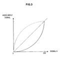
- the linear gamma generation unit 105 reads the LUT and performs interpolation processing to generate curve data as shown in FIG. 3 having a characteristic opposite to the gamma characteristic of the relationship between the video input signal input into the organic EL display device 100 and the strength of light.
- FIG. 3 is a graph showing a relationship between the video input signal and the signal A.
- the linear gamma generation unit 105 converts the video input signal by using the curve data shown in FIG. 3 , and outputs the signal A. Based on this, the strength of light and the signal A have a linear relationship as shown in FIG. 4.
- FIG. 4 is a graph showing the relationship between the strength of light and the signal A input into the panel gamma generation unit 106.
- the signal A output from the linear gamma generation unit 105 is input into the panel gamma generation unit 106.
- the panel gamma generation unit 106 converts the signal A and outputs a signal B related to a value of panel drive voltage.
- the memory 104 is an example of a storage unit, and holds data having the characteristic opposite to the gamma characteristic (reverse gamma characteristic) of the OLED panel 120 as a look-up table (LUT).
- LUT look-up table
- the OLED (Organic light-emitting diode) panel 120 is an example of an active matrix drive type self light emitting display panel.
- the OLED panel 120 has a gamma characteristic as shown in FIG. 5.
- FIG. 5 is a graph showing a relationship between an amount of light emitted from the OLED panel 120 and an input voltage.
- the gamma characteristic of the OLED panel 120 is represented by brightness of light (amount of emitting light) emitted from the OLED panel 120 and a panel drive voltage input into the OLED panel 120 from the panel driver 110.
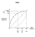
- the data having the characteristic opposite to the gamma characteristic of the OLED panel 120 is represented by a curve as shown in FIG. 6 .
- the panel gamma generation unit 106 reads the LUT and performs interpolation processing to generate data having the characteristic opposite to the gamma characteristic of the OLED panel 120 as shown in FIG. 6.
- FIG 6 is a graph showing a relationship between an output signal (signal B) from the panel gamma generation unit 106 and an input signal (signal A) to the panel gamma generation unit 106.
- the panel gamma generation unit 106 converts the input signal A by using the curve data shown in FIG. 6 , and outputs the signal B related to a voltage value.
- the curve data used when the panel gamma generation unit 106 converts the signal is changed according to the necessary maximum brightness. How to change the curve data will be described below.
- the amount of data in the look-up table held by the memory 104 can be arbitrarily determined according to a curve characteristic or the like.
- the memory 104 holds data of arbitrary points as represented by the points on the curve in FIG. 6 as table data shown in FIG. 7.
- FIG. 7 is an explanatory diagram illustrating the look-up table (LUT) of the data having the characteristic opposite to the gamma characteristic of the OLED panel 120.
- the panel gamma generation unit 106 interpolates the LUT, so that the panel gamma generation unit 106 can output appropriate value even when a value not included in the table data is input.
- the interpolation of the LUT is performed by a method used in general, such as linear interpolation.
- the signal B output from the panel gamma generation unit 106 is input into the panel driver 110.
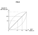
- the signal A input into the panel gamma generation unit 106 and the brightness of the light (amount of the emitting light) emitted from the OLED panel 120 have a linear relationship as shown in FIG. 8.
- FIG. 8 is a graph showing the relationship between the amount of light emitted from the OLED panel 120 and the signal A.
- the necessary brightness calculation unit 108 calculates a maximum brightness necessary for light emission of the OLED panel 120 to emit light based on a user setting, a detection result of circumference environment, an analysis result of the video signal, and the like. For example, when the organic EL display device 100 can be used as a home display, the brightness of the screen displayed by the organic EL display device 100 is set high according to the home use environment. On the other hand, when the organic EL display device 100 is used as a studio video monitor, a photograph monitor, or the like, in many cases, the organic EL display device 100 is used while the brightness of the video image is kept considerably lower than that of the home use display.
- the maximum brightness necessary for light emission of the OLED panel 120 is calculated according to the user setting, the circumference environment, the video signal, and the like.
- the user setting is performed via a user interface displayed on the screen, an operation unit of the device main body, a remote controller, or the like, and the necessary maximum brightness is calculated according to the setting content.
- the circumference environment is determined by detecting the strength of the light or the like in an environment where the organic EL display device 100 is installed, and the necessary maximum brightness is calculated according to the circumference environment.
- the video signal is content data, metadata (program information or the like) accompanying the content data, and the like, and the necessary maximum brightness is calculated based on the data content.
- the necessary brightness calculation unit 108 calculates the brightness (the necessary maximum brightness) of the screen displayed by the organic EL display device 100 based on the user setting, the circumference environment, the video signal, and the like. When calculating the necessary maximum brightness, the necessary brightness calculation unit 108 refers to the displayable maximum brightness that can be represented by the organic EL display device 100.
- the panel driver 110 outputs a signal for displaying a video image on the OLED panel 120.
- a D/A converter is included in the panel driver 110, and the D/A converter converts a digital signal into an analog signal, and outputs the analog signal.
- the panel driver 110 includes a data line driver that provides a data signal V sg to drive a data line, and a scan line driver that drives a scan line.
- the panel driver 110 further includes a timing generator that provides drive timing to the data line driver and the scan line driver.
- the OLED panel 120 pixels are arranged in a matrix form according to a panel resolution.
- the OLED panel 120 is, for example, to display a color image, so that the pixels are arranged for each emission color.
- an organic EL element having a structure in which light emitting layers of a plurality of colors are laminated to form a pixel one pixel corresponds to a plurality of emission colors.
- the maximum brightness necessary for light emission of the OLED panel 120 is calculated according to the user setting, the circumference environment, the video signal, and the like.
- the organic EL display device 100 can be used as a home display, the brightness of the screen displayed by the organic EL display device 100 is set high according to the home use environment.
- the organic EL display device 100 is used as a studio video monitor, a photograph monitor, or the like, in many cases, the organic EL display device 100 is used while the brightness of the screen is kept low.
- the displayable maximum brightness that can be represented by the organic EL display device 100 is assumed to be "1"
- the necessary maximum brightness is set to "0.5".
- a maximum voltage applied to the OLED panel 120 is controlled in the organic EL display device 100 according to the embodiment.
- the maximum voltage input by the signal B is decreased by ⁇ V
- the maximum amount of emitting light from the OLED panel can be decreased by ⁇ L.
- the displayable maximum brightness is assumed to be "1”
- the maximum voltage is decreased to V B1
- the necessary maximum brightness is decreased to "0.75"
- the maximum voltage is decreased to V B2 .
- a power supply 130 that supplies a voltage applied to the panel driver 110 is controlled.
- the maximum voltage value supplied from the power supply 130 to the panel driver 110 is determined by the displayable maximum brightness or the necessary maximum brightness.
- the maximum voltage value applicable from the panel driver 110 to the OLED panel 120 is determined by the displayable maximum brightness or the necessary maximum brightness.
- an applicable range of the gamma curve used by the panel gamma generation unit 106 which has the characteristic opposite to the gamma characteristic (reverse gamma characteristic) of the OLED panel 120 needs to be changed. This is to maintain the linear relationship as shown in FIG. 8 between the signal A input into the panel gamma generation unit 106 and the brightness of the light (amount of the emitting light) emitted from the OLED panel 120.
- the method for changing the applicable range of the gamma curve according to the necessary maximum brightness in the panel gamma generation unit 106 of the organic EL display device 100 according to the embodiment will be described.
- the gamma curve used in the panel gamma generation unit 106 is used in a range between 0 and V BMA [V] and between 0 and A MA shown in FIG. 6 .
- the maximum voltage is decreased to V B1
- the gamma curve used in the panel gamma generation unit 106 is used in a range between 0 and V B1 [V] and between 0 and A 1 shown in FIG. 6 .
- the maximum voltage is decreased to V B2
- the gamma curve used in the panel gamma generation unit 106 is used in a range between 0 and V B2 [V] and between 0 and A 2 shown in FIG. 6 .
- the signal A when the signal A is input into the panel gamma generation unit 106, the signal A and the brightness of the light (amount of the emitting light) emitted from the OLED panel 120 can maintain the linear relationship as shown in FIG. 8 .
- the input/output values of the gamma curve shown in FIG. 6 are determined by evenly divided according to the number of gradations (color resolution) of the signal A and the signal B. For example, a case in which the color resolution of the signal A and the signal B is 256 gradations will be described.
- the input values are determined by dividing the range between 0 and A MA into 255 values, and the output values are also determined by dividing the range between 0 and V BMA [V] into 255 values corresponding to the input values.
- the input values are determined by dividing the range between 0 and A 1 into 255 values, and the output values are also determined by dividing the range between 0 and V B1 [V] into 255 values corresponding to the input values.
- the input values are determined by dividing the range between 0 and A 2 into 255 values, and the output values are also determined by dividing the range between 0 and V B2 [V] into 255 values corresponding to the input values.
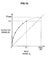
- FIG. 10 is a graph showing a relationship between the output signal (signal B) from the panel gamma generation unit 106 and the input signal (signal A) to the panel gamma generation unit 106.
- FIG. 9 is an explanatory diagram illustrating the look-up table (LUT) of the data having the characteristic opposite to the gamma characteristic of the OLED panel 120.
- the input values of the gamma curve are determined by dividing the range between 0 to A MA into 255 values.
- the LUT shown in FIG. 9A is converted by using the formula (1) below so that the input value is divided into 255 values in the range between 0 and A MA .
- Input value after conversion LUT A ⁇ 255 / A 1
- the LUT(A) is an input value included in the LUT in FIG. 9A .
- the LUT after conversion is shown in FIG. 9(B) .
- a graph corresponding to this is shown in FIG. 11.
- FIG. 11 is a graph showing a relationship between the output signal (signal B) from the panel gamma generation unit 106 and the input signal (signal A) to the panel gamma generation unit 106.
- the LUT(B) is an output value included in the LUT in FIG. 9B .
- the LUT after conversion is shown in FIG. 9(C) .
- a graph corresponding to this is shown in FIG. 12.
- FIG. 12 is a graph showing a relationship between the output signal (signal B) from the panel gamma generation unit 106 and the input signal (signal A) to the panel gamma generation unit 106.
- the panel gamma generation unit 106 can change the necessary maximum brightness without changing (decreasing) the color resolution, in other words, without the input values being changed.
- the necessary brightness calculation unit 108 calculates the brightness (the necessary maximum brightness) of the screen displayed by the organic EL display device 100 based on the user setting, the circumference environment, the video signal, and the like.
- the maximum voltage applied by the panel driver 110 to the OLED panel 120 is changed according to the necessary maximum brightness by the above method for changing the maximum brightness necessary for light emission of the OLED panel 120.
- the applicable range of the gamma curve used by the panel gamma generation unit 106 which has the characteristic opposite to the gamma characteristic of the OLED panel 120 is changed according to the necessary maximum brightness.
- the video input signal is input into the organic EL display device 100 while the maximum voltage applied to the OLED panel 120 and the gamma curve used in the panel gamma generation unit 106 are changed according to the calculated necessary maximum brightness.
- the linear gamma generation unit 105 converts the video input signal to generate the signal A, and outputs the signal A to the panel gamma generation unit 106.
- the strength of light and the signal A have a linear relationship as shown in FIG. 4 .
- the panel gamma generation unit 106 converts the signal A to generate the signal B, and outputs the signal B to the panel driver 110.
- the panel driver 110 applies the panel drive voltage to the OLED panel 120 based on the signal B.
- the signal A input into the panel gamma generation unit 106 and the brightness of the light (amount of the emitting light) emitted from the OLED panel 120 have a linear relationship as shown in FIG. 8 .
- the color resolution is not changed (decreased). For example, even when the brightness of the screen is changed, the gradation of 256 gradations which can be represented by the organic EL display device 100 can be maintained. In other words, in the embodiment, the brightness can be controlled without decreasing gradation, and further without deteriorating color.
- the organic EL display device 10 in related art includes a linear gamma generation unit 12, a brightness control gain controller 14, a panel driver 16, an OLED panel 18, and the like.
- the panel driver 16 is connected to a power supply that supplies a voltage of fixed value to the panel driver 16.
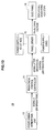
- FIG. 13 is an explanatory diagram illustrating a configuration and operation of the organic EL display device 10 in related art.
- the brightness control controller 14 when displaying an image while the brightness of the screen of the organic EL display device 10, which is a self light emitting display, is kept low, the brightness control controller 14 needs to apply a gain to the signal A output from the linear gamma generation unit 12.
- a signal of 256 gradation is input into the brightness control gain controller 14, for example, a signal of 200 gradation is output.
- the panel driver 16 outputs a panel drive voltage to the OLED panel 18.
- the gradation which can be represented by the OLED panel 18 of the organic EL display device 10 is 200.
- the brightness can be controlled, but an issue arises in gradation expression.
- various brightness of emitting light can be set according to a usage environment without changing bit depth (resolution) of the video signal. Therefore, in whatever range of the brightness of emitting light, a good image can be reproduced without generating distortion due to a bit error.
Landscapes
- Engineering & Computer Science (AREA)
- Physics & Mathematics (AREA)
- Computer Hardware Design (AREA)
- General Physics & Mathematics (AREA)
- Theoretical Computer Science (AREA)
- Control Of Indicators Other Than Cathode Ray Tubes (AREA)
- Electroluminescent Light Sources (AREA)
- Control Of El Displays (AREA)
- Transforming Electric Information Into Light Information (AREA)
Applications Claiming Priority (1)
| Application Number | Priority Date | Filing Date | Title |
|---|---|---|---|
| JP2009164051A JP2011017997A (ja) | 2009-07-10 | 2009-07-10 | 自発光表示装置及び自発光表示装置の駆動方法 |
Publications (2)
| Publication Number | Publication Date |
|---|---|
| EP2284824A2 true EP2284824A2 (de) | 2011-02-16 |
| EP2284824A3 EP2284824A3 (de) | 2011-11-30 |
Family
ID=42797596
Family Applications (1)
| Application Number | Title | Priority Date | Filing Date |
|---|---|---|---|
| EP10168048A Withdrawn EP2284824A3 (de) | 2009-07-10 | 2010-07-01 | Lichtemittierende Anzeigevorrichtung und Verfahren zum Betreiben der lichtemittierenden Anzeigevorrichtung |
Country Status (5)
| Country | Link |
|---|---|
| US (1) | US8659627B2 (de) |
| EP (1) | EP2284824A3 (de) |
| JP (1) | JP2011017997A (de) |
| KR (1) | KR20110005639A (de) |
| CN (1) | CN101950532B (de) |
Cited By (1)
| Publication number | Priority date | Publication date | Assignee | Title |
|---|---|---|---|---|
| US10748479B2 (en) | 2016-12-07 | 2020-08-18 | Semiconductor Energy Laboratories Co., Ltd. | Semiconductor device, display system, and electronic device |
Families Citing this family (9)
| Publication number | Priority date | Publication date | Assignee | Title |
|---|---|---|---|---|
| KR101679360B1 (ko) * | 2010-08-05 | 2016-11-25 | 삼성디스플레이 주식회사 | 계조전압 생성장치 및 방법, 및 유기전계발광표시장치 |
| US20140273681A1 (en) * | 2013-03-15 | 2014-09-18 | Rolls-Royce Corporation | Sic based ceramic matrix composites with layered matrices and methods for producing sic based ceramic matrix composites with layered matrices |
| KR102288250B1 (ko) * | 2014-03-31 | 2021-08-11 | 소니그룹주식회사 | 화상 처리 장치, 화상 처리 방법 및 프로그램 |
| JP2016090922A (ja) * | 2014-11-10 | 2016-05-23 | 株式会社ジャパンディスプレイ | El表示装置及びその制御方法 |
| CN105070252B (zh) * | 2015-08-13 | 2018-05-08 | 小米科技有限责任公司 | 降低显示亮度的方法及装置 |
| KR102433924B1 (ko) | 2016-01-14 | 2022-08-19 | 삼성전자주식회사 | 디스플레이 컨트롤러, 그리고 이를 포함하는 어플리케이션 프로세서 |
| CN106157897B (zh) | 2016-09-26 | 2018-11-20 | 京东方科技集团股份有限公司 | 一种亮度控制方法、装置、amoled面板和电子设备 |
| US10753773B2 (en) * | 2017-12-21 | 2020-08-25 | Dell Products L.P. | Display device relative angle detection system |
| WO2022010509A1 (en) * | 2020-07-06 | 2022-01-13 | Google Llc | Under-display sensor operation |
Citations (2)
| Publication number | Priority date | Publication date | Assignee | Title |
|---|---|---|---|---|
| JP2005208241A (ja) | 2004-01-21 | 2005-08-04 | Nec Electronics Corp | 発光素子駆動回路 |
| JP2008151946A (ja) | 2006-12-15 | 2008-07-03 | Sanyo Electric Co Ltd | エレクトロルミネッセンス表示装置 |
Family Cites Families (10)
| Publication number | Priority date | Publication date | Assignee | Title |
|---|---|---|---|---|
| JP2005260849A (ja) * | 2004-03-15 | 2005-09-22 | Toshiba Corp | 表示装置と表示方法 |
| JP2006163290A (ja) * | 2004-12-10 | 2006-06-22 | Canon Inc | 画像表示装置 |
| KR100624136B1 (ko) * | 2005-08-22 | 2006-09-13 | 삼성에스디아이 주식회사 | 자동밝기 조절장치를 포함하는 유기 전계발광 표시장치 |
| JP2007199375A (ja) * | 2006-01-26 | 2007-08-09 | Denso Corp | 電圧駆動型表示装置 |
| KR101279117B1 (ko) * | 2006-06-30 | 2013-06-26 | 엘지디스플레이 주식회사 | 유기발광다이오드 표시소자 및 그의 구동 방법 |
| KR100844775B1 (ko) | 2007-02-23 | 2008-07-07 | 삼성에스디아이 주식회사 | 유기 전계발광 표시장치 |
| JP2008209886A (ja) | 2007-02-23 | 2008-09-11 | Samsung Sdi Co Ltd | 有機電界発光表示装置及びその駆動方法 |
| JP4450012B2 (ja) * | 2007-05-11 | 2010-04-14 | ソニー株式会社 | 有機elパネルの表示補正回路 |
| KR101443371B1 (ko) * | 2007-07-13 | 2014-09-29 | 엘지디스플레이 주식회사 | 액정표시장치 및 그의 구동방법 |
| CN101261821B (zh) * | 2008-05-08 | 2012-07-04 | 友达光电股份有限公司 | 伽玛曲线补偿方法、伽玛曲线补偿电路以及显示系统 |
-
2009
- 2009-07-10 JP JP2009164051A patent/JP2011017997A/ja active Pending
-
2010
- 2010-06-08 US US12/796,090 patent/US8659627B2/en active Active
- 2010-07-01 EP EP10168048A patent/EP2284824A3/de not_active Withdrawn
- 2010-07-02 KR KR1020100063759A patent/KR20110005639A/ko not_active Ceased
- 2010-07-05 CN CN2010102222677A patent/CN101950532B/zh active Active
Patent Citations (2)
| Publication number | Priority date | Publication date | Assignee | Title |
|---|---|---|---|---|
| JP2005208241A (ja) | 2004-01-21 | 2005-08-04 | Nec Electronics Corp | 発光素子駆動回路 |
| JP2008151946A (ja) | 2006-12-15 | 2008-07-03 | Sanyo Electric Co Ltd | エレクトロルミネッセンス表示装置 |
Cited By (1)
| Publication number | Priority date | Publication date | Assignee | Title |
|---|---|---|---|---|
| US10748479B2 (en) | 2016-12-07 | 2020-08-18 | Semiconductor Energy Laboratories Co., Ltd. | Semiconductor device, display system, and electronic device |
Also Published As
| Publication number | Publication date |
|---|---|
| CN101950532A (zh) | 2011-01-19 |
| JP2011017997A (ja) | 2011-01-27 |
| US8659627B2 (en) | 2014-02-25 |
| CN101950532B (zh) | 2013-06-05 |
| KR20110005639A (ko) | 2011-01-18 |
| EP2284824A3 (de) | 2011-11-30 |
| US20110007101A1 (en) | 2011-01-13 |
Similar Documents
| Publication | Publication Date | Title |
|---|---|---|
| US8659627B2 (en) | Self light emitting display device for adjusting a necessary brightness based on user setting, outside light or video signal | |
| US11282480B2 (en) | Device and method for display brightness control | |
| US10504217B2 (en) | Method and module for processing high dynamic range (HDR) image and display device using the same | |
| US9269301B2 (en) | Self-lighting display device and method of driving the same | |
| KR101399304B1 (ko) | 액정표시장치 및 그 구동방법 | |
| US8711084B2 (en) | Device and method for controlling brightness of organic light emitting diode display | |
| US8054286B2 (en) | Liquid crystal display capable of adjusting brightness of backlight thereof and method for driving same | |
| KR102177725B1 (ko) | 피크휘도제어부를 포함하는 유기발광다이오드 표시장치 및 그 구동방법 | |
| KR101157109B1 (ko) | 디스플레이 디바이스 내의 전력 레벨 제어 및/또는 콘트라스트 제어를 위한 방법 및 장치 | |
| JP4627773B2 (ja) | 駆動回路装置 | |
| KR102046443B1 (ko) | 표시 장치 및 그의 영상 보상 방법 | |
| JP2006506664A (ja) | 液晶表示装置及びその駆動方法 | |
| KR20140058283A (ko) | 표시 장치 및 표시 장치의 구동 방법 | |
| JP2004252409A (ja) | 画像表示装置 | |
| KR20150078029A (ko) | 감마전압 발생부와 이를 포함하는 표시장치 | |
| US20190026872A1 (en) | Driving circuit of processing high dynamic range image signal and display device having the same | |
| KR102438252B1 (ko) | 하이 다이나믹 레인지를 위한 4색 표시 장치 | |
| KR20150075804A (ko) | 감마전압 발생부와 이를 포함하는 표시장치 | |
| JP2012058719A (ja) | 有機発光ダイオード駆動装置 | |
| KR102005391B1 (ko) | 피크휘도제어부를 포함하는 유기발광다이오드 표시장치 및 그 구동방법 | |
| KR20100072448A (ko) | 광원 구동 방법, 이를 수행하기 위한 광원 장치 및 이 광원장치를 갖는 표시 장치 | |
| CN100442331C (zh) | 平面显示器及其图像校正电路与方法 | |
| KR102954161B1 (ko) | 반도체 장치 | |
| KR101764606B1 (ko) | 유기 발광 표시장치와 이의 구동방법 | |
| JP2006106147A (ja) | 表示装置及び表示方法 |
Legal Events
| Date | Code | Title | Description |
|---|---|---|---|
| PUAI | Public reference made under article 153(3) epc to a published international application that has entered the european phase |
Free format text: ORIGINAL CODE: 0009012 |
|
| 17P | Request for examination filed |
Effective date: 20100701 |
|
| AK | Designated contracting states |
Kind code of ref document: A2 Designated state(s): AL AT BE BG CH CY CZ DE DK EE ES FI FR GB GR HR HU IE IS IT LI LT LU LV MC MK MT NL NO PL PT RO SE SI SK SM TR |
|
| AX | Request for extension of the european patent |
Extension state: BA ME RS |
|
| PUAL | Search report despatched |
Free format text: ORIGINAL CODE: 0009013 |
|
| AK | Designated contracting states |
Kind code of ref document: A3 Designated state(s): AL AT BE BG CH CY CZ DE DK EE ES FI FR GB GR HR HU IE IS IT LI LT LU LV MC MK MT NL NO PL PT RO SE SI SK SM TR |
|
| AX | Request for extension of the european patent |
Extension state: BA ME RS |
|
| RIC1 | Information provided on ipc code assigned before grant |
Ipc: G09G 3/32 20060101AFI20111025BHEP |
|
| 17Q | First examination report despatched |
Effective date: 20111111 |
|
| STAA | Information on the status of an ep patent application or granted ep patent |
Free format text: STATUS: THE APPLICATION IS DEEMED TO BE WITHDRAWN |
|
| 18D | Application deemed to be withdrawn |
Effective date: 20140201 |