EP2284851A2 - Dispositif de transfert pour commutateur de transfert automatique - Google Patents
Dispositif de transfert pour commutateur de transfert automatique Download PDFInfo
- Publication number
- EP2284851A2 EP2284851A2 EP10172620A EP10172620A EP2284851A2 EP 2284851 A2 EP2284851 A2 EP 2284851A2 EP 10172620 A EP10172620 A EP 10172620A EP 10172620 A EP10172620 A EP 10172620A EP 2284851 A2 EP2284851 A2 EP 2284851A2
- Authority
- EP
- European Patent Office
- Prior art keywords
- link
- trip
- closing
- coupled
- transmission
- Prior art date
- Legal status (The legal status is an assumption and is not a legal conclusion. Google has not performed a legal analysis and makes no representation as to the accuracy of the status listed.)
- Granted
Links
Images




Classifications
-
- H—ELECTRICITY
- H01—ELECTRIC ELEMENTS
- H01H—ELECTRIC SWITCHES; RELAYS; SELECTORS; EMERGENCY PROTECTIVE DEVICES
- H01H9/00—Details of switching devices, not covered by groups H01H1/00 - H01H7/00
- H01H9/20—Interlocking, locking, or latching mechanisms
- H01H9/26—Interlocking, locking, or latching mechanisms for interlocking two or more switches
-
- H—ELECTRICITY
- H01—ELECTRIC ELEMENTS
- H01H—ELECTRIC SWITCHES; RELAYS; SELECTORS; EMERGENCY PROTECTIVE DEVICES
- H01H31/00—Air-break switches for high tension without arc-extinguishing or arc-preventing means
- H01H31/02—Details
- H01H31/04—Interlocking mechanisms
-
- H—ELECTRICITY
- H01—ELECTRIC ELEMENTS
- H01H—ELECTRIC SWITCHES; RELAYS; SELECTORS; EMERGENCY PROTECTIVE DEVICES
- H01H71/00—Details of the protective switches or relays covered by groups H01H73/00 - H01H83/00
- H01H71/10—Operating or release mechanisms
- H01H71/12—Automatic release mechanisms with or without manual release
- H01H71/123—Automatic release mechanisms with or without manual release using a solid-state trip unit
-
- H—ELECTRICITY
- H01—ELECTRIC ELEMENTS
- H01H—ELECTRIC SWITCHES; RELAYS; SELECTORS; EMERGENCY PROTECTIVE DEVICES
- H01H73/00—Protective overload circuit-breaking switches in which excess current opens the contacts by automatic release of mechanical energy stored by previous operation of a hand reset mechanism
-
- H—ELECTRICITY
- H01—ELECTRIC ELEMENTS
- H01H—ELECTRIC SWITCHES; RELAYS; SELECTORS; EMERGENCY PROTECTIVE DEVICES
- H01H83/00—Protective switches, e.g. circuit-breaking switches, or protective relays operated by abnormal electrical conditions otherwise than solely by excess current
-
- H—ELECTRICITY
- H02—GENERATION; CONVERSION OR DISTRIBUTION OF ELECTRIC POWER
- H02B—BOARDS, SUBSTATIONS OR SWITCHING ARRANGEMENTS FOR THE SUPPLY OR DISTRIBUTION OF ELECTRIC POWER
- H02B11/00—Switchgear having carriage withdrawable for isolation
- H02B11/12—Switchgear having carriage withdrawable for isolation with isolation by horizontal withdrawal
- H02B11/127—Withdrawal mechanism
- H02B11/133—Withdrawal mechanism with interlock
-
- H—ELECTRICITY
- H01—ELECTRIC ELEMENTS
- H01H—ELECTRIC SWITCHES; RELAYS; SELECTORS; EMERGENCY PROTECTIVE DEVICES
- H01H3/00—Mechanisms for operating contacts
- H01H3/32—Driving mechanisms, i.e. for transmitting driving force to the contacts
- H01H2003/323—Driving mechanisms, i.e. for transmitting driving force to the contacts the mechanisms being adjustable
-
- H—ELECTRICITY
- H01—ELECTRIC ELEMENTS
- H01H—ELECTRIC SWITCHES; RELAYS; SELECTORS; EMERGENCY PROTECTIVE DEVICES
- H01H2300/00—Orthogonal indexing scheme relating to electric switches, relays, selectors or emergency protective devices covered by H01H
- H01H2300/018—Application transfer; between utility and emergency power supply
Definitions
- the present invention relates to a transfer device for an automatic transfer switch, and particularly, to a transfer device for an automatic transfer switch, by which various electric components are allowed to be continuously supplied with stable power in a manner of blocking one air circuit breaker from being mechanically electrically closed when another air circuit breaker is closed due to a switching of states between the two air circuit breakers.
- ATS automatic transfer switch
- the ATS includes therein a regular air circuit breaker (hereinafter, referred to as a first ACB) and an emergency air circuit breaker (hereinafter, referred to as a second ACB).
- the first and second ACBs are mechanically connected to each other to be switched to each other. Accordingly, when a fault current is applied to one of the two ACBs, such fault current is detected. Consequently, a closed ACB is tripped and simultaneously another ACB is closed so as to be switched to each other.
- the switching of the ACBs allows a constant supply of stable power.
- the two ACBs Upon allowing the switching of the two ACBs for use, the two ACBs are typically connected to each other via a wire or a thin iron bar for allowing an interlocking of the ACBs.
- FIGS. 1 and 2 are perspective views showing an example of a related art device for interlocking two ACBs using a thin iron bar.
- the related art ATS includes frames 11 and 21 installed at the ACBs 1 and 2, respectively, closing links 12 and 22 rotatably coupled to the frames 11 and 21, respectively, to be rotatable by respective closing levers (not shown) installed within each ACB 1 and 2, trip links 13 and 23 rotatably installed in the frames 11 and 21, respectively, at one sides of the corresponding closing links 12 and 22 so as to cooperate with respective trip levers (not shown) installed in each ACB 1 and 2, and transmission rods 14 and 24 connected between the closing links 12 and 22 and the trip links 13 and 23 so as to transfer a rotational force.
- the closing links 12 and 22 and the trip links 13 and 23 are installed independent of each other, and each of the transmission rods 14 and 24 is made of an integrally rigid material.
- each transmission rod 14, 24 should be adjusted by cutting off the transmission rod 14, 24, which makes it difficult to fabricate the transmission rods 14 and 24 with exactly the same length between the closing links 12 and 22 and the trip links 13 and 23, and also makes it difficult to adjust an error occurred during the assembly operation, which may cause a mis-operation to occur due to a defective assembly.
- each of the ACBs 1 and 2 is repeatedly closed and tripped, upon rotation of the closing links 12 and 22 and the trip links 13 and 23, an impact transferred to each transmission rod 14, 24 cannot be absorbed, thereby generating impact noise or degrading durability.
- each transmission rod 14, 24 is formed of a thin rod, so it has a low intensity. Also, since each of the transmission rods 14, 24 has a structurally bent portion, it may have high possibility of being curved during operation, which may cause a mis-operation.
- an object of the present disclosure is to provide a transfer device for an automatic transfer switch capable of reducing the number of assembly processes by modularizing a closing link and a trip link of each ACB.
- Another object of the present disclosure is to provide a transfer device for an automatic transfer switch capable of avoiding beforehand a mis-operation by facilitating adjustment of a length of a transmission rod between the closing link and the trip link.
- Another object of the present disclosure is to provide a transfer device for an automatic transfer switch capable of reducing noise and increasing durability by allowing an impact generated upon repetition of closing and tripling of each ACB to be absorbed at the transmission rod.
- Another object of the present disclosure is to provide a transfer device for an automatic transfer switch, capable of avoiding in advance (minimizing) a mis-operation caused due to a transmission rod being curved or the like upon a switching operation, in a manner of increasing an intensity of the transmission rod.
- a transfer device for an automatic transfer switch including closing links and trip links disposed to be rotatable in cooperation with a closing operation and a trip operation of a plurality of air circuit breakers, respectively, and transmission rods each having both ends coupled to the corresponding closing link and trip link to allow cooperation of the closing operation and the trip operation of the plurality of air circuit breakers, wherein each of the transmission rods comprises a length-adjusting unit configured to allow adjustment of the length of the transmission rod in a state that both ends thereof are coupled the corresponding closing link and trip link.
- Each of the transmission rods may be configured by a plurality of links provided in pair, one ends of the links provided in pair may be coupled to the closing links and the trip links, respectively, and another ends thereof may be screw-coupled to each other so as to adjust lengths of the transmission rods.
- Each of the transmission rods may be provided with a closing side transmission link and a trip side transmission link, and a nut-type length-adjusting unit may be provided between the closing side transmission link and the trip side transmission link so as to couple the same in a manner of coupling with a nut.
- Each of the transmission rods may include a buffer configured to absorb an impact generated when a position of the transmission rod is changed in response to operations of the closing link and the trip link.
- Each of the plurality of air circuit breakers may include a frame base, and a frame cover may be coupled to one side surface of each frame base with a preset interval, the closing link and the trip link being rotatably coupled between the frame base and the frame cover.
- the closing link may be rotatably coupled to one side surface of each frame base, a link configuring the transmission rod may be rotatably coupled to one side of the closing link, and a closing lever for selectively rotating the closing link may be slidably coupled to another side of the closing link.
- the trip link may be rotatably coupled to one side surface of each frame base, a trip lever for operating an interlock lever for maintaining and releasing a tripped state of each air circuit breaker may be rotatably coupled to another side surface of the frame base, and the trip link and the trip lever may be coupled to each other with interposing the frame base therebetween so as to cooperate with each other.
- FIG. 3 is a front view showing an automatic transfer switch in accordance with an exemplary embodiment
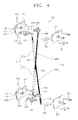
- FIG. 4 is a perspective view of a transfer device disassembled from the automatic transfer switch of FIG. 3 .
- an automatic transfer switch (ATS) 100 may include a case 101 having an accommodation space partitioned into upper and lower spaces, a regular ACB (first ACB) 110 disposed in the upper accommodation space of the case 101, and an emergency ACB (second ACB) 120 disposed in the lower accommodation space of the case 101.
- a transfer device 200 for alternately closing or tripping both the ACBs 110 and 120 may be installed in one side of the inner space of the case 101, namely, in one sides of the first and second ACBs 110 and 120.
- the transfer device 200 may be modularized to be easily installed between the first ACB 110 and the second ACB 120.
- the transfer device 200 may include a first frame base 211 and a second frame base 221 disposed at one side surfaces of the first ACB 110 and the second ACB 120, respectively, a first frame cover 212 and a second frame cover 222 coupled to one side surfaces of the first and second frame bases 211 and 221, respectively, with preset intervals, a first closing link 213 and a first trip link 214 coupled to be present between the frame bases 211 and 221 and the frame covers 212 and 222, respectively, so as to selectively perform a closing operation and a trip operation, a second closing link 223 and a second trip link 224 coupled to be present between the frame bases 211 and 221 and the frame covers 212 and 222, respectively, so as to selectively perform the closing operation and the trip operation with moving opposite to the first closing link 213 and the first trip link 214, and a first transmission rod 215 and
- Each of the first frame base 211 and the second frame base 221 may be formed in a shape of an approximately rectangular panel. Near edges of the first and second frame bases 211 and 221 are shown, respectively having coupling holes 211 a and 221 a for fixing the first and second frame bases 211 and 221 to one side surfaces of the ACBs 110 and 120, respectively, through holes 211b and 221 b for coupling of the closing links 213 and 223, respectively, coupling holes 211 c and 221 c for fixing the frame covers 212 and 222, respectively, and the like. At central portions of the frame bases 211 and 221 are shown, having through holes 211 d and 221 d for coupling of the trip links 224 and 214, respectively.
- the first frame cover 212 and the second frame cover 222 may be coupled to outer side surfaces of the frame bases 211 and 221, respectively, with preset intervals.
- a plurality of pins 216 and 226 for maintaining the intervals may be disposed along edges of each frame base 211 and 221 and each frame cover 212 and 222, so as to be fixed by bolts 217 and 227, respectively.
- Some of the plurality of pins 216 and 226 may be engaged with one side surfaces of the ACBs 110 and 120, respectively, via the frame bases 211 and 221.
- the first closing link 213 may be rotatably installed at the through hole 211 b disposed at the edge of the first frame base 211.
- a first closing side transmission link 215a of the first transmission rod 215 to be explained later may be rotatably coupled to one end of the first closing link 213.
- a coupling groove 213a for allowing a closing lever 111 (see FIG. 6 ) of the first ACB 110 to be slidably rotated may be formed at another end of the first closing link 213 long in a lengthwise direction.
- the first trip link 214 may be rotatably installed at the through hole 221 d present at the central portion of the second frame base 221.
- a first trip side transmission link 215b of the first transmission rod 215 to be explained later may be rotatably coupled to one end of the first trip link 214.
- a pin 214a inserted through the sliding hole 221e of the second frame base 221 may be coupled to another end of the first trip link 214.
- the pin 214a may be slidably coupled to the trip lever 122 of the second ACB 120.
- the trip lever 122 of the second ACB 120 may be coupled to an interlock lever 123 (see FIG. 6 ) of the second ACB 120 so as to operate the interlock lever 123 for maintaining or releasing a tripped state of the second ACB 120.
- the first transmission rod 215 may be provided with a plurality of links having one ends coupled to the first closing link 213 and the first trip link 214, respectively.
- the first transmission rod 215 may include a first closing side transmission link 215a and a first trip side transmission link 215b.
- the first closing side transmission link 215a as aforesaid, may have one end, which is rotatably coupled to the first closing link 213 so as to be movable up and down responsive to a direction that the first closing link 213 rotates.
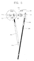
- a nut-type length-adjusting unit 215c may be formed at another end of the first closing side transmission link 215a, namely, at another end which is not coupled to the first closing link 213, such that an end of the first trip side transmission link 215b is inserted thereinto to be coupled by a screw.
- the first trip side transmission link 215b may have one end rotatably coupled to the first trip link 214.
- a screw thread which is to be inserted into the length-adjusting unit 215c of the first closing side transmission link 215a to be screw-coupled, may be formed at another end of the first trip side transmission link 215b, namely, at another end which is not coupled to the first trip link 214.
- first and second transmission rods 215 and 225 coupled with the first and second trip links 214 and 224, respectively are shown, having buffers 215d and 225d configured as compression coil springs for attenuating impacts applied to the transmission rods 215 and 225, respectively, when the first and second transmission rods 215 and 225 are closed or tripped.
- the second closing link 223 may be substantially the same as the aforesaid first closing link 213 in its shape and assembled position except for being coupled to the second frame base 221 and coupled to a second closing side transmission link 225a of the second transmission rod 225.
- the second trip link 224 may be substantially the same as the aforesaid first trip link 214 in its shape and assembled position except for being coupled to the first frame base 211 and coupled to a second trip side transmission link 225b of the second transmission rod 225.
- the second transmission rod 225 may be substantially the same as the first transmission rod 215 in its configuration and operation principle excluding members assembled thereto and its position.
- a closing link driving lever 111 connected to the first ACB 110 rotates in a counterclockwise direction in the drawing.
- the first closing link 213 accordingly rotates in a counterclockwise direction in the drawing, and the first transmission rod 215 connected between the first closing link 213 of the first ACB 110 and the first trip link 214 of the second ACB 120 moves upwardly.
- the first trip link 214 rotates in the counterclockwise direction in the drawing.
- the trip lever 122 of the second ACB 120 is pushed up due to the rotation of the first trip link 214.
- the interlock lever 123 of the second ACB 120 operates such that the second ACB 120 is tripped.
- the first closing link 213 moves back to its original position and the first trip link 214 of the second ACB 120 is also restored to its original position by virtue of the first transmission rod 215.
- the trip lever 122 of the second ACB 120 is moved back to its original position. Accordingly, the second ACB 120 is released from the interlocked state, thereby being able to be closed.
- the second closing link 224 moves back to its original position and the second trip link 224 of the first ACB 110 is also restored to its original position by virtue of the second transmission rod 225.
- the trip lever 112 of the first ACB 110 moves back to its original position. Accordingly, the first ACB 120 is uninterlocked, thereby being able to be closed.
- a transfer device which is installed between plural ACBs to make the plural ACBs alternately switched to a closed state and a tripped state may be modularized, thereby facilitating an assembly of the transfer device.
- a length of a transmission rod configuring part of the transfer device can be adjusted, which allows the transfer device to be easily assembled and repaired or maintained and also reduces the probability of occurrence of an assembly error so as to enable more accurate closing and trip operations.
- an impact which may occur upon switching the closing and trip operations of each ACB, can be absorbed, thereby reducing impact noise and enhancing reliability.
- the transmission rod is formed with a preset thickness without being curved, so curving or bending of the transmission rod can be avoided in advance, whereby a mis-operation during the closing and trip operations may not occur.
Landscapes
- Physics & Mathematics (AREA)
- Electromagnetism (AREA)
- Engineering & Computer Science (AREA)
- Power Engineering (AREA)
- Driving Mechanisms And Operating Circuits Of Arc-Extinguishing High-Tension Switches (AREA)
- Push-Button Switches (AREA)
Applications Claiming Priority (1)
| Application Number | Priority Date | Filing Date | Title |
|---|---|---|---|
| KR1020090075299A KR101082216B1 (ko) | 2009-08-14 | 2009-08-14 | 자동제어 절환기기의 절환 장치 |
Publications (3)
| Publication Number | Publication Date |
|---|---|
| EP2284851A2 true EP2284851A2 (fr) | 2011-02-16 |
| EP2284851A3 EP2284851A3 (fr) | 2012-05-09 |
| EP2284851B1 EP2284851B1 (fr) | 2016-10-05 |
Family
ID=43063879
Family Applications (1)
| Application Number | Title | Priority Date | Filing Date |
|---|---|---|---|
| EP10172620.6A Active EP2284851B1 (fr) | 2009-08-14 | 2010-08-12 | Dispositif de transfert pour commutateur de transfert automatique |
Country Status (6)
| Country | Link |
|---|---|
| US (1) | US8431846B2 (fr) |
| EP (1) | EP2284851B1 (fr) |
| JP (1) | JP5209680B2 (fr) |
| KR (1) | KR101082216B1 (fr) |
| CN (1) | CN101996788B (fr) |
| ES (1) | ES2609420T3 (fr) |
Cited By (4)
| Publication number | Priority date | Publication date | Assignee | Title |
|---|---|---|---|---|
| EP2892068A4 (fr) * | 2012-08-30 | 2016-05-04 | Seari Electric Technology Co Ltd | Appareil de commutateur de transfert automatique |
| EP2892069A4 (fr) * | 2012-08-30 | 2016-06-22 | Seari Electric Technology Co Ltd | Appareil de verrouillage de commutateur de transfert automatique |
| CN105788940A (zh) * | 2016-04-29 | 2016-07-20 | 句容华源电器设备有限公司 | 一种推拉式隔离开关 |
| EP3839997A1 (fr) * | 2019-12-18 | 2021-06-23 | Schneider Electric Industries SAS | Système de protection électrique multipolaire et installation électrique comprenant un tel système |
Families Citing this family (10)
| Publication number | Priority date | Publication date | Assignee | Title |
|---|---|---|---|---|
| US9467006B2 (en) | 2013-09-23 | 2016-10-11 | Trippe Manufacturing Company | Automatic transfer switch for three-phase applications |
| CN105761963A (zh) * | 2016-04-29 | 2016-07-13 | 句容华源电器设备有限公司 | 一种安全隔离开关 |
| CN106298309B (zh) * | 2016-10-13 | 2018-04-17 | 沈阳斯沃电器有限公司 | 双旁路自动转换开关 |
| KR101910388B1 (ko) | 2017-04-11 | 2018-10-22 | 엘에스산전 주식회사 | 차단기의 인터로크 장치 |
| KR101909017B1 (ko) | 2017-05-23 | 2018-10-18 | 현대일렉트릭앤에너지시스템(주) | 차단기의 인터록 장치 |
| US11239692B2 (en) | 2018-07-25 | 2022-02-01 | Wen-Feng Lu | Automatic transfer switch utilizing back-to-back mounted molded case circuit breakers or molded case switches to connect a load to a normal power source and a standby power source |
| CN112017880B (zh) * | 2019-05-30 | 2024-10-22 | 上海良信电器股份有限公司 | 一种中性线重叠时间可调的自动转换开关 |
| CN111725011B (zh) * | 2020-06-19 | 2022-05-27 | 浙江曙天电器有限公司 | 双电源自动转换开关 |
| CN112038189B (zh) * | 2020-08-19 | 2022-02-18 | 苏州飞腾电器有限公司 | 一种三电源自动转换开关 |
| WO2022222033A1 (fr) * | 2021-04-20 | 2022-10-27 | Abb Schweiz Ag | Système de verrouillage mécanique et appareillage de commutation le comprenant |
Family Cites Families (10)
| Publication number | Priority date | Publication date | Assignee | Title |
|---|---|---|---|---|
| JPS55127322U (fr) | 1978-10-04 | 1980-09-09 | ||
| US4286242A (en) * | 1979-09-17 | 1981-08-25 | Westinghouse Electric Corp. | Mechanical interlock for low voltage circuit breakers |
| JPS6235227Y2 (fr) | 1980-06-24 | 1987-09-08 | ||
| US4760278A (en) * | 1987-07-23 | 1988-07-26 | Thomson Robert G | Transfer switch |
| US5288958A (en) * | 1992-03-30 | 1994-02-22 | Westinghouse Electric Corp. | Lockable remote rotary handle operator for circuit breakers |
| JP3489859B2 (ja) | 1993-12-03 | 2004-01-26 | 株式会社勝亦電機製作所 | 電源切替器 |
| US5929405A (en) * | 1998-05-07 | 1999-07-27 | Eaton Corporation | Interlock for electrical switching apparatus with stored energy closing |
| CN1143342C (zh) | 1998-06-05 | 2004-03-24 | Lg产电株式会社 | 断路器跳闸连接机构 |
| KR200183457Y1 (ko) * | 1999-12-22 | 2000-05-15 | 엘지산전주식회사 | 기중차단기의 기계적 인터록 장치 |
| US6486421B1 (en) | 2000-04-27 | 2002-11-26 | Eaton Corporation | Mechanical interlock with overtravel compensation for coordinating operation of circuit breakers |
-
2009
- 2009-08-14 KR KR1020090075299A patent/KR101082216B1/ko active Active
-
2010
- 2010-08-12 ES ES10172620.6T patent/ES2609420T3/es active Active
- 2010-08-12 EP EP10172620.6A patent/EP2284851B1/fr active Active
- 2010-08-12 US US12/855,105 patent/US8431846B2/en active Active
- 2010-08-13 JP JP2010181431A patent/JP5209680B2/ja active Active
- 2010-08-16 CN CN201010503690.4A patent/CN101996788B/zh active Active
Non-Patent Citations (1)
| Title |
|---|
| None |
Cited By (7)
| Publication number | Priority date | Publication date | Assignee | Title |
|---|---|---|---|---|
| EP2892068A4 (fr) * | 2012-08-30 | 2016-05-04 | Seari Electric Technology Co Ltd | Appareil de commutateur de transfert automatique |
| EP2892069A4 (fr) * | 2012-08-30 | 2016-06-22 | Seari Electric Technology Co Ltd | Appareil de verrouillage de commutateur de transfert automatique |
| CN105788940A (zh) * | 2016-04-29 | 2016-07-20 | 句容华源电器设备有限公司 | 一种推拉式隔离开关 |
| CN105788940B (zh) * | 2016-04-29 | 2017-11-03 | 利辛县江淮扬天汽车有限公司 | 一种推拉式隔离开关 |
| EP3839997A1 (fr) * | 2019-12-18 | 2021-06-23 | Schneider Electric Industries SAS | Système de protection électrique multipolaire et installation électrique comprenant un tel système |
| FR3105566A1 (fr) * | 2019-12-18 | 2021-06-25 | Schneider Electric Industries Sas | Système de protection électrique multipolaire et installation électrique comprenant un tel système |
| US11764551B2 (en) | 2019-12-18 | 2023-09-19 | Schneider Electric Industries Sas | Multipolar electrical protection system and electrical installation comprising such a system |
Also Published As
| Publication number | Publication date |
|---|---|
| CN101996788B (zh) | 2014-03-19 |
| JP2011040394A (ja) | 2011-02-24 |
| EP2284851A3 (fr) | 2012-05-09 |
| EP2284851B1 (fr) | 2016-10-05 |
| CN101996788A (zh) | 2011-03-30 |
| US8431846B2 (en) | 2013-04-30 |
| KR101082216B1 (ko) | 2011-11-09 |
| KR20110017697A (ko) | 2011-02-22 |
| US20110036695A1 (en) | 2011-02-17 |
| ES2609420T3 (es) | 2017-04-20 |
| JP5209680B2 (ja) | 2013-06-12 |
Similar Documents
| Publication | Publication Date | Title |
|---|---|---|
| EP2284851B1 (fr) | Dispositif de transfert pour commutateur de transfert automatique | |
| US10410810B2 (en) | Switching device for LV electric installations | |
| CN101404232B (zh) | 用于断路器的接触臂机构 | |
| CN101369502A (zh) | 电气开关设备、锁闩组件及其锁闩接合度控制机构 | |
| US9384912B2 (en) | Circuit breaker | |
| CN102651292B (zh) | 断路器 | |
| CN101354991B (zh) | 电气开关设备及其跳闸致动器组件 | |
| US7646270B2 (en) | Electrical switching apparatus, and yoke assembly and spring assembly therefor | |
| CN101354990B (zh) | 电气开关设备及其跳闸致动器组件和复位组件 | |
| EP3392898B1 (fr) | Dispositif de déclenchement magnétique d'un disjoncteur à air | |
| CN101350273B (zh) | 电气开关设备及其跳闸致动器复位组件 | |
| EP2204826B1 (fr) | Unité de pressage élastique et disjoncteur en boîtier moulé doté de celle-ci | |
| US10811209B2 (en) | Switching mechanism of circuit breaker | |
| JP6270541B2 (ja) | 開閉器操作機構 | |
| US7586394B2 (en) | Electrical switching apparatus, and trip actuator reset assembly and lever arm assembly therefor | |
| CN114667585B (zh) | 横杆组装体及包括该横杆组装体的跳闸装置 | |
| JP6858932B1 (ja) | 回路遮断器 | |
| CN105374644A (zh) | 脱扣杆止挡装置 | |
| CN111566772B (zh) | 断路器 | |
| CN116830232A (zh) | 漏电断路器 |
Legal Events
| Date | Code | Title | Description |
|---|---|---|---|
| PUAI | Public reference made under article 153(3) epc to a published international application that has entered the european phase |
Free format text: ORIGINAL CODE: 0009012 |
|
| AK | Designated contracting states |
Kind code of ref document: A2 Designated state(s): AL AT BE BG CH CY CZ DE DK EE ES FI FR GB GR HR HU IE IS IT LI LT LU LV MC MK MT NL NO PL PT RO SE SI SK SM TR |
|
| AX | Request for extension of the european patent |
Extension state: BA ME RS |
|
| PUAL | Search report despatched |
Free format text: ORIGINAL CODE: 0009013 |
|
| AK | Designated contracting states |
Kind code of ref document: A3 Designated state(s): AL AT BE BG CH CY CZ DE DK EE ES FI FR GB GR HR HU IE IS IT LI LT LU LV MC MK MT NL NO PL PT RO SE SI SK SM TR |
|
| AX | Request for extension of the european patent |
Extension state: BA ME RS |
|
| RIC1 | Information provided on ipc code assigned before grant |
Ipc: H01H 9/26 20060101AFI20120403BHEP Ipc: H01H 3/32 20060101ALN20120403BHEP |
|
| 17P | Request for examination filed |
Effective date: 20121106 |
|
| GRAP | Despatch of communication of intention to grant a patent |
Free format text: ORIGINAL CODE: EPIDOSNIGR1 |
|
| RIC1 | Information provided on ipc code assigned before grant |
Ipc: H01H 3/32 20060101ALN20160307BHEP Ipc: H01H 9/26 20060101AFI20160307BHEP |
|
| INTG | Intention to grant announced |
Effective date: 20160407 |
|
| GRAS | Grant fee paid |
Free format text: ORIGINAL CODE: EPIDOSNIGR3 |
|
| GRAA | (expected) grant |
Free format text: ORIGINAL CODE: 0009210 |
|
| AK | Designated contracting states |
Kind code of ref document: B1 Designated state(s): AL AT BE BG CH CY CZ DE DK EE ES FI FR GB GR HR HU IE IS IT LI LT LU LV MC MK MT NL NO PL PT RO SE SI SK SM TR |
|
| REG | Reference to a national code |
Ref country code: GB Ref legal event code: FG4D |
|
| REG | Reference to a national code |
Ref country code: CH Ref legal event code: EP |
|
| REG | Reference to a national code |
Ref country code: AT Ref legal event code: REF Ref document number: 835259 Country of ref document: AT Kind code of ref document: T Effective date: 20161015 |
|
| REG | Reference to a national code |
Ref country code: IE Ref legal event code: FG4D |
|
| REG | Reference to a national code |
Ref country code: DE Ref legal event code: R096 Ref document number: 602010036894 Country of ref document: DE |
|
| REG | Reference to a national code |
Ref country code: NL Ref legal event code: MP Effective date: 20161005 |
|
| REG | Reference to a national code |
Ref country code: LT Ref legal event code: MG4D |
|
| PG25 | Lapsed in a contracting state [announced via postgrant information from national office to epo] |
Ref country code: LV Free format text: LAPSE BECAUSE OF FAILURE TO SUBMIT A TRANSLATION OF THE DESCRIPTION OR TO PAY THE FEE WITHIN THE PRESCRIBED TIME-LIMIT Effective date: 20161005 |
|
| REG | Reference to a national code |
Ref country code: AT Ref legal event code: MK05 Ref document number: 835259 Country of ref document: AT Kind code of ref document: T Effective date: 20161005 |
|
| REG | Reference to a national code |
Ref country code: ES Ref legal event code: FG2A Ref document number: 2609420 Country of ref document: ES Kind code of ref document: T3 Effective date: 20170420 |
|
| PG25 | Lapsed in a contracting state [announced via postgrant information from national office to epo] |
Ref country code: SE Free format text: LAPSE BECAUSE OF FAILURE TO SUBMIT A TRANSLATION OF THE DESCRIPTION OR TO PAY THE FEE WITHIN THE PRESCRIBED TIME-LIMIT Effective date: 20161005 Ref country code: GR Free format text: LAPSE BECAUSE OF FAILURE TO SUBMIT A TRANSLATION OF THE DESCRIPTION OR TO PAY THE FEE WITHIN THE PRESCRIBED TIME-LIMIT Effective date: 20170106 Ref country code: LT Free format text: LAPSE BECAUSE OF FAILURE TO SUBMIT A TRANSLATION OF THE DESCRIPTION OR TO PAY THE FEE WITHIN THE PRESCRIBED TIME-LIMIT Effective date: 20161005 Ref country code: NO Free format text: LAPSE BECAUSE OF FAILURE TO SUBMIT A TRANSLATION OF THE DESCRIPTION OR TO PAY THE FEE WITHIN THE PRESCRIBED TIME-LIMIT Effective date: 20170105 |
|
| PG25 | Lapsed in a contracting state [announced via postgrant information from national office to epo] |
Ref country code: FI Free format text: LAPSE BECAUSE OF FAILURE TO SUBMIT A TRANSLATION OF THE DESCRIPTION OR TO PAY THE FEE WITHIN THE PRESCRIBED TIME-LIMIT Effective date: 20161005 Ref country code: AT Free format text: LAPSE BECAUSE OF FAILURE TO SUBMIT A TRANSLATION OF THE DESCRIPTION OR TO PAY THE FEE WITHIN THE PRESCRIBED TIME-LIMIT Effective date: 20161005 Ref country code: IS Free format text: LAPSE BECAUSE OF FAILURE TO SUBMIT A TRANSLATION OF THE DESCRIPTION OR TO PAY THE FEE WITHIN THE PRESCRIBED TIME-LIMIT Effective date: 20170205 Ref country code: PL Free format text: LAPSE BECAUSE OF FAILURE TO SUBMIT A TRANSLATION OF THE DESCRIPTION OR TO PAY THE FEE WITHIN THE PRESCRIBED TIME-LIMIT Effective date: 20161005 Ref country code: NL Free format text: LAPSE BECAUSE OF FAILURE TO SUBMIT A TRANSLATION OF THE DESCRIPTION OR TO PAY THE FEE WITHIN THE PRESCRIBED TIME-LIMIT Effective date: 20161005 Ref country code: BE Free format text: LAPSE BECAUSE OF FAILURE TO SUBMIT A TRANSLATION OF THE DESCRIPTION OR TO PAY THE FEE WITHIN THE PRESCRIBED TIME-LIMIT Effective date: 20161005 Ref country code: HR Free format text: LAPSE BECAUSE OF FAILURE TO SUBMIT A TRANSLATION OF THE DESCRIPTION OR TO PAY THE FEE WITHIN THE PRESCRIBED TIME-LIMIT Effective date: 20161005 Ref country code: PT Free format text: LAPSE BECAUSE OF FAILURE TO SUBMIT A TRANSLATION OF THE DESCRIPTION OR TO PAY THE FEE WITHIN THE PRESCRIBED TIME-LIMIT Effective date: 20170206 |
|
| REG | Reference to a national code |
Ref country code: FR Ref legal event code: PLFP Year of fee payment: 8 |
|
| REG | Reference to a national code |
Ref country code: DE Ref legal event code: R097 Ref document number: 602010036894 Country of ref document: DE |
|
| PG25 | Lapsed in a contracting state [announced via postgrant information from national office to epo] |
Ref country code: SK Free format text: LAPSE BECAUSE OF FAILURE TO SUBMIT A TRANSLATION OF THE DESCRIPTION OR TO PAY THE FEE WITHIN THE PRESCRIBED TIME-LIMIT Effective date: 20161005 Ref country code: CZ Free format text: LAPSE BECAUSE OF FAILURE TO SUBMIT A TRANSLATION OF THE DESCRIPTION OR TO PAY THE FEE WITHIN THE PRESCRIBED TIME-LIMIT Effective date: 20161005 Ref country code: RO Free format text: LAPSE BECAUSE OF FAILURE TO SUBMIT A TRANSLATION OF THE DESCRIPTION OR TO PAY THE FEE WITHIN THE PRESCRIBED TIME-LIMIT Effective date: 20161005 Ref country code: EE Free format text: LAPSE BECAUSE OF FAILURE TO SUBMIT A TRANSLATION OF THE DESCRIPTION OR TO PAY THE FEE WITHIN THE PRESCRIBED TIME-LIMIT Effective date: 20161005 Ref country code: DK Free format text: LAPSE BECAUSE OF FAILURE TO SUBMIT A TRANSLATION OF THE DESCRIPTION OR TO PAY THE FEE WITHIN THE PRESCRIBED TIME-LIMIT Effective date: 20161005 |
|
| PLBE | No opposition filed within time limit |
Free format text: ORIGINAL CODE: 0009261 |
|
| STAA | Information on the status of an ep patent application or granted ep patent |
Free format text: STATUS: NO OPPOSITION FILED WITHIN TIME LIMIT |
|
| PG25 | Lapsed in a contracting state [announced via postgrant information from national office to epo] |
Ref country code: BG Free format text: LAPSE BECAUSE OF FAILURE TO SUBMIT A TRANSLATION OF THE DESCRIPTION OR TO PAY THE FEE WITHIN THE PRESCRIBED TIME-LIMIT Effective date: 20170105 Ref country code: SM Free format text: LAPSE BECAUSE OF FAILURE TO SUBMIT A TRANSLATION OF THE DESCRIPTION OR TO PAY THE FEE WITHIN THE PRESCRIBED TIME-LIMIT Effective date: 20161005 |
|
| 26N | No opposition filed |
Effective date: 20170706 |
|
| PG25 | Lapsed in a contracting state [announced via postgrant information from national office to epo] |
Ref country code: SI Free format text: LAPSE BECAUSE OF FAILURE TO SUBMIT A TRANSLATION OF THE DESCRIPTION OR TO PAY THE FEE WITHIN THE PRESCRIBED TIME-LIMIT Effective date: 20161005 |
|
| REG | Reference to a national code |
Ref country code: CH Ref legal event code: PL |
|
| PG25 | Lapsed in a contracting state [announced via postgrant information from national office to epo] |
Ref country code: MC Free format text: LAPSE BECAUSE OF FAILURE TO SUBMIT A TRANSLATION OF THE DESCRIPTION OR TO PAY THE FEE WITHIN THE PRESCRIBED TIME-LIMIT Effective date: 20161005 |
|
| PG25 | Lapsed in a contracting state [announced via postgrant information from national office to epo] |
Ref country code: CH Free format text: LAPSE BECAUSE OF NON-PAYMENT OF DUE FEES Effective date: 20170831 Ref country code: LI Free format text: LAPSE BECAUSE OF NON-PAYMENT OF DUE FEES Effective date: 20170831 |
|
| REG | Reference to a national code |
Ref country code: IE Ref legal event code: MM4A |
|
| REG | Reference to a national code |
Ref country code: FR Ref legal event code: PLFP Year of fee payment: 9 |
|
| PG25 | Lapsed in a contracting state [announced via postgrant information from national office to epo] |
Ref country code: LU Free format text: LAPSE BECAUSE OF NON-PAYMENT OF DUE FEES Effective date: 20170812 |
|
| PG25 | Lapsed in a contracting state [announced via postgrant information from national office to epo] |
Ref country code: IE Free format text: LAPSE BECAUSE OF NON-PAYMENT OF DUE FEES Effective date: 20170812 |
|
| PG25 | Lapsed in a contracting state [announced via postgrant information from national office to epo] |
Ref country code: MT Free format text: LAPSE BECAUSE OF NON-PAYMENT OF DUE FEES Effective date: 20170812 |
|
| PG25 | Lapsed in a contracting state [announced via postgrant information from national office to epo] |
Ref country code: HU Free format text: LAPSE BECAUSE OF FAILURE TO SUBMIT A TRANSLATION OF THE DESCRIPTION OR TO PAY THE FEE WITHIN THE PRESCRIBED TIME-LIMIT; INVALID AB INITIO Effective date: 20100812 |
|
| PG25 | Lapsed in a contracting state [announced via postgrant information from national office to epo] |
Ref country code: CY Free format text: LAPSE BECAUSE OF NON-PAYMENT OF DUE FEES Effective date: 20161005 |
|
| PG25 | Lapsed in a contracting state [announced via postgrant information from national office to epo] |
Ref country code: MK Free format text: LAPSE BECAUSE OF FAILURE TO SUBMIT A TRANSLATION OF THE DESCRIPTION OR TO PAY THE FEE WITHIN THE PRESCRIBED TIME-LIMIT Effective date: 20161005 |
|
| PG25 | Lapsed in a contracting state [announced via postgrant information from national office to epo] |
Ref country code: TR Free format text: LAPSE BECAUSE OF FAILURE TO SUBMIT A TRANSLATION OF THE DESCRIPTION OR TO PAY THE FEE WITHIN THE PRESCRIBED TIME-LIMIT Effective date: 20161005 |
|
| PG25 | Lapsed in a contracting state [announced via postgrant information from national office to epo] |
Ref country code: AL Free format text: LAPSE BECAUSE OF FAILURE TO SUBMIT A TRANSLATION OF THE DESCRIPTION OR TO PAY THE FEE WITHIN THE PRESCRIBED TIME-LIMIT Effective date: 20161005 |
|
| P01 | Opt-out of the competence of the unified patent court (upc) registered |
Effective date: 20230625 |
|
| PGFP | Annual fee paid to national office [announced via postgrant information from national office to epo] |
Ref country code: GB Payment date: 20250610 Year of fee payment: 16 |
|
| PGFP | Annual fee paid to national office [announced via postgrant information from national office to epo] |
Ref country code: FR Payment date: 20250611 Year of fee payment: 16 |
|
| PGFP | Annual fee paid to national office [announced via postgrant information from national office to epo] |
Ref country code: ES Payment date: 20250911 Year of fee payment: 16 |
|
| PGFP | Annual fee paid to national office [announced via postgrant information from national office to epo] |
Ref country code: DE Payment date: 20250609 Year of fee payment: 16 |
|
| PGFP | Annual fee paid to national office [announced via postgrant information from national office to epo] |
Ref country code: IT Payment date: 20250610 Year of fee payment: 16 |