EP2284989A2 - Hochleistungsmikrowellenverstärker - Google Patents
Hochleistungsmikrowellenverstärker Download PDFInfo
- Publication number
- EP2284989A2 EP2284989A2 EP10007399A EP10007399A EP2284989A2 EP 2284989 A2 EP2284989 A2 EP 2284989A2 EP 10007399 A EP10007399 A EP 10007399A EP 10007399 A EP10007399 A EP 10007399A EP 2284989 A2 EP2284989 A2 EP 2284989A2
- Authority
- EP
- European Patent Office
- Prior art keywords
- rail
- amplifier
- accordance
- signal
- voltage
- Prior art date
- Legal status (The legal status is an assumption and is not a legal conclusion. Google has not performed a legal analysis and makes no representation as to the accuracy of the status listed.)
- Granted
Links
- 238000000034 method Methods 0.000 claims abstract description 37
- 230000001965 increasing effect Effects 0.000 claims description 26
- 230000004044 response Effects 0.000 claims description 13
- 239000004065 semiconductor Substances 0.000 claims description 5
- 229910044991 metal oxide Inorganic materials 0.000 claims description 3
- 150000004706 metal oxides Chemical class 0.000 claims description 3
- 230000005669 field effect Effects 0.000 claims description 2
- 238000005259 measurement Methods 0.000 claims 1
- 238000002679 ablation Methods 0.000 description 13
- 230000008569 process Effects 0.000 description 9
- 230000001276 controlling effect Effects 0.000 description 7
- 238000010586 diagram Methods 0.000 description 7
- 230000003247 decreasing effect Effects 0.000 description 5
- 239000000523 sample Substances 0.000 description 5
- 239000008186 active pharmaceutical agent Substances 0.000 description 4
- 230000000875 corresponding effect Effects 0.000 description 4
- 230000009467 reduction Effects 0.000 description 3
- 238000004891 communication Methods 0.000 description 2
- 230000007423 decrease Effects 0.000 description 2
- 230000006872 improvement Effects 0.000 description 2
- 238000001228 spectrum Methods 0.000 description 2
- JBRZTFJDHDCESZ-UHFFFAOYSA-N AsGa Chemical compound [As]#[Ga] JBRZTFJDHDCESZ-UHFFFAOYSA-N 0.000 description 1
- JMASRVWKEDWRBT-UHFFFAOYSA-N Gallium nitride Chemical compound [Ga]#N JMASRVWKEDWRBT-UHFFFAOYSA-N 0.000 description 1
- 238000013459 approach Methods 0.000 description 1
- 230000033228 biological regulation Effects 0.000 description 1
- 238000006243 chemical reaction Methods 0.000 description 1
- 230000000295 complement effect Effects 0.000 description 1
- 239000004020 conductor Substances 0.000 description 1
- 238000010276 construction Methods 0.000 description 1
- 238000001816 cooling Methods 0.000 description 1
- 230000002596 correlated effect Effects 0.000 description 1
- 230000001419 dependent effect Effects 0.000 description 1
- 230000000694 effects Effects 0.000 description 1
- 230000001939 inductive effect Effects 0.000 description 1
- 238000012423 maintenance Methods 0.000 description 1
- 238000012986 modification Methods 0.000 description 1
- 230000004048 modification Effects 0.000 description 1
- 238000007674 radiofrequency ablation Methods 0.000 description 1
- 238000004904 shortening Methods 0.000 description 1
- 238000001356 surgical procedure Methods 0.000 description 1
- 230000008646 thermal stress Effects 0.000 description 1
Images


Classifications
-
- H—ELECTRICITY
- H03—ELECTRONIC CIRCUITRY
- H03F—AMPLIFIERS
- H03F1/00—Details of amplifiers with only discharge tubes, only semiconductor devices or only unspecified devices as amplifying elements
- H03F1/02—Modifications of amplifiers to raise the efficiency, e.g. gliding Class A stages, use of an auxiliary oscillation
- H03F1/0205—Modifications of amplifiers to raise the efficiency, e.g. gliding Class A stages, use of an auxiliary oscillation in transistor amplifiers
- H03F1/0211—Modifications of amplifiers to raise the efficiency, e.g. gliding Class A stages, use of an auxiliary oscillation in transistor amplifiers with control of the supply voltage or current
- H03F1/0216—Continuous control
- H03F1/0233—Continuous control by using a signal derived from the output signal, e.g. bootstrapping the voltage supply
-
- H—ELECTRICITY
- H03—ELECTRONIC CIRCUITRY
- H03F—AMPLIFIERS
- H03F3/00—Amplifiers with only discharge tubes or only semiconductor devices as amplifying elements
- H03F3/189—High-frequency amplifiers, e.g. radio frequency amplifiers
- H03F3/19—High-frequency amplifiers, e.g. radio frequency amplifiers with semiconductor devices only
-
- H—ELECTRICITY
- H03—ELECTRONIC CIRCUITRY
- H03F—AMPLIFIERS
- H03F3/00—Amplifiers with only discharge tubes or only semiconductor devices as amplifying elements
- H03F3/26—Push-pull amplifiers; Phase-splitters therefor
Definitions
- the present disclosure relates to systems and methods for providing energy to biological tissue and, more particularly, to improved apparatus and methods for amplifying microwave energy for use during surgical procedures.
- Electrosurgery involves application of high radio frequency electrical current to a surgical site to cut, ablate, coagulate or seal tissue.
- a source or active electrode delivers radio frequency energy from the electrosurgical generator to the tissue and a return electrode carries the current back to the generator.
- the source electrode is typically part of the surgical instrument held by the surgeon and applied to the tissue to be treated.
- a patient return electrode is placed remotely from the active electrode to carry the current back to the generator.
- the radio frequency energy may be delivered to targeted tissue by an antenna or probe.
- a high radio frequency electrical current in a microwave range of about 900 MHz to about 5 GHz is applied to a targeted tissue site to create an ablation volume, which may have a particular size and shape.
- microwave apparatus for use in ablation procedures include a microwave generator, which functions as an energy source, and a microwave surgical instrument having an antenna assembly for directing the energy to the target tissue.
- the microwave generator and surgical instrument are typically operatively coupled by a cable assembly having a plurality of conductors for transmitting microwave energy from the generator to the instrument, and for communicating control, feedback and identification signals between the instrument and the generator.
- the microwave generator commonly includes a microwave oscillator coupled to a power amplifier.
- the microwave oscillator generates a relatively low-power surgical signal that is amplified by a microwave amplifier to produce a signal of sufficient power to achieve the desired effect, e.g., tissue ablation.
- a user typically a surgeon, may specify a particular output level, which may be accomplished by varying the amplitude of the relatively low-power input surgical signal to the microwave amplifier.
- an amplifier With decreasing input levels, an amplifier operates in linear mode where efficiency decreases, e.g., thermal power dissipation increases. Conversely, with increasing input levels, an amplifier operates at or near saturation mode where maximum efficiency is achieved and thermal power dissipation is at a minimum.
- a class AB microwave power amplifier typically exhibits an efficiency of about 35%. That is, to achieve a surgical signal of 250W, a class AB power amplifier requires about 714W of power, of which 464W is dissipated as thermal energy. The resulting heat becomes difficult to manage and may require the use of bulky and costly cooling systems, e.g., fans and heat sinks. Additionally, the excess heat may cause thermal stress to other components of the generator, shortening generator life, decreasing reliability, and increasing maintenance costs.
- a class AB amplifier may exhibit crossover distortion that introduces undesirable harmonics into the surgical signal, which are known to cause radiofrequency interference in excess of acceptable limits.
- the present disclosure provides a method and apparatus for an improved microwave ablation amplifier having a push-pull configuration which exhibits improved efficiency over a wide range of power output levels.
- a generator in accordance with the present disclosure may also exhibit reduced harmonics in the high-power surgical output signal, which reduces undesirable radiofrequency interference.
- a low power input signal is maintained at a constant, relatively high level, while the output level of the amplifier is adjusted, at least partially, by varying the supply voltage (e.g., the "rail" voltage) of a push-pull class B amplifier output stage.
- At least one LDMOS (laterally diffused metal oxide semiconductor) transistor such as without limitation, a BLC6G10LS-160, manufactured by NXP Semiconductors of Eindhoven, The Netherlands, may be included in the amplifier output stage.
- a disclosed amplifier control unit is in operable communication with at least one sensor configured to receive a sensor signal indicative of one or more operating condition of the generator and/or amplifier circuit.
- the amplifier control unit is operably coupled to a rail voltage control unit and a drive control unit.
- the rail voltage control unit is configured to receive a rail voltage control signal and in response thereto provide a rail control voltage in accordance therewith to an amplifier output stage.
- the drive control unit is configured to receive a drive control signal and in response thereto provide a drive signal in accordance therewith to an input of the amplifier output stage.
- the drive control unit may also include an input to receive a relatively low power microwave signal. Additionally or alternatively, a signal source may be included within the drive control unit.
- the amplifier control unit in response to an at least one sensor signal, dynamically varies an operating parameter, e.g., a rail voltage and/or an input level, to achieve efficient and stable operation of the generator over a range of output power levels.
- the control unit may impose a rail voltage minima on the presently disclosed amplifier.
- the rail voltage may be held to greater than about 14V in order to avoid undesirable increases in the internal capacitance of an LDMOS device, such as without limitation a BLC6G10LS-160 UHF power LDMOS transistor manufactured by NXP B.V. of The Netherlands, which may cause the amplifier to detune and/or become unstable.
- the minimum rail voltage is dependent upon the LDMOS utilized in an embodiment, and embodiments utilizing LDMOS devices other than a BLC6G10LS-160 may require a minimum rail voltage that is greater than, or less than, about 14V.
- the controller may be configured to increase power output by first causing the drive attenuation control unit to output a signal of sufficient amplitude to cause the LDMOS device(s) to operate outside the linear operating region thereof, thereby achieving improved operating efficiency.
- output power may be further increased by increasing the rail voltage.
- the drive signal may be correlated to the rail voltage, e.g., the drive signal may be increased proportionally to the rail voltage.
- the controller may include a processor having the capability of executing a set of programmed instructions for executing a method of controlling a microwave ablation generator as disclosed herein.
- the disclosed electromagnetic signal amplifier includes a gain stage electrically disposed between a supply rail and a return rail.
- the gain stage includes an input and an output.
- a rail voltage controller is coupled to the supply rail and/or the return rail, wherein the rail voltage controller includes is configured to provide a rail voltage responsive to a rail voltage control signal.
- a drive controller is coupled to the gain stage input and provide an input signal to the gain stage in response to a drive control signal.
- the disclosed electromagnetic signal amplifier includes a sensor configured to sense an operational parameter of the amplifier, such as an output voltage, and to provide a corresponding sensor signal to an amplifier controller.
- the amplifier controller is configured to provide a rail voltage control signal to the rail voltage controller, and a drive control signal to the drive controller.
- the present disclosure is also directed to a method for controlling a microwave amplifier that includes setting a rail voltage to a minimum value and a drive signal to a minimum amplitude.
- the resultant output signal level is measured and compared to a desired output signal level.
- the desired output signal level may be determined by the user. If the output signal is not equal (or not substantially equal to) the desired output level, the value of the drive signal is examined. If the drive signal is not at a maximum value, the drive signal is increased. If the drive signal equals (or substantially equals) a maximum value, the rail voltage is increased.
- Also disclosed is a method of controlling a microwave amplifier that includes setting a rail voltage to an initial value, which may be a minimum value.
- a rail current is measured and compared to a target criteria, e.g., 0.1A. If the rail current does not meet (e.g., not equal to or substantially not equal to) the target criteria, the bias voltage is increased. If the rail current meets (e.g., equal to or substantially equal to) the target criteria, the bias voltage value is stored, and the rail voltage is increased. If the rail voltage does not meet the target criteria, then the bias voltage is adjusted accordingly until the target voltage is met. The rail current is again measured and the process iterates until the rail voltage is at a maximum value.
- a target criteria e.g., 0.1A.
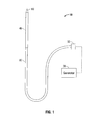
- Fig. 1 shows an embodiment of a microwave ablation system 10 in accordance with the present disclosure.
- the microwave ablation system 10 includes an electromagnetic surgical ablation probe 40 connected by a cable 30 to a connector 32, which may further operably connect the probe 40 to a generator assembly 20.
- Generator assembly 20 may include a source of ablation energy, e.g., microwave or RF energy in the range of about 500 MHz to about 5 GHz.
- Output stage 140 may be configured as a class B push-pull output stage having a complementary pair of transistors 142, 144.
- Transistor 142 may be an NPN transistor that is configured to supply current from supply rail 125 to an output load, e.g., a microwave ablation probe 105.
- Transistor 144 may be a PNP transistor that is configured to sink current from the output load to a ground rail 126.
- Ground rail 126 may be alternatively be configured as a negative supply rail.
- Amplifier 100 includes amplifier controller 110 that is configured to receive at least one sensor signal and in response thereto output at least one corresponding control signal to at least one of a rail voltage controller 120 and a drive controller 130.
- Amplifier controller 110 is operably coupled to at least one sensor 150 that is adapted to sense an electrical property of an output signal, e.g., voltage, current, impedance. Additionally or alternatively, sensor 150 may sense an instantaneous, peak, RMS, or moving average property of an output signal.
- Amplifier controller 110 may be configured to perform a method of controlling a push pull amplifier 100 as will be described in further detail hereinbelow.
- Rail voltage controller 120 is configured to provide a variable output voltage to supply rail 125 in response to a rail voltage control signal (not explicitly shown) received from amplifier controller 110.
- the rail voltage control signal may be any suitable signal, e.g., an analog or digital signal.
- Rail voltage controller 120 may include a power supply having a fixed or variable output voltage. It is envisioned that rail voltage controller 120 may encompass any suitable manner of voltage regulation, such as, and without limitation, an LM317 voltage regulator integrated circuit manufactured by National Semiconductor Corp. of Santa Clara, California, US.
- supply rail 125 is referenced to ground at return rail 126.
- Rail voltage controller 120 may be configured to provide a bipolar supply wherein e.g., a positive voltage is provided by rail voltage controller 120 to supply rail 125 and a negative voltage is provided by rail voltage controller 120 to return rail 126.
- Drive controller 130 is configured to provide an input signal to the output stage 140.
- Drive controller 130 may include an oscillator 134 configured to generate a radiofrequency ablation signal that is operable coupled to an output thereof to an attenuation network 136.
- drive controller 130 may include an RF signal input (not explicitly shown) that is operably coupled to an oscillator.
- Drive controller 130 includes a drive control input that is adapted to receive a drive control signal from amplifier controller 110.
- Attenuation network 136 is responsive to the drive control signal, whereby the drive control signal defines the degree of attenuation provided by attenuation network 136.
- Drive controller 130 may provide signal attenuation by any suitable manner of attenuation, for example, and without limitation, voltage-controlled amplifier (e.g., a unity gain voltage controlled amplifier), a digital potentiometer, or a digitally-switched voltage dividing network
- voltage-controlled amplifier e.g., a unity gain voltage controlled amplifier
- digital potentiometer e.g., a digital potentiometer
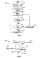
- a rail voltage control method 200 for operating push-pull amplifier 100 shows initial step 210 which is an entry point wherein initialization may be performed.
- the rail voltage and drive level are set to a minimum.
- amplifier controller 110 causes rail voltage controller 120 to output a minimum voltage, which may be in a range of about 0V to about 30V, e.g., 14V, and amplifier controller 110 may additionally or alternatively cause drive controller 130 to be set to a minimum drive level (i.e., maximum drive attenuation.)
- a desired output level is set, e.g., wherein a user selects a desired output level, which may be, for example and without limitation, an output voltage, output current, or other signal property.
- a main operational loop is entered wherein an output level is measured.
- amplifier controller 110 may poll an input thereof corresponding to an output of sensor 150.
- Sensor 150 may provide a signal to amplifier controller 110 in analog format, or in digital format.
- the step 225 may include an analog-to-digital conversion of the sensed output.
- the measured level is compared to the desired level to determine whether the output level equals the desired level. It is to be understood that comparisons performed by the methods disclosed herein may include a tolerance within which the values being compared are evaluated, e.g., quantities may be within a range and/or substantially equal to be deemed equal. If a positive determination is made (e.g., output level is acceptably equal to the desired level as described herein) the process iterates to the step 225.
- step 235 is performed wherein a determination is made whether the drive level is set to a maximum value (or alternatively, within a tolerance range of, or substantially equal to, a maximum value.) If it is determined the drive level is set to a maximum value (i.e., minimum drive attenuation), the step 245 is performed wherein the rail voltage is increased.
- a maximum value i.e., minimum drive attenuation
- the step 245 is performed wherein the rail voltage is increased.
- amplifier controller 110 causes rail voltage controller 120 to increase the output voltage thereof.
- the output voltage may be increased by a predetermined amount.
- step 245 the process iterates to step 225.
- step 240 is performed wherein the drive level is increased (i.e., drive attenuation is reduced). Subsequent to step 240, the process iterates to the step 225.
- step 240 or step 245 includes a time delay.
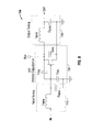
- an amplifier stage 300 includes a gain element 330, which may be a field effect transistor (FET), a gallium nitride (GaN) high electron mobility transistor (HEMTs), gallium arsenide (GaAs) FET, or a laterally diffused metal oxide semiconductor transistor (LDMOS), such as without limitation, a BLC6G10LS-160 as described hereinabove.
- FET field effect transistor
- GaN gallium nitride
- HEMTs gallium arsenide
- LDMOS laterally diffused metal oxide semiconductor transistor
- gain element 330 is an N channel device, such as a BLC6G10LS-160.
- Gain element 330 may alternatively be a P-channel device.
- Gate 331 of gain element 330 may be slightly biased at about 0.1A of the rail current.
- amplifier stage 300 includes a current sensor 310 that is adapted to measure a bias current of gain element 330 and communicate a value corresponding thereto to amplifier controller 110'.
- Amplifier 300 includes bias controller 320 that is in operable communication with amplifier controller 110'. Bias controller 320 is responsive to a bias control signal received from amplifier controller 110' to provide a bias current to gain element 330 in accordance with a method described below.
- a biasing method 400 for biasing a gain stage 300 begins at step 410 which is an entry point wherein initialization may be performed.
- the rail voltage is set to an initial value, which may be a minimum value, e.g., 14V.
- step 420 the rail current is measured and compared to a target current, e.g., 0.1A, to determine whether the rail current equals the target rail current. If the measured current does not equal the target current, step 425 is performed wherein the bias voltage is increased. In an embodiment, the bias voltage is increased by a fixed amount. Steps 420 and 425 are repeated iteratively until the rail current equals the target current.
- step 430 is performed wherein the bias voltage is stored.
- step 435 is then performed wherein the rail voltage is increased.
- a comparison is performed in step 440 to determine whether the rail voltage equals a maximum voltage. If the rail voltage equals a maximum voltage, the bias adjustment is complete and the process concludes in step 465.
- step 445 is performed wherein it is determined whether the rail current equals a target current value, e.g., 0.1A. If the rail current is determined to equal the target current, the process iterates at step 430 wherein the bias voltage is stored and the process continues as described herein. If the rail current does not equal the target current value, the rail current is tested in the step 450 to determine whether the rail current is less than the target current value. If it is determined the rail current is less than the target current value, the step 455 is performed wherein the bias voltage is increased, whereupon the process iterates to step 445. Conversely, if it is determined the rail current is not less than (e.g., greater than) the target current value, the step 460 is performed wherein the bias voltage is decreased, whereupon the process iterates to step 445.
- a target current value e.g., 0.1A
- the bias voltage is adjusted in an opposite manner, e.g., decreased in the step 455 and/or increased in the step 460, in accordance with the characteristics of a P-channel device.
- Fig. 7 illustrates a relationship between internal capacitances C iss , C oss , and C rss exhibited by a gain element, e.g., a FET, and a drain-to-source voltage V DS , e.g., a rail voltage.
- V DS drain-to-source voltage
- V DS e.g., the rail voltage
- the present disclosure contemplates a minimum rail voltage of about 14V.
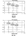
- FIG. 9A illustrates a graph of the power spectrum of a prior art single stage (class B) amplifier operating at 915 MHz at full power of about +52.55 dBm.
- a +9.341 dBm second harmonic is present at 1.83 GHz and a third harmonic of -12.63 dBm is present at 2.745 GHz.
- Fig. 9B illustrates an amplifier according to the present disclosure operating on a similar 915 MHz input signal as the Fig. 9A example.
- the Fig. 9B spectrum of the presently disclosed amplifier exhibits a second harmonic of 5.339 dBm, and a third harmonic of -27.32 dBm. This represents an improvement over the prior art of about a 4 dBm reduction in second-order harmonics and of about a 14.7 dBm reduction in third-order harmonics.
- FIG. 11A and 11B A comparison of harmonic performance at about half-power is illustrated with reference to Figs. 11A and 11B , which correspond to a prior art amplifier and an amplifier in accordance with the present disclosure, respectively.
- the present amplifier exhibits an improvement of about a 3 dBm reduction in second-order harmonics.
- Third-order harmonics increase about 12 dBm in the present amplifier.
- Fig. 10A is a graph representing a relationship between output power and efficiency to increasing input power level of a prior art amplifier
- Fig. 10B represents a relationship between output power and efficiency to increasing rail voltage of an amplifier according to the present invention.
- an amplifier according to the present invention exhibits a much higher and flatter efficiency curve than that of the prior art amplifier.
- a prior art amplifier at about 50% output power exhibits an efficiency of about 40%.
- an amplifier in accordance with the present disclosure at about 50% output power exhibits an efficiency of out 70%.
- the prior art amplifier has an efficiency which can be as low as 15%, while the efficiency of the presently disclosed amplifier never drops below 68% over an entire operating range thereof.
Landscapes
- Engineering & Computer Science (AREA)
- Power Engineering (AREA)
- Amplifiers (AREA)
- Surgical Instruments (AREA)
- Control Of Amplification And Gain Control (AREA)
- Microwave Amplifiers (AREA)
Applications Claiming Priority (1)
| Application Number | Priority Date | Filing Date | Title |
|---|---|---|---|
| US12/504,738 US7863984B1 (en) | 2009-07-17 | 2009-07-17 | High efficiency microwave amplifier |
Publications (3)
| Publication Number | Publication Date |
|---|---|
| EP2284989A2 true EP2284989A2 (de) | 2011-02-16 |
| EP2284989A3 EP2284989A3 (de) | 2017-04-26 |
| EP2284989B1 EP2284989B1 (de) | 2019-08-28 |
Family
ID=42983879
Family Applications (1)
| Application Number | Title | Priority Date | Filing Date |
|---|---|---|---|
| EP10007399.8A Active EP2284989B1 (de) | 2009-07-17 | 2010-07-16 | Hochleistungsmikrowellenverstärker |
Country Status (5)
| Country | Link |
|---|---|
| US (1) | US7863984B1 (de) |
| EP (1) | EP2284989B1 (de) |
| JP (1) | JP5599248B2 (de) |
| AU (1) | AU2010203036B2 (de) |
| CA (2) | CA2710048C (de) |
Families Citing this family (41)
| Publication number | Priority date | Publication date | Assignee | Title |
|---|---|---|---|---|
| US7553309B2 (en) | 2004-10-08 | 2009-06-30 | Covidien Ag | Electrosurgical system employing multiple electrodes and method thereof |
| US8323275B2 (en) | 2009-06-19 | 2012-12-04 | Vivant Medical, Inc. | Laparoscopic port with microwave rectifier |
| US8069553B2 (en) | 2009-09-09 | 2011-12-06 | Vivant Medical, Inc. | Method for constructing a dipole antenna |
| US9113925B2 (en) * | 2009-09-09 | 2015-08-25 | Covidien Lp | System and method for performing an ablation procedure |
| US9095359B2 (en) | 2009-09-18 | 2015-08-04 | Covidien Lp | Tissue ablation system with energy distribution |
| US9113926B2 (en) | 2009-09-29 | 2015-08-25 | Covidien Lp | Management of voltage standing wave ratio at skin surface during microwave ablation |
| US8568398B2 (en) | 2009-09-29 | 2013-10-29 | Covidien Lp | Flow rate monitor for fluid cooled microwave ablation probe |
| US8568401B2 (en) | 2009-10-27 | 2013-10-29 | Covidien Lp | System for monitoring ablation size |
| US8382750B2 (en) | 2009-10-28 | 2013-02-26 | Vivant Medical, Inc. | System and method for monitoring ablation size |
| US8430871B2 (en) | 2009-10-28 | 2013-04-30 | Covidien Lp | System and method for monitoring ablation size |
| US20110125148A1 (en) * | 2009-11-17 | 2011-05-26 | Turner Paul F | Multiple Frequency Energy Supply and Coagulation System |
| US8394092B2 (en) | 2009-11-17 | 2013-03-12 | Vivant Medical, Inc. | Electromagnetic energy delivery devices including an energy applicator array and electrosurgical systems including same |
| US8414570B2 (en) * | 2009-11-17 | 2013-04-09 | Bsd Medical Corporation | Microwave coagulation applicator and system |
| US9993294B2 (en) * | 2009-11-17 | 2018-06-12 | Perseon Corporation | Microwave coagulation applicator and system with fluid injection |
| US8551083B2 (en) | 2009-11-17 | 2013-10-08 | Bsd Medical Corporation | Microwave coagulation applicator and system |
| US8764744B2 (en) | 2010-01-25 | 2014-07-01 | Covidien Lp | System for monitoring ablation size |
| US8491579B2 (en) | 2010-02-05 | 2013-07-23 | Covidien Lp | Electrosurgical devices with choke shorted to biological tissue |
| US8968288B2 (en) | 2010-02-19 | 2015-03-03 | Covidien Lp | Ablation devices with dual operating frequencies, systems including same, and methods of adjusting ablation volume using same |
| US8617153B2 (en) | 2010-02-26 | 2013-12-31 | Covidien Lp | Tunable microwave ablation probe |
| US8728067B2 (en) | 2010-03-08 | 2014-05-20 | Covidien Lp | Microwave antenna probe having a deployable ground plane |
| US10039601B2 (en) | 2010-03-26 | 2018-08-07 | Covidien Lp | Ablation devices with adjustable radiating section lengths, electrosurgical systems including same, and methods of adjusting ablation fields using same |
| US8409188B2 (en) | 2010-03-26 | 2013-04-02 | Covidien Lp | Ablation devices with adjustable radiating section lengths, electrosurgical systems including same, and methods of adjusting ablation fields using same |
| US9192436B2 (en) | 2010-05-25 | 2015-11-24 | Covidien Lp | Flow rate verification monitor for fluid-cooled microwave ablation probe |
| US8652127B2 (en) | 2010-05-26 | 2014-02-18 | Covidien Lp | System and method for chemically cooling an ablation antenna |
| US8672933B2 (en) | 2010-06-30 | 2014-03-18 | Covidien Lp | Microwave antenna having a reactively-loaded loop configuration |
| US10588684B2 (en) | 2010-07-19 | 2020-03-17 | Covidien Lp | Hydraulic conductivity monitoring to initiate tissue division |
| US9028476B2 (en) | 2011-02-03 | 2015-05-12 | Covidien Lp | Dual antenna microwave resection and ablation device, system and method of use |
| US9033970B2 (en) | 2011-09-20 | 2015-05-19 | Covidien Lp | Handheld medical devices including microwave amplifier unit at device handle |
| US9039693B2 (en) | 2011-09-20 | 2015-05-26 | Covidien Lp | Handheld medical devices including microwave amplifier unit at device handle |
| US9039692B2 (en) | 2011-09-20 | 2015-05-26 | Covidien Lp | Handheld medical devices including microwave amplifier unit at device handle |
| US8745846B2 (en) * | 2011-09-20 | 2014-06-10 | Covidien Lp | Method of manufacturing handheld medical devices including microwave amplifier unit |
| US9023025B2 (en) | 2011-09-20 | 2015-05-05 | Covidien Lp | Handheld medical devices including microwave amplifier unit at device handle |
| US9872719B2 (en) | 2013-07-24 | 2018-01-23 | Covidien Lp | Systems and methods for generating electrosurgical energy using a multistage power converter |
| US9636165B2 (en) | 2013-07-29 | 2017-05-02 | Covidien Lp | Systems and methods for measuring tissue impedance through an electrosurgical cable |
| US11065053B2 (en) | 2016-08-02 | 2021-07-20 | Covidien Lp | Ablation cable assemblies and a method of manufacturing the same |
| US11197715B2 (en) | 2016-08-02 | 2021-12-14 | Covidien Lp | Ablation cable assemblies and a method of manufacturing the same |
| US10376309B2 (en) | 2016-08-02 | 2019-08-13 | Covidien Lp | Ablation cable assemblies and a method of manufacturing the same |
| WO2018126247A2 (en) * | 2017-01-02 | 2018-07-05 | Mojoose, Inc. | Automatic signal strength indicator and automatic antenna switch |
| AU2018381241B2 (en) * | 2017-12-06 | 2024-11-21 | Stryker Corporation | System and methods for controlling patient leakage current in a surgical system |
| US10756675B2 (en) * | 2018-11-28 | 2020-08-25 | Qorvo Us, Inc. | Broadband power amplifier circuit |
| US12226143B2 (en) | 2020-06-22 | 2025-02-18 | Covidien Lp | Universal surgical footswitch toggling |
Family Cites Families (105)
| Publication number | Priority date | Publication date | Assignee | Title |
|---|---|---|---|---|
| DE390937C (de) | 1922-10-13 | 1924-03-03 | Adolf Erb | Vorrichtung zur Innenbeheizung von Wannenoefen zum Haerten, Anlassen, Gluehen, Vergueten und Schmelzen |
| DE1099658B (de) | 1959-04-29 | 1961-02-16 | Siemens Reiniger Werke Ag | Selbsttaetige Einschaltvorrichtung fuer Hochfrequenzchirurgiegeraete |
| FR1275415A (fr) | 1960-09-26 | 1961-11-10 | Dispositif détecteur de perturbations pour installations électriques, notamment d'électrochirurgie | |
| DE1139927B (de) | 1961-01-03 | 1962-11-22 | Friedrich Laber | Hochfrequenz-Chirurgiegeraet |
| DE1149832C2 (de) | 1961-02-25 | 1977-10-13 | Siemens AG, 1000 Berlin und 8000 München | Hochfrequenz-chirurgieapparat |
| FR1347865A (fr) | 1962-11-22 | 1964-01-04 | Perfectionnements aux appareils de diathermo-coagulation | |
| DE1439302B2 (de) | 1963-10-26 | 1971-05-19 | Siemens AG, 1000 Berlin u 8000 München | Hochfrequenz Chirurgiegerat |
| SU401367A1 (ru) | 1971-10-05 | 1973-10-12 | Тернопольский государственный медицинский институт | Биактивный электрохирургическнп инструмент |
| FR2235669A1 (en) | 1973-07-07 | 1975-01-31 | Lunacek Boris | Gynaecological sterilisation instrument - has hollow electrode protruding from the end of a curved ended tube |
| GB1480736A (en) | 1973-08-23 | 1977-07-20 | Matburn Ltd | Electrodiathermy apparatus |
| DE2455174A1 (de) | 1973-11-21 | 1975-05-22 | Termiflex Corp | Ein/ausgabegeraet zum datenaustausch mit datenverarbeitungseinrichtungen |
| DE2407559C3 (de) | 1974-02-16 | 1982-01-21 | Dornier System Gmbh, 7990 Friedrichshafen | Wärmesonde |
| DE2415263A1 (de) | 1974-03-29 | 1975-10-02 | Aesculap Werke Ag | Chirurgische hf-koagulationssonde |
| DE2429021C2 (de) | 1974-06-18 | 1983-12-08 | Erbe Elektromedizin GmbH, 7400 Tübingen | Fernschalteinrichtung für ein HF-Chirurgiegerät |
| FR2276027A1 (fr) | 1974-06-25 | 1976-01-23 | Medical Plastics Inc | Raccordement electrique pour electrode plane |
| DE2460481A1 (de) | 1974-12-20 | 1976-06-24 | Delma Elektro Med App | Elektrodenhandgriff zur handfernschaltung eines hochfrequenz-chirurgiegeraets |
| US4237887A (en) | 1975-01-23 | 1980-12-09 | Valleylab, Inc. | Electrosurgical device |
| DE2504280C3 (de) | 1975-02-01 | 1980-08-28 | Hans Heinrich Prof. Dr. 8035 Gauting Meinke | Vorrichtung zum Schneiden und/oder Koagulieren menschlichen Gewebes mit Hochfrequenzstrom |
| CA1064581A (en) | 1975-06-02 | 1979-10-16 | Stephen W. Andrews | Pulse control circuit and method for electrosurgical units |
| FR2315286A2 (fr) | 1975-06-26 | 1977-01-21 | Lamidey Marcel | Pince a dissequer, hemostatique, haute frequence |
| DE2540968C2 (de) | 1975-09-13 | 1982-12-30 | Erbe Elektromedizin GmbH, 7400 Tübingen | Einrichtung zum Einschalten des Koagulationsstroms einer bipolaren Koagulationspinzette |
| FR2390968A1 (fr) | 1977-05-16 | 1978-12-15 | Skovajsa Joseph | Dispositif de traitement local d'un patient, notamment pour acupuncture ou auriculotherapie |
| SU727201A2 (ru) | 1977-11-02 | 1980-04-15 | Киевский Научно-Исследовательский Институт Нейрохирургии | Электрохирургический аппарат |
| DE2803275C3 (de) | 1978-01-26 | 1980-09-25 | Aesculap-Werke Ag Vormals Jetter & Scheerer, 7200 Tuttlingen | Fernschalteinrichtung zum Schalten eines monopolaren HF-Chirurgiegerätes |
| DE2823291A1 (de) | 1978-05-27 | 1979-11-29 | Rainer Ing Grad Koch | Schaltung zur automatischen einschaltung des hochfrequenzstromes von hochfrequenz-koagulationsgeraeten |
| US4296413A (en) | 1979-09-28 | 1981-10-20 | General Electric Company | Resistance-bridge to frequency converter with automatic offset correction |
| DE2946728A1 (de) | 1979-11-20 | 1981-05-27 | Erbe Elektromedizin GmbH & Co KG, 7400 Tübingen | Hochfrequenz-chirurgiegeraet |
| JPS5778844A (en) | 1980-11-04 | 1982-05-17 | Kogyo Gijutsuin | Lasre knife |
| DE3045996A1 (de) | 1980-12-05 | 1982-07-08 | Medic Eschmann Handelsgesellschaft für medizinische Instrumente mbH, 2000 Hamburg | Elektro-chirurgiegeraet |
| FR2502935B1 (fr) | 1981-03-31 | 1985-10-04 | Dolley Roger | Procede et dispositif de controle de la coagulation de tissus a l'aide d'un courant a haute frequence |
| DE3120102A1 (de) | 1981-05-20 | 1982-12-09 | F.L. Fischer GmbH & Co, 7800 Freiburg | Anordnung zur hochfrequenzkoagulation von eiweiss fuer chirurgische zwecke |
| US4438766A (en) | 1981-09-03 | 1984-03-27 | C. R. Bard, Inc. | Electrosurgical generator |
| US4559943A (en) | 1981-09-03 | 1985-12-24 | C. R. Bard, Inc. | Electrosurgical generator |
| FR2517953A1 (fr) | 1981-12-10 | 1983-06-17 | Alvar Electronic | Appareil diaphanometre et son procede d'utilisation |
| FR2573301B3 (fr) | 1984-11-16 | 1987-04-30 | Lamidey Gilles | Pince chirurgicale et son appareillage de commande et de controle |
| DE3510586A1 (de) | 1985-03-23 | 1986-10-02 | Erbe Elektromedizin GmbH, 7400 Tübingen | Kontrolleinrichtung fuer ein hochfrequenz-chirurgiegeraet |
| DE3604823C2 (de) | 1986-02-15 | 1995-06-01 | Lindenmeier Heinz | Hochfrequenzgenerator mit automatischer Leistungsregelung für die Hochfrequenzchirurgie |
| EP0246350A1 (de) | 1986-05-23 | 1987-11-25 | Erbe Elektromedizin GmbH. | Koagulationselektrode |
| DE3711511C1 (de) | 1987-04-04 | 1988-06-30 | Hartmann & Braun Ag | Verfahren zur Bestimmung der Gaskonzentrationen in einem Gasgemisch und Sensor zur Messung der Waermeleitfaehigkeit |
| DE8712328U1 (de) | 1987-09-11 | 1988-02-18 | Jakoubek, Franz, 7201 Emmingen-Liptingen | Endoskopiezange |
| DE3904558C2 (de) | 1989-02-15 | 1997-09-18 | Lindenmeier Heinz | Automatisch leistungsgeregelter Hochfrequenzgenerator für die Hochfrequenz-Chirurgie |
| US5531774A (en) | 1989-09-22 | 1996-07-02 | Alfred E. Mann Foundation For Scientific Research | Multichannel implantable cochlear stimulator having programmable bipolar, monopolar or multipolar electrode configurations |
| DE3942998C2 (de) | 1989-12-27 | 1998-11-26 | Delma Elektro Med App | Elektrochirurgisches Hochfrequenzgerät |
| JP2806511B2 (ja) | 1990-07-31 | 1998-09-30 | 松下電工株式会社 | 合金系焼結体の製法 |
| US5221269A (en) | 1990-10-15 | 1993-06-22 | Cook Incorporated | Guide for localizing a nonpalpable breast lesion |
| JP2951418B2 (ja) | 1991-02-08 | 1999-09-20 | トキコ株式会社 | 試料液成分分析装置 |
| DE4122050C2 (de) | 1991-07-03 | 1996-05-30 | Gore W L & Ass Gmbh | Antennenanordnung mit Zuleitung zur medizinischen Wärmeapplikation in Körperhohlräumen |
| US5366477A (en) | 1991-10-17 | 1994-11-22 | American Cyanamid Company | Actuating forces transmission link and assembly for use in surgical instruments |
| DE4238263A1 (en) | 1991-11-15 | 1993-05-19 | Minnesota Mining & Mfg | Adhesive comprising hydrogel and crosslinked polyvinyl:lactam - is used in electrodes for biomedical application providing low impedance and good mechanical properties when water and/or moisture is absorbed from skin |
| DE4205213A1 (de) | 1992-02-20 | 1993-08-26 | Delma Elektro Med App | Hochfrequenzchirurgiegeraet |
| FR2687786B1 (fr) | 1992-02-26 | 1994-05-06 | Pechiney Recherche | Mesure de la resistivite electrique et de la conductivite thermique a haute temperature de produits refractaires. |
| EP0558051B1 (de) | 1992-02-27 | 1996-10-16 | FISHER & PAYKEL LIMITED | Kabelendstück-Zustandsdetektion |
| CA2094220A1 (en) | 1992-05-21 | 1993-11-22 | Mark A. Rydell | Surgical scissors with bipolar coagulation feature |
| DE4303882C2 (de) | 1993-02-10 | 1995-02-09 | Kernforschungsz Karlsruhe | Kombinationsinstrument zum Trennen und Koagulieren für die minimal invasive Chirurgie |
| GB9309142D0 (en) | 1993-05-04 | 1993-06-16 | Gyrus Medical Ltd | Laparoscopic instrument |
| GB9314391D0 (en) | 1993-07-12 | 1993-08-25 | Gyrus Medical Ltd | A radio frequency oscillator and an electrosurgical generator incorporating such an oscillator |
| US5381115A (en) * | 1993-08-30 | 1995-01-10 | Hughes Aircraft Company | Method and apparatus for regulating output power of signal amplifier |
| GB9322464D0 (en) | 1993-11-01 | 1993-12-22 | Gyrus Medical Ltd | Electrosurgical apparatus |
| DE4339049C2 (de) | 1993-11-16 | 2001-06-28 | Erbe Elektromedizin | Einrichtung zur Konfiguration chirurgischer Systeme |
| GB9413070D0 (en) | 1994-06-29 | 1994-08-17 | Gyrus Medical Ltd | Electrosurgical apparatus |
| GB9425781D0 (en) | 1994-12-21 | 1995-02-22 | Gyrus Medical Ltd | Electrosurgical instrument |
| US6293942B1 (en) | 1995-06-23 | 2001-09-25 | Gyrus Medical Limited | Electrosurgical generator method |
| JPH0966058A (ja) * | 1995-08-31 | 1997-03-11 | Olympus Optical Co Ltd | 高周波電気メス装置 |
| DE19535868A1 (de) * | 1995-09-27 | 1997-04-03 | Thomson Brandt Gmbh | Schaltung zur Stromversorgung mehrerer Leistungsverstärker |
| DE19608716C1 (de) | 1996-03-06 | 1997-04-17 | Aesculap Ag | Bipolares chirurgisches Faßinstrument |
| US6017354A (en) | 1996-08-15 | 2000-01-25 | Stryker Corporation | Integrated system for powered surgical tools |
| US5836943A (en) * | 1996-08-23 | 1998-11-17 | Team Medical, L.L.C. | Electrosurgical generator |
| DE29616210U1 (de) | 1996-09-18 | 1996-11-14 | Olympus Winter & Ibe Gmbh, 22045 Hamburg | Handhabe für chirurgische Instrumente |
| DE19643127A1 (de) | 1996-10-18 | 1998-04-23 | Berchtold Gmbh & Co Geb | Hochfrequenzchirurgiegerät und Verfahren zu dessen Betrieb |
| US5830212A (en) | 1996-10-21 | 1998-11-03 | Ndm, Inc. | Electrosurgical generator and electrode |
| US5923475A (en) | 1996-11-27 | 1999-07-13 | Eastman Kodak Company | Laser printer using a fly's eye integrator |
| GB9626512D0 (en) * | 1996-12-20 | 1997-02-05 | Gyrus Medical Ltd | An improved electrosurgical generator and system |
| GB9708268D0 (en) | 1997-04-24 | 1997-06-18 | Gyrus Medical Ltd | An electrosurgical instrument |
| DE19717411A1 (de) | 1997-04-25 | 1998-11-05 | Aesculap Ag & Co Kg | Verfahren und Vorrichtung zur Überwachung der thermischen Belastung des Gewebes eines Patienten |
| DE19751108A1 (de) | 1997-11-18 | 1999-05-20 | Beger Frank Michael Dipl Desig | Elektrochirurgisches Operationswerkzeug |
| EP0923907A1 (de) | 1997-12-19 | 1999-06-23 | Gyrus Medical Limited | Elektrochirurgisches Instrument |
| DE19801173C1 (de) | 1998-01-15 | 1999-07-15 | Kendall Med Erzeugnisse Gmbh | Klemmverbinder für Filmelektroden |
| JP3597391B2 (ja) * | 1998-07-30 | 2004-12-08 | オリンパス株式会社 | 電気外科手術装置 |
| JP2000041995A (ja) * | 1998-07-31 | 2000-02-15 | Olympus Optical Co Ltd | 電気手術装置 |
| DE19848540A1 (de) | 1998-10-21 | 2000-05-25 | Reinhard Kalfhaus | Schaltungsanordnung und Verfahren zum Betreiben eines Wechselrichters |
| JP3910750B2 (ja) * | 1999-02-26 | 2007-04-25 | オリンパス株式会社 | 電気外科手術装置 |
| GB9911954D0 (en) | 1999-05-21 | 1999-07-21 | Gyrus Medical Ltd | Electrosurgery system and instrument |
| GB9911956D0 (en) | 1999-05-21 | 1999-07-21 | Gyrus Medical Ltd | Electrosurgery system and method |
| GB9912625D0 (en) | 1999-05-28 | 1999-07-28 | Gyrus Medical Ltd | An electrosurgical generator and system |
| GB9912627D0 (en) | 1999-05-28 | 1999-07-28 | Gyrus Medical Ltd | An electrosurgical instrument |
| GB9913652D0 (en) | 1999-06-11 | 1999-08-11 | Gyrus Medical Ltd | An electrosurgical generator |
| US6723091B2 (en) | 2000-02-22 | 2004-04-20 | Gyrus Medical Limited | Tissue resurfacing |
| US7300436B2 (en) | 2000-02-22 | 2007-11-27 | Rhytec Limited | Tissue resurfacing |
| US6498466B1 (en) | 2000-05-23 | 2002-12-24 | Linear Technology Corp. | Cancellation of slope compensation effect on current limit |
| DE10027727C1 (de) | 2000-06-03 | 2001-12-06 | Aesculap Ag & Co Kg | Scheren- oder zangenförmiges chirurgisches Instrument |
| US6639471B2 (en) * | 2001-04-16 | 2003-10-28 | Matsushita Electric Industrial Co., Ltd. | Power amplifier circuit, control method for power amplifier circuit, and portable terminal apparatus for mobile communication |
| US6624702B1 (en) * | 2002-04-05 | 2003-09-23 | Rf Micro Devices, Inc. | Automatic Vcc control for optimum power amplifier efficiency |
| US6720831B2 (en) * | 2002-04-26 | 2004-04-13 | Rf Micro Devices, Inc. | Power amplifier protection circuit |
| DE10224154A1 (de) | 2002-05-27 | 2003-12-18 | Celon Ag Medical Instruments | Vorrichtung zum elektrochirurgischen Veröden von Körpergewebe |
| DE60314184T2 (de) | 2003-01-09 | 2008-01-24 | Gyrus Medical Ltd., St. Mellons | Elektrochirurgischer generator |
| US7195627B2 (en) | 2003-01-09 | 2007-03-27 | Gyrus Medical Limited | Electrosurgical generator |
| DE10328514B3 (de) | 2003-06-20 | 2005-03-03 | Aesculap Ag & Co. Kg | Chirurgisches Instrument |
| JP2005102750A (ja) * | 2003-09-26 | 2005-04-21 | Olympus Corp | 電気手術用電源装置 |
| FR2862813B1 (fr) | 2003-11-20 | 2006-06-02 | Pellenc Sa | Procede de chargement equilibre d'une batterie lithium-ion ou lithium polymere |
| FR2864439B1 (fr) | 2003-12-30 | 2010-12-03 | Image Guided Therapy | Dispositif de traitement d'un volume de tissu biologique par hyperthermie localisee |
| DE102004022206B4 (de) | 2004-05-04 | 2006-05-11 | Bundesrepublik Deutschland, vertr. d. d. Bundesministerium für Wirtschaft und Arbeit, dieses vertr. d. d. Präsidenten der Physikalisch-Technischen Bundesanstalt | Sensor und Sensoranordnung zur Messung der Wärmeleitfähigkeit einer Probe |
| US7193459B1 (en) * | 2004-06-23 | 2007-03-20 | Rf Micro Devices, Inc. | Power amplifier control technique for enhanced efficiency |
| US7422582B2 (en) | 2004-09-29 | 2008-09-09 | Stryker Corporation | Control console to which powered surgical handpieces are connected, the console configured to simultaneously energize more than one and less than all of the handpieces |
| US7190221B2 (en) * | 2004-10-22 | 2007-03-13 | Nokia Corporation | Method and apparatus for maintaining constant linearity for a power amplifier over varying load conditions |
| DE202005015147U1 (de) | 2005-09-26 | 2006-02-09 | Health & Life Co., Ltd., Chung-Ho | Biosensor-Teststreifen mit Identifizierfunktion |
-
2009
- 2009-07-17 US US12/504,738 patent/US7863984B1/en active Active
-
2010
- 2010-07-16 AU AU2010203036A patent/AU2010203036B2/en not_active Ceased
- 2010-07-16 EP EP10007399.8A patent/EP2284989B1/de active Active
- 2010-07-16 CA CA2710048A patent/CA2710048C/en not_active Expired - Fee Related
- 2010-07-16 JP JP2010161455A patent/JP5599248B2/ja not_active Expired - Fee Related
- 2010-07-16 CA CA3014143A patent/CA3014143C/en not_active Expired - Fee Related
Non-Patent Citations (1)
| Title |
|---|
| None |
Also Published As
| Publication number | Publication date |
|---|---|
| CA3014143A1 (en) | 2011-01-17 |
| US7863984B1 (en) | 2011-01-04 |
| EP2284989A3 (de) | 2017-04-26 |
| EP2284989B1 (de) | 2019-08-28 |
| CA3014143C (en) | 2021-10-19 |
| AU2010203036B2 (en) | 2013-10-31 |
| CA2710048C (en) | 2018-09-25 |
| JP2011041265A (ja) | 2011-02-24 |
| AU2010203036A1 (en) | 2011-02-03 |
| JP5599248B2 (ja) | 2014-10-01 |
| US20110012679A1 (en) | 2011-01-20 |
| CA2710048A1 (en) | 2011-01-17 |
Similar Documents
| Publication | Publication Date | Title |
|---|---|---|
| US7863984B1 (en) | High efficiency microwave amplifier | |
| Wright et al. | An efficient, linear, broadband class-J-mode PA realised using RF waveform engineering | |
| US7295064B2 (en) | Doherty amplifier | |
| Carrubba et al. | A novel highly efficient broadband continuous class-F RFPA delivering 74% average efficiency for an octave bandwidth | |
| KR101145666B1 (ko) | 고주파용 3-스테이지 질화 갈륨계 고전자 이동도 트랜지스터(GaN HEMT) 도허티 전력증폭기 | |
| US7986186B2 (en) | Adaptive bias technique for field effect transistor | |
| US20190097588A1 (en) | Systems and Methods for Optimizing Amplifier Operations | |
| CN110784184B (zh) | 宽带大功率放大器 | |
| US20040075504A1 (en) | Method and arrangement for detecting load mismatch, and a radio device utilizing the same | |
| JPWO2013054601A1 (ja) | フロントエンド増幅器 | |
| KR101683285B1 (ko) | 포화 동작을 사용하는 고효율 전력 증폭 장치 및 그 제어 방법 | |
| Kim et al. | Ka-band cascode CMOS power amplifier with improved linearity using bias optimization technique | |
| Wolff et al. | Challenges in the design of wideband GaN-HEMT based class-G RF-power amplifiers | |
| Sira et al. | Output power control in class-E power amplifiers | |
| Markos et al. | A 50 W unsymmetrical GaN Doherty amplifier for LTE applications | |
| CN103944520B (zh) | 电流源电路及射频信号放大系统 | |
| Monprasert et al. | 2.45 GHz GaN HEMT Class-AB RF power amplifier design for wireless communication systems | |
| Zhang et al. | A 550–1050MHz+ 30dBm class-E power amplifier in 65nm CMOS | |
| Sajedin et al. | A Doherty power amplifier based on the harmonic generating mechanism | |
| Mimis et al. | A reactively load-modulated RF low-power amplifier with multilevel supply voltage for multi-standard RF front-ends | |
| Mimis et al. | Impact of time misalignment and input signal statistics in dynamically load-modulated amplifiers | |
| US12160202B2 (en) | Amplifying device | |
| Lasser et al. | Independent dynamic gate bias for a two-stage amplifier for amplitude and phase linearization | |
| Jędrzejewski et al. | Impact evaluation of DC operating condition on DPD linearizability and power efficiency in GaN-based power amplifiers | |
| CN111194109B (zh) | 微波加热组件和微波加热设备 |
Legal Events
| Date | Code | Title | Description |
|---|---|---|---|
| PUAI | Public reference made under article 153(3) epc to a published international application that has entered the european phase |
Free format text: ORIGINAL CODE: 0009012 |
|
| AK | Designated contracting states |
Kind code of ref document: A2 Designated state(s): AL AT BE BG CH CY CZ DE DK EE ES FI FR GB GR HR HU IE IS IT LI LT LU LV MC MK MT NL NO PL PT RO SE SI SK SM TR |
|
| AX | Request for extension of the european patent |
Extension state: BA ME RS |
|
| RAP1 | Party data changed (applicant data changed or rights of an application transferred) |
Owner name: VIVANT MEDICAL, INC. |
|
| RAP1 | Party data changed (applicant data changed or rights of an application transferred) |
Owner name: COVIDIEN LP |
|
| RIC1 | Information provided on ipc code assigned before grant |
Ipc: H03F 1/02 20060101AFI20161219BHEP Ipc: H03F 3/26 20060101ALI20161219BHEP Ipc: H03F 3/19 20060101ALI20161219BHEP |
|
| PUAL | Search report despatched |
Free format text: ORIGINAL CODE: 0009013 |
|
| AK | Designated contracting states |
Kind code of ref document: A3 Designated state(s): AL AT BE BG CH CY CZ DE DK EE ES FI FR GB GR HR HU IE IS IT LI LT LU LV MC MK MT NL NO PL PT RO SE SI SK SM TR |
|
| AX | Request for extension of the european patent |
Extension state: BA ME RS |
|
| RIC1 | Information provided on ipc code assigned before grant |
Ipc: H03F 1/02 20060101AFI20170320BHEP Ipc: H03F 3/26 20060101ALI20170320BHEP Ipc: H03F 3/19 20060101ALI20170320BHEP |
|
| STAA | Information on the status of an ep patent application or granted ep patent |
Free format text: STATUS: REQUEST FOR EXAMINATION WAS MADE |
|
| 17P | Request for examination filed |
Effective date: 20171025 |
|
| RBV | Designated contracting states (corrected) |
Designated state(s): AL AT BE BG CH CY CZ DE DK EE ES FI FR GB GR HR HU IE IS IT LI LT LU LV MC MK MT NL NO PL PT RO SE SI SK SM TR |
|
| GRAP | Despatch of communication of intention to grant a patent |
Free format text: ORIGINAL CODE: EPIDOSNIGR1 |
|
| STAA | Information on the status of an ep patent application or granted ep patent |
Free format text: STATUS: GRANT OF PATENT IS INTENDED |
|
| INTG | Intention to grant announced |
Effective date: 20190321 |
|
| GRAS | Grant fee paid |
Free format text: ORIGINAL CODE: EPIDOSNIGR3 |
|
| GRAA | (expected) grant |
Free format text: ORIGINAL CODE: 0009210 |
|
| STAA | Information on the status of an ep patent application or granted ep patent |
Free format text: STATUS: THE PATENT HAS BEEN GRANTED |
|
| AK | Designated contracting states |
Kind code of ref document: B1 Designated state(s): AL AT BE BG CH CY CZ DE DK EE ES FI FR GB GR HR HU IE IS IT LI LT LU LV MC MK MT NL NO PL PT RO SE SI SK SM TR |
|
| REG | Reference to a national code |
Ref country code: GB Ref legal event code: FG4D |
|
| REG | Reference to a national code |
Ref country code: CH Ref legal event code: EP |
|
| REG | Reference to a national code |
Ref country code: AT Ref legal event code: REF Ref document number: 1173657 Country of ref document: AT Kind code of ref document: T Effective date: 20190915 |
|
| REG | Reference to a national code |
Ref country code: IE Ref legal event code: FG4D |
|
| REG | Reference to a national code |
Ref country code: DE Ref legal event code: R096 Ref document number: 602010060737 Country of ref document: DE |
|
| REG | Reference to a national code |
Ref country code: NL Ref legal event code: MP Effective date: 20190828 |
|
| REG | Reference to a national code |
Ref country code: LT Ref legal event code: MG4D |
|
| PG25 | Lapsed in a contracting state [announced via postgrant information from national office to epo] |
Ref country code: FI Free format text: LAPSE BECAUSE OF FAILURE TO SUBMIT A TRANSLATION OF THE DESCRIPTION OR TO PAY THE FEE WITHIN THE PRESCRIBED TIME-LIMIT Effective date: 20190828 Ref country code: PT Free format text: LAPSE BECAUSE OF FAILURE TO SUBMIT A TRANSLATION OF THE DESCRIPTION OR TO PAY THE FEE WITHIN THE PRESCRIBED TIME-LIMIT Effective date: 20191230 Ref country code: NO Free format text: LAPSE BECAUSE OF FAILURE TO SUBMIT A TRANSLATION OF THE DESCRIPTION OR TO PAY THE FEE WITHIN THE PRESCRIBED TIME-LIMIT Effective date: 20191128 Ref country code: HR Free format text: LAPSE BECAUSE OF FAILURE TO SUBMIT A TRANSLATION OF THE DESCRIPTION OR TO PAY THE FEE WITHIN THE PRESCRIBED TIME-LIMIT Effective date: 20190828 Ref country code: LT Free format text: LAPSE BECAUSE OF FAILURE TO SUBMIT A TRANSLATION OF THE DESCRIPTION OR TO PAY THE FEE WITHIN THE PRESCRIBED TIME-LIMIT Effective date: 20190828 Ref country code: BG Free format text: LAPSE BECAUSE OF FAILURE TO SUBMIT A TRANSLATION OF THE DESCRIPTION OR TO PAY THE FEE WITHIN THE PRESCRIBED TIME-LIMIT Effective date: 20191128 Ref country code: SE Free format text: LAPSE BECAUSE OF FAILURE TO SUBMIT A TRANSLATION OF THE DESCRIPTION OR TO PAY THE FEE WITHIN THE PRESCRIBED TIME-LIMIT Effective date: 20190828 Ref country code: NL Free format text: LAPSE BECAUSE OF FAILURE TO SUBMIT A TRANSLATION OF THE DESCRIPTION OR TO PAY THE FEE WITHIN THE PRESCRIBED TIME-LIMIT Effective date: 20190828 |
|
| PG25 | Lapsed in a contracting state [announced via postgrant information from national office to epo] |
Ref country code: AL Free format text: LAPSE BECAUSE OF FAILURE TO SUBMIT A TRANSLATION OF THE DESCRIPTION OR TO PAY THE FEE WITHIN THE PRESCRIBED TIME-LIMIT Effective date: 20190828 Ref country code: GR Free format text: LAPSE BECAUSE OF FAILURE TO SUBMIT A TRANSLATION OF THE DESCRIPTION OR TO PAY THE FEE WITHIN THE PRESCRIBED TIME-LIMIT Effective date: 20191129 Ref country code: IS Free format text: LAPSE BECAUSE OF FAILURE TO SUBMIT A TRANSLATION OF THE DESCRIPTION OR TO PAY THE FEE WITHIN THE PRESCRIBED TIME-LIMIT Effective date: 20191228 Ref country code: LV Free format text: LAPSE BECAUSE OF FAILURE TO SUBMIT A TRANSLATION OF THE DESCRIPTION OR TO PAY THE FEE WITHIN THE PRESCRIBED TIME-LIMIT Effective date: 20190828 Ref country code: ES Free format text: LAPSE BECAUSE OF FAILURE TO SUBMIT A TRANSLATION OF THE DESCRIPTION OR TO PAY THE FEE WITHIN THE PRESCRIBED TIME-LIMIT Effective date: 20190828 |
|
| REG | Reference to a national code |
Ref country code: AT Ref legal event code: MK05 Ref document number: 1173657 Country of ref document: AT Kind code of ref document: T Effective date: 20190828 |
|
| PG25 | Lapsed in a contracting state [announced via postgrant information from national office to epo] |
Ref country code: TR Free format text: LAPSE BECAUSE OF FAILURE TO SUBMIT A TRANSLATION OF THE DESCRIPTION OR TO PAY THE FEE WITHIN THE PRESCRIBED TIME-LIMIT Effective date: 20190828 |
|
| PG25 | Lapsed in a contracting state [announced via postgrant information from national office to epo] |
Ref country code: RO Free format text: LAPSE BECAUSE OF FAILURE TO SUBMIT A TRANSLATION OF THE DESCRIPTION OR TO PAY THE FEE WITHIN THE PRESCRIBED TIME-LIMIT Effective date: 20190828 Ref country code: IT Free format text: LAPSE BECAUSE OF FAILURE TO SUBMIT A TRANSLATION OF THE DESCRIPTION OR TO PAY THE FEE WITHIN THE PRESCRIBED TIME-LIMIT Effective date: 20190828 Ref country code: PL Free format text: LAPSE BECAUSE OF FAILURE TO SUBMIT A TRANSLATION OF THE DESCRIPTION OR TO PAY THE FEE WITHIN THE PRESCRIBED TIME-LIMIT Effective date: 20190828 Ref country code: AT Free format text: LAPSE BECAUSE OF FAILURE TO SUBMIT A TRANSLATION OF THE DESCRIPTION OR TO PAY THE FEE WITHIN THE PRESCRIBED TIME-LIMIT Effective date: 20190828 Ref country code: DK Free format text: LAPSE BECAUSE OF FAILURE TO SUBMIT A TRANSLATION OF THE DESCRIPTION OR TO PAY THE FEE WITHIN THE PRESCRIBED TIME-LIMIT Effective date: 20190828 Ref country code: EE Free format text: LAPSE BECAUSE OF FAILURE TO SUBMIT A TRANSLATION OF THE DESCRIPTION OR TO PAY THE FEE WITHIN THE PRESCRIBED TIME-LIMIT Effective date: 20190828 |
|
| PG25 | Lapsed in a contracting state [announced via postgrant information from national office to epo] |
Ref country code: CZ Free format text: LAPSE BECAUSE OF FAILURE TO SUBMIT A TRANSLATION OF THE DESCRIPTION OR TO PAY THE FEE WITHIN THE PRESCRIBED TIME-LIMIT Effective date: 20190828 Ref country code: SM Free format text: LAPSE BECAUSE OF FAILURE TO SUBMIT A TRANSLATION OF THE DESCRIPTION OR TO PAY THE FEE WITHIN THE PRESCRIBED TIME-LIMIT Effective date: 20190828 Ref country code: SK Free format text: LAPSE BECAUSE OF FAILURE TO SUBMIT A TRANSLATION OF THE DESCRIPTION OR TO PAY THE FEE WITHIN THE PRESCRIBED TIME-LIMIT Effective date: 20190828 Ref country code: IS Free format text: LAPSE BECAUSE OF FAILURE TO SUBMIT A TRANSLATION OF THE DESCRIPTION OR TO PAY THE FEE WITHIN THE PRESCRIBED TIME-LIMIT Effective date: 20200224 |
|
| REG | Reference to a national code |
Ref country code: DE Ref legal event code: R097 Ref document number: 602010060737 Country of ref document: DE |
|
| PLBE | No opposition filed within time limit |
Free format text: ORIGINAL CODE: 0009261 |
|
| STAA | Information on the status of an ep patent application or granted ep patent |
Free format text: STATUS: NO OPPOSITION FILED WITHIN TIME LIMIT |
|
| PG2D | Information on lapse in contracting state deleted |
Ref country code: IS |
|
| 26N | No opposition filed |
Effective date: 20200603 |
|
| PG25 | Lapsed in a contracting state [announced via postgrant information from national office to epo] |
Ref country code: SI Free format text: LAPSE BECAUSE OF FAILURE TO SUBMIT A TRANSLATION OF THE DESCRIPTION OR TO PAY THE FEE WITHIN THE PRESCRIBED TIME-LIMIT Effective date: 20190828 |
|
| PGFP | Annual fee paid to national office [announced via postgrant information from national office to epo] |
Ref country code: GB Payment date: 20200624 Year of fee payment: 11 |
|
| PG25 | Lapsed in a contracting state [announced via postgrant information from national office to epo] |
Ref country code: MC Free format text: LAPSE BECAUSE OF FAILURE TO SUBMIT A TRANSLATION OF THE DESCRIPTION OR TO PAY THE FEE WITHIN THE PRESCRIBED TIME-LIMIT Effective date: 20190828 |
|
| REG | Reference to a national code |
Ref country code: CH Ref legal event code: PL |
|
| REG | Reference to a national code |
Ref country code: BE Ref legal event code: MM Effective date: 20200731 |
|
| PG25 | Lapsed in a contracting state [announced via postgrant information from national office to epo] |
Ref country code: LU Free format text: LAPSE BECAUSE OF NON-PAYMENT OF DUE FEES Effective date: 20200716 Ref country code: CH Free format text: LAPSE BECAUSE OF NON-PAYMENT OF DUE FEES Effective date: 20200731 Ref country code: LI Free format text: LAPSE BECAUSE OF NON-PAYMENT OF DUE FEES Effective date: 20200731 |
|
| PG25 | Lapsed in a contracting state [announced via postgrant information from national office to epo] |
Ref country code: BE Free format text: LAPSE BECAUSE OF NON-PAYMENT OF DUE FEES Effective date: 20200731 |
|
| PGFP | Annual fee paid to national office [announced via postgrant information from national office to epo] |
Ref country code: FR Payment date: 20210623 Year of fee payment: 12 |
|
| PG25 | Lapsed in a contracting state [announced via postgrant information from national office to epo] |
Ref country code: IE Free format text: LAPSE BECAUSE OF NON-PAYMENT OF DUE FEES Effective date: 20200716 |
|
| PGFP | Annual fee paid to national office [announced via postgrant information from national office to epo] |
Ref country code: DE Payment date: 20210622 Year of fee payment: 12 |
|
| GBPC | Gb: european patent ceased through non-payment of renewal fee |
Effective date: 20210716 |
|
| PG25 | Lapsed in a contracting state [announced via postgrant information from national office to epo] |
Ref country code: GB Free format text: LAPSE BECAUSE OF NON-PAYMENT OF DUE FEES Effective date: 20210716 |
|
| PG25 | Lapsed in a contracting state [announced via postgrant information from national office to epo] |
Ref country code: MT Free format text: LAPSE BECAUSE OF FAILURE TO SUBMIT A TRANSLATION OF THE DESCRIPTION OR TO PAY THE FEE WITHIN THE PRESCRIBED TIME-LIMIT Effective date: 20190828 Ref country code: CY Free format text: LAPSE BECAUSE OF FAILURE TO SUBMIT A TRANSLATION OF THE DESCRIPTION OR TO PAY THE FEE WITHIN THE PRESCRIBED TIME-LIMIT Effective date: 20190828 |
|
| PG25 | Lapsed in a contracting state [announced via postgrant information from national office to epo] |
Ref country code: MK Free format text: LAPSE BECAUSE OF FAILURE TO SUBMIT A TRANSLATION OF THE DESCRIPTION OR TO PAY THE FEE WITHIN THE PRESCRIBED TIME-LIMIT Effective date: 20190828 |
|
| REG | Reference to a national code |
Ref country code: DE Ref legal event code: R119 Ref document number: 602010060737 Country of ref document: DE |
|
| PG25 | Lapsed in a contracting state [announced via postgrant information from national office to epo] |
Ref country code: FR Free format text: LAPSE BECAUSE OF NON-PAYMENT OF DUE FEES Effective date: 20220731 |
|
| PG25 | Lapsed in a contracting state [announced via postgrant information from national office to epo] |
Ref country code: DE Free format text: LAPSE BECAUSE OF NON-PAYMENT OF DUE FEES Effective date: 20230201 |