EP2285182A1 - Mikrowellenkochvorrichtung und -verfahren mit einem vertikal beweglichen Tablett - Google Patents
Mikrowellenkochvorrichtung und -verfahren mit einem vertikal beweglichen Tablett Download PDFInfo
- Publication number
- EP2285182A1 EP2285182A1 EP09010427A EP09010427A EP2285182A1 EP 2285182 A1 EP2285182 A1 EP 2285182A1 EP 09010427 A EP09010427 A EP 09010427A EP 09010427 A EP09010427 A EP 09010427A EP 2285182 A1 EP2285182 A1 EP 2285182A1
- Authority
- EP
- European Patent Office
- Prior art keywords
- tray
- cavity
- sensor
- microwave cooking
- microwave
- Prior art date
- Legal status (The legal status is an assumption and is not a legal conclusion. Google has not performed a legal analysis and makes no representation as to the accuracy of the status listed.)
- Withdrawn
Links
- 238000010411 cooking Methods 0.000 title claims abstract description 65
- 238000000034 method Methods 0.000 title claims description 6
- 238000010438 heat treatment Methods 0.000 claims description 16
- 230000005855 radiation Effects 0.000 claims description 10
- 239000011521 glass Substances 0.000 claims description 3
- 230000001678 irradiating effect Effects 0.000 claims description 3
- 230000003287 optical effect Effects 0.000 claims description 3
- 229920003023 plastic Polymers 0.000 claims description 3
- 239000004033 plastic Substances 0.000 claims description 3
- 239000000919 ceramic Substances 0.000 claims description 2
- 239000002086 nanomaterial Substances 0.000 claims 1
- 238000010276 construction Methods 0.000 description 4
- 238000006073 displacement reaction Methods 0.000 description 4
- 230000005540 biological transmission Effects 0.000 description 2
- 238000005516 engineering process Methods 0.000 description 2
- 101001121408 Homo sapiens L-amino-acid oxidase Proteins 0.000 description 1
- 102100026388 L-amino-acid oxidase Human genes 0.000 description 1
- 238000013459 approach Methods 0.000 description 1
- 230000009286 beneficial effect Effects 0.000 description 1
- 230000008859 change Effects 0.000 description 1
- 238000004140 cleaning Methods 0.000 description 1
- 238000013461 design Methods 0.000 description 1
- 230000005670 electromagnetic radiation Effects 0.000 description 1
- 238000005265 energy consumption Methods 0.000 description 1
- 238000011156 evaluation Methods 0.000 description 1
- 235000013410 fast food Nutrition 0.000 description 1
- 235000013305 food Nutrition 0.000 description 1
- 238000009434 installation Methods 0.000 description 1
- 230000003993 interaction Effects 0.000 description 1
- 239000000463 material Substances 0.000 description 1
- 230000007246 mechanism Effects 0.000 description 1
- 238000012544 monitoring process Methods 0.000 description 1
- 238000005096 rolling process Methods 0.000 description 1
- 230000007306 turnover Effects 0.000 description 1
Images

Classifications
-
- H—ELECTRICITY
- H05—ELECTRIC TECHNIQUES NOT OTHERWISE PROVIDED FOR
- H05B—ELECTRIC HEATING; ELECTRIC LIGHT SOURCES NOT OTHERWISE PROVIDED FOR; CIRCUIT ARRANGEMENTS FOR ELECTRIC LIGHT SOURCES, IN GENERAL
- H05B6/00—Heating by electric, magnetic or electromagnetic fields
- H05B6/64—Heating using microwaves
- H05B6/74—Mode transformers or mode stirrers
-
- H—ELECTRICITY
- H05—ELECTRIC TECHNIQUES NOT OTHERWISE PROVIDED FOR
- H05B—ELECTRIC HEATING; ELECTRIC LIGHT SOURCES NOT OTHERWISE PROVIDED FOR; CIRCUIT ARRANGEMENTS FOR ELECTRIC LIGHT SOURCES, IN GENERAL
- H05B6/00—Heating by electric, magnetic or electromagnetic fields
- H05B6/64—Heating using microwaves
- H05B6/6408—Supports or covers specially adapted for use in microwave heating apparatus
Definitions
- the present invention relates to a microwave cooking device and to a microwave cooking method.
- Microwave cooking devices of the above mentioned kind are for example known from EP 1 272 008 A2 .
- the microwave cooking device described in this document comprises a cooking cavity for receiving foodstuff to be heated and a door for opening and closing the cooking cavity.
- a magnetron which generates high frequency microwave radiation, is provided above the cavity to heat foodstuff arranged on a tray received inside the cavity.
- the cavity and the tray both have a rectangular base. Due to the reflection of the microwaves at the cavity walls interferences are created, which cause an uneven distribution of the microwave energy inside the cavity. This results in an uneven heating of the foodstuff placed on the tray.
- the tray has a smaller extension in one of the axes of its extension plane and is connected to a driving system to move the tray in the direction of this axis.
- a support frame is located below the tray, which is equipped with four lateral wheels, which are arranged to roll in the direction of the movement of the tray.
- the drive means comprise a motor, which is located below the tray and a rotating disc, which is arranged horizontally below the tray and driven by the motor.
- the disc is provided with an eccentric protrusion, which is vertically arranged and inserted into a longitudinal slit of the tray. The slit extends orthogonally to the direction of the movement of the tray. Accordingly, a rotary movement of the motor and the disc is converted into the linear movement of the tray.
- symmetric convex portions are provided at identical positions relative to each wheel.
- the wheels simultaneously pass over the convex portions, so that the entire tray is moved vertically in accordance with the horizontal displacement.
- the vertical movement depends on the form of the convex portions.
- the slit and the protrusion have to be provided with a sufficient depth and length respectively.
- the tray Due to the horizontal movement of the tray, only a limited portion of the cavity is available for receiving foodstuff. Moreover, the vertical displacement of the tray is predefined by the shape of the convex portions and cannot be adapted to the dimensions, in particular to the height of a particular foodstuff item placed on the tray.
- FIG1 Another commonly used microwave cooking device 1 is shown in FIG1 .
- This heating device 1 comprises a cuboidal cooking cavity 2 and a door 3.
- a magnetron is placed within the top portion of the cooking cavity 2 to generate microwave radiation 4 for heating the foodstuff.
- a round turntable 5 is provided at the rectangular bottom of the cooking cavity 2 to receive the foodstuff thereon. Since the bottom of the cavity 2 is rectangular and the turntable 5 is round, only a limited part of the cooking cavity 2 can be used for receiving the foodstuff to be heated. Moreover, especially the center region of the turntable 5 is only slightly displaced by the rotation. Therefore, a uniform heating of the foodstuff cannot be achieved in this area.
- Another prior art microwave cooking device is known from US 5,804,800 , which is based on the microwave cooking device shown FIG 1 .
- a lifting mechanism is provided to vertically move the turntable. Rotation and lifting of the turntable are performed at the same time. Due to the double movement of the turntable, the turntable requires a support having a rather complicated structure, and the stability of the tray is sometimes not sufficient. Moreover, the over-all construction of such a microwave cooking device is rather complicated. Due to the fact that the bottom of the cavity is rectangular and the turntable is round, a significant part of the cavity cannot be used for receiving foodstuff to be heated.
- a microwave cooking device (or: microwave cooking oven) of the above mentioned kind comprising a cooking cavity which is in particular essentially cuboid-shaped, at least one cooking tray which is in particular essentially rectangular and a driving system, wherein the tray is arranged horizontally (or: in horizontal direction or position) in said cavity and movable by means of said driving system, and wherein the tray is movable vertically within the cooking cavity by means of said driving system.
- the present invention provides in a second aspect a microwave cooking method of the above mentioned kind wherein the tray with cooking items such as foodstuff placed thereon is moved vertically within the cavity by means of a driving system during the irradiating of microwave radiation.
- the drive means move the tray vertically inside the cavity, so that the foodstuff is moved through areas of microwave radiation with different intensity.
- This movement can be realized as a constantly repeated lifting and lowering of the tray.
- the velocity can also be adopted, e.g. to a pre-set heating time of the microwave cooking device, so that the tray is lifted a certain number of times during this pre-set time period. It is also possible that the tray is only lifted and lowered once during this pre-set heating time.
- Another beneficial effect of the vertical movement of the tray is that lifting the foodstuff from the bottom of the cavity reduces the distance to a magnetron for creating the microwave radiation, which is usually installed at the upper side of the cavity. Accordingly, when the tray is elevated from the bottom of the cavity, it approaches the source of the microwave radiation by what the amount of microwave energy directly heating the foodstuff is increased.
- the driving system comprises driving means and a pivot lever connecting the driving means and the tray in such a manner that an actuation of the driving means is converted into a vertical movement of the tray.
- the pivot lever can be designed to convert a rotary or linear movement of the driving means into a vertical movement of the tray.
- a rotatory movement of the driving means can be generated e.g. by a motor, which acts directly or by means of a gear on the pivot of the lever. If the driving means comprise a hydraulic or pneumatic piston, the linearly moving piston acts directly on the lever in order to pivot it. The pivotal movement of the pivot lever causes the vertical movement of the tray.
- the cooking cavity is formed in an essentially cuboid shape and the tray is shaped in an essentially rectangular shape.
- the tray can be provided with essentially the same dimensions as the bottom of the cavity so that the entire area of the cavity can be used for receiving foodstuff to be heated.
- the pivot lever comprises a drive arm and a tray arm, both extending from a lever pivot axis, whereas the drive arm is driven by the driving means and the tray arm is designed to support the tray at its free end.
- This offers a high flexibility for the construction of the driving system so that the driving means can be placed in the most suitable location.
- the angle between the two arms is less than 180°, there is an even increased freedom with respect to the construction of the driving system, which can be made to occupy only few installation space.
- the free end of the tray arm can be provided with a roller element.
- the free end of the tray arm is in closed contact with and moves along the bottom of the tray, so that the roller element facilitates this movement.
- a cylindrical roller element is most suitable for this purpose.
- a guiding element is provided at the bottom of the tray and designed to receive and to linearly guide the free end of the tray arm.
- the guiding element may be provided in the from of a downwardly open groove or rail, in which the free end of the tray arm is inserted.
- the drive arm can be designed shorter than the tray arm. Accordingly, the pivot lever provides a lever transmission which allows a fast vertical movement of the tray caused by a slower movement of the driving means.
- the pivot lever comprises multiple drive arms and/or tray arms. Multiple tray arms allow a more balanced support of the tray, which reduces the risk of tilting. If multiple drive arms are provided, the driving means can actuate on each of the drive arms so that the pivot lever does not suffer distortion due to an asymmetric exertion of the driving force.
- a support can be provided between the driving system and the tray for horizontally supporting the tray inside the cavity.
- the support can be supported by or connected to the driving system.
- the tray itself can be easily removed from the cavity, e.g. for cleaning purposes, since it is merely placed on top of the support.
- the before mentioned guiding element can be alternatively provided at the bottom side of the support. This enables a reliable movement of the free end of the tray arm along the bottom of the support.
- the tray or the support comprises guiding rollers, which are located in such a manner that they roll along side walls, preferably opposite side walls of the cavity when the tray is vertically moved.
- the guiding rollers are in permanent contact with the respective side walls, such that a horizontal displacement of the tray is avoided.
- a smooth vertical movement of the tray is enabled so that foodstuff items like e.g. bottle shaped items are not subject to lateral forces which might make them turn over.
- the guiding rollers minimize friction between the side walls and the tray or the support, such that the tray can be moved with a minimum force. Accordingly, the use of compact drive means enables a compact design of the microwave cooking device.
- the guiding rollers can have a cylindrical shape. This enables a reliable contact between the guiding rollers and the side walls. When multiple cylindrical guiding rollers are arranged at least along one of the side walls, a tilting of the support or the tray can be reliably avoided.
- the lever pivot axis extends essentially orthogonal with respect to the side walls being in contact with the guiding rollers. In this way, even when the current position of the free end of the tray arm is not centric below the tray, the support or the tray is reliably moved in the vertical direction without the risk of tilting.
- a sensor device can be provided for determining an upper limit for the vertical movement of the tray. This allows to adopt a maximum vertical movement of the tray to foodstuff items of different height, so that e.g. a flat plate receives a larger vertical displacement than a standing bottle.
- the upper limit can be displayed to the user so that the user can adjust the upper limit for the vertical movement.
- the sensor device is connected to the driving system, which is adopted to control the driving means on the basis of an input from the sensor device. Accordingly, the driving system is automatically fed with the upper limit determined by means of the sensor device so that no user interaction is required for setting this limit.
- the sensor device can comprise a weight sensor for detecting the weight of an item placed on the tray and a computing device for calculating and estimated height of the item based on the detected weight.
- One possibility to measure the weight is to integrate at least one strain gauge into one or more of the drive arms of the pivot lever and to determine the change of the electrical conductivity or signal which depends on the weight.
- the sensor device comprises a sensor for detecting the height of an item to be heated. This allows an exact evaluation of the height of the item and a precise adjustment of the upper limit of the movement of the tray.
- the sensor for detecting the height of the item to be heated can be an optical sensor.
- An image taken from the optical sensor can be analyzed to determine the height of the item which is placed on the tray.
- the sensor device can comprise a light beam sensor or other sensor, which is located in an upper region of the cavity and designed to determine the upper limit for the vertical movement of the tray, in particular upon interruption of the light beam.
- a light beam sensor or other sensor which is located in an upper region of the cavity and designed to determine the upper limit for the vertical movement of the tray, in particular upon interruption of the light beam.
- sensor device comprises other sensors for electromagnetic radiation such as microwave sensors and/or Infrared (IR) sensors and/or a sensor based on Terahertz frequencies.
- sensors for electromagnetic radiation such as microwave sensors and/or Infrared (IR) sensors and/or a sensor based on Terahertz frequencies.
- the driving means can be provided as an electric or thermoelectric driving means.
- the thermoelectric driving means reduces the energy consumption of the microwave cooking device by generating energy from the temperature difference between the inside and the outside of the cavity.
- the tray can be made of glass, ceramics or high-temperature plastics. These materials are suitable for use in a microwave cooking device, since their temperature does not increase under the exposure of microwaves.
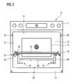
- FIG 2 shows a microwave cooking device 10 according to an embodiment of the present invention.
- the microwave cooking device 10 comprises a control panel 11, a rectangular cooking cavity 12 and a door 13, which is provided with a shielding and a wave trap.
- the cavity 12 comprises at its upper side 14 a magnetron for generating microwave radiation.
- At the rear wall 15 of the cavity 12 a fan is installed for circulating the air within the cavity 12.
- the cavity 12 is surrounded by a microwave shielding in a known manner.
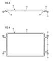
- the microwave cooking device 10 further comprises a rectangular tray 16, which extends essentially between the lateral side walls 17 of the cavity 12 and has the same horizontal dimensions.
- the tray 16 is made of glass and arranged on a support 18 composed of a flat frame 20.
- Each lateral side of the frame 20 is provided with a pair of protrusions 22 for holding cylindrical guiding rollers 24, which are in rolling contact with the opposite side walls 17 of the cavity 12.
- the rotational axes of the guiding rollers 24 are arranged horizontally so that the guiding rollers 24 are movable up- and downwards along the side walls 26.
- Two guiding elements 28 are arranged at the bottom of the support 18.
- Each guiding element 28 is provided in the form of a groove and extends in parallel to the lateral sides of the support 18. The opening of each groove 28 faces the bottom 29 of the cavity 12.
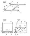
- a pivot lever 30 is arranged below the support 18, which pivot lever 30 is pivotably held by means of two pins 32.
- the pins 32 are positioned on a common lever pivot axis, which is indicated by the dashed line 34 in FIG 5 .
- a drive arm 36 and a tray arm 38 extend radially from each of the pins 32.
- the drive arm 36 is shorter than the tray arm 38 in order to create a lever transmission.
- the angle between the drive arm 36 and the tray arm 38 is approximately 120°.
- the tray arms 38 are connected by a bar element 40, which is orthogonally arranged there between.
- the free end of each tray arm 38 is provided with a roller element 42, which is movably received and guided in the groove 28 of the support 18.
- the pivot lever 30 is held at the rear end of the bottom 29 of the cavity 12.
- the free end of the drive arm 36 is connected to drive means 44 comprising a cylinder 46, which is fixed at the rear wall 15 of the cavity 12, and a piston 48, which acts on the free end
- the microwave cooking device 10 further comprises a sensor device for determining an upper limit for the vertical movement of the tray 16.
- the sensor device is connected to the driving system, which comprises a control device (not shown), which is adapted to control the driving means on the basis of the input from the sensor device.
- the sensor device comprises a light beam sensor, which is located in an upper region of the cavity 12 and comprises a light source 50, which is directed towards a light sink 52. An interruption of the light beam is detected by the light sink 52, whereupon the sensor device sends a control signal to the driving system.
- the operation of the microwave cooking device 10 is as follows.
- the tray 16 is located at the bottom of the cavity 12.
- An item to be heated usually some kind of foodstuff, is placed on top of the tray 16 and the door 13 is closed so that the cavity 12 is fully shielded.
- the magnetron is activated to generate microwave radiation.
- the driving system is activated to periodically perform a vertical upward and downward movement of the tray 16 inside the cavity 12.
- the driving system activates the driving means 44, which starts to push the piston 48 out of the cylinder 46.
- the linear movement of the driving means 44 which is indicted by arrow 60, is converted into a rotational movement of the pivot lever 30 around its lever pivot axis 34, which is indicated by arrow 62.
- the tray arm 38 starts rotating, it pushes the support 18 upwards along with the tray 16.
- the roller element 42 provided at the free end of the tray arm 38 is guided inside the groove 28 and rolls along the bottom of the support 18.
- the guiding rollers 24 roll along the side walls 17 of the cavity 12.
- the tray 16 When the tray 16 is further moved upwards, the item placed on the tray 16 interrupts the light beam emitted from the light source 50 towards the light sink 52. This interruption indicates that an upper limit for the vertical movement of the tray 16 is reached and the sensor device generates an input signal to the control device of the driving system. Upon reception of this signal, the driving system starts a reverse movement of its driving means, so that the tray 16 starts moving vertically downwards, until it reaches the bottom 29 of the cavity 12. Subsequently, the vertical upward and downward movement of the tray 16 is repeated until the item is sufficiently heated. If the heating process finishes at a time, when the tray 16 is arranged at an elevated position, the tray 16 is lowered automatically until it reaches the bottom 29 of the cavity 12, so that the heated item can be easily removed.
Landscapes
- Physics & Mathematics (AREA)
- Electromagnetism (AREA)
- Engineering & Computer Science (AREA)
- Power Engineering (AREA)
- Electric Ovens (AREA)
Priority Applications (1)
| Application Number | Priority Date | Filing Date | Title |
|---|---|---|---|
| EP09010427A EP2285182A1 (de) | 2009-08-13 | 2009-08-13 | Mikrowellenkochvorrichtung und -verfahren mit einem vertikal beweglichen Tablett |
Applications Claiming Priority (1)
| Application Number | Priority Date | Filing Date | Title |
|---|---|---|---|
| EP09010427A EP2285182A1 (de) | 2009-08-13 | 2009-08-13 | Mikrowellenkochvorrichtung und -verfahren mit einem vertikal beweglichen Tablett |
Publications (1)
| Publication Number | Publication Date |
|---|---|
| EP2285182A1 true EP2285182A1 (de) | 2011-02-16 |
Family
ID=41416262
Family Applications (1)
| Application Number | Title | Priority Date | Filing Date |
|---|---|---|---|
| EP09010427A Withdrawn EP2285182A1 (de) | 2009-08-13 | 2009-08-13 | Mikrowellenkochvorrichtung und -verfahren mit einem vertikal beweglichen Tablett |
Country Status (1)
| Country | Link |
|---|---|
| EP (1) | EP2285182A1 (de) |
Cited By (2)
| Publication number | Priority date | Publication date | Assignee | Title |
|---|---|---|---|---|
| US8814288B2 (en) | 2011-10-25 | 2014-08-26 | General Electric Company | Variable height slide-out rack for appliance |
| CN110547687A (zh) * | 2019-09-29 | 2019-12-10 | 宁波方太厨具有限公司 | 一种蒸制烹饪装置 |
Citations (7)
| Publication number | Priority date | Publication date | Assignee | Title |
|---|---|---|---|---|
| US3436506A (en) | 1965-04-08 | 1969-04-01 | Microtherm Ltd | Electronic heating apparatus |
| US4349713A (en) | 1980-02-19 | 1982-09-14 | Herman Marsen | Combined cooking and serving microwave apparatus |
| JPS60263028A (ja) | 1984-06-08 | 1985-12-26 | Matsushita Electric Ind Co Ltd | 加熱調理器 |
| EP0425198A2 (de) | 1989-10-25 | 1991-05-02 | Kabushiki Kaisha Toshiba | Kochgerät |
| US5667714A (en) | 1995-06-12 | 1997-09-16 | Samsung Electronics Co., Ltd. | Microwave oven having vertically reciprocable turn table |
| US5804800A (en) | 1995-08-31 | 1998-09-08 | Samsung Electronics Co., Ltd. | Turn table driving apparatus of microwave oven |
| US6028298A (en) | 1995-10-27 | 2000-02-22 | Samsung Electronics Co., Ltd. | Turntable driving apparatus of microwave oven and control method thereof |
-
2009
- 2009-08-13 EP EP09010427A patent/EP2285182A1/de not_active Withdrawn
Patent Citations (7)
| Publication number | Priority date | Publication date | Assignee | Title |
|---|---|---|---|---|
| US3436506A (en) | 1965-04-08 | 1969-04-01 | Microtherm Ltd | Electronic heating apparatus |
| US4349713A (en) | 1980-02-19 | 1982-09-14 | Herman Marsen | Combined cooking and serving microwave apparatus |
| JPS60263028A (ja) | 1984-06-08 | 1985-12-26 | Matsushita Electric Ind Co Ltd | 加熱調理器 |
| EP0425198A2 (de) | 1989-10-25 | 1991-05-02 | Kabushiki Kaisha Toshiba | Kochgerät |
| US5667714A (en) | 1995-06-12 | 1997-09-16 | Samsung Electronics Co., Ltd. | Microwave oven having vertically reciprocable turn table |
| US5804800A (en) | 1995-08-31 | 1998-09-08 | Samsung Electronics Co., Ltd. | Turn table driving apparatus of microwave oven |
| US6028298A (en) | 1995-10-27 | 2000-02-22 | Samsung Electronics Co., Ltd. | Turntable driving apparatus of microwave oven and control method thereof |
Cited By (3)
| Publication number | Priority date | Publication date | Assignee | Title |
|---|---|---|---|---|
| US8814288B2 (en) | 2011-10-25 | 2014-08-26 | General Electric Company | Variable height slide-out rack for appliance |
| CN110547687A (zh) * | 2019-09-29 | 2019-12-10 | 宁波方太厨具有限公司 | 一种蒸制烹饪装置 |
| CN110547687B (zh) * | 2019-09-29 | 2021-11-12 | 宁波方太厨具有限公司 | 一种蒸制烹饪装置 |
Similar Documents
| Publication | Publication Date | Title |
|---|---|---|
| CN113348728B (zh) | 家用烹饪器具和用于运行家用烹饪器具的方法 | |
| US8530797B2 (en) | Cooking appliance | |
| JP5850504B2 (ja) | 生地ベースの食品をベーキングするための装置、そのような製品をベーキングするためのネットおよび方法 | |
| EP0966180A2 (de) | Kochgerät | |
| KR102005480B1 (ko) | 컵라면 자동판매기의 전자렌지 조리장치 | |
| EP3672458A1 (de) | Grillgerät zum kochen auf bestellung und grillverfahren | |
| CN105165118A (zh) | 通过微波炉优先将电磁能量对准物体的偏冷区域进行加热 | |
| CN212186221U (zh) | 烤箱 | |
| CN109864607A (zh) | 烤箱 | |
| CN102444916A (zh) | 微波炉及其控制方法 | |
| CN113384162A (zh) | 烤箱 | |
| CN103392754A (zh) | 自动抓取摆盘机 | |
| CN104720618B (zh) | 电烤箱 | |
| CN108922053B (zh) | 自动煮面食售卖机 | |
| KR20140050475A (ko) | 전자레인지 | |
| JP2007029180A (ja) | 加熱調理装置 | |
| KR101155868B1 (ko) | 자동판매기의 가열 조리장치 | |
| KR102038288B1 (ko) | 음식물 자동판매기의 용기이송장치 | |
| KR20130036835A (ko) | 높이감지수단을 이용한 전동 장대높이뛰기 지주 | |
| KR102954813B1 (ko) | 조리기기 | |
| JP2003287232A (ja) | 加熱調理器 | |
| KR101520093B1 (ko) | 조리기기 | |
| JP2021081141A (ja) | 加熱機器 | |
| WO2017049622A1 (zh) | 微波加热装置 | |
| CN223608383U (zh) | 一种烤箱自动开关门机构 |
Legal Events
| Date | Code | Title | Description |
|---|---|---|---|
| PUAI | Public reference made under article 153(3) epc to a published international application that has entered the european phase |
Free format text: ORIGINAL CODE: 0009012 |
|
| 17P | Request for examination filed |
Effective date: 20100208 |
|
| AK | Designated contracting states |
Kind code of ref document: A1 Designated state(s): AT BE BG CH CY CZ DE DK EE ES FI FR GB GR HR HU IE IS IT LI LT LU LV MC MK MT NL NO PL PT RO SE SI SK SM TR |
|
| AX | Request for extension of the european patent |
Extension state: AL BA RS |
|
| RAP1 | Party data changed (applicant data changed or rights of an application transferred) |
Owner name: ELECTROLUX HOME PRODUCTS CORPORATION N.V. |
|
| RAP1 | Party data changed (applicant data changed or rights of an application transferred) |
Owner name: ELECTROLUX HOME PRODUCTS CORPORATION N.V. |
|
| STAA | Information on the status of an ep patent application or granted ep patent |
Free format text: STATUS: THE APPLICATION IS DEEMED TO BE WITHDRAWN |
|
| 18D | Application deemed to be withdrawn |
Effective date: 20150303 |