EP2286041B1 - Systeme de toit pour batiment - Google Patents
Systeme de toit pour batiment Download PDFInfo
- Publication number
- EP2286041B1 EP2286041B1 EP09710726.2A EP09710726A EP2286041B1 EP 2286041 B1 EP2286041 B1 EP 2286041B1 EP 09710726 A EP09710726 A EP 09710726A EP 2286041 B1 EP2286041 B1 EP 2286041B1
- Authority
- EP
- European Patent Office
- Prior art keywords
- roof
- panels
- trusses
- formation
- roof system
- Prior art date
- Legal status (The legal status is an assumption and is not a legal conclusion. Google has not performed a legal analysis and makes no representation as to the accuracy of the status listed.)
- Not-in-force
Links
- 239000000463 material Substances 0.000 claims description 35
- 230000015572 biosynthetic process Effects 0.000 claims description 26
- 238000005755 formation reaction Methods 0.000 claims description 26
- 239000004033 plastic Substances 0.000 claims description 26
- 229920003023 plastic Polymers 0.000 claims description 26
- 230000000007 visual effect Effects 0.000 claims description 6
- 238000007789 sealing Methods 0.000 claims description 5
- 230000000717 retained effect Effects 0.000 claims description 3
- 239000012530 fluid Substances 0.000 claims description 2
- PUMRUSBKNSBTAL-UHFFFAOYSA-N 3,4-dihydro-2h-chromene-2-carbaldehyde Chemical compound C1=CC=C2OC(C=O)CCC2=C1 PUMRUSBKNSBTAL-UHFFFAOYSA-N 0.000 claims 1
- 239000011810 insulating material Substances 0.000 description 7
- 238000004519 manufacturing process Methods 0.000 description 5
- 238000010276 construction Methods 0.000 description 4
- 238000009413 insulation Methods 0.000 description 4
- 239000002131 composite material Substances 0.000 description 3
- 239000012774 insulation material Substances 0.000 description 3
- XLYOFNOQVPJJNP-UHFFFAOYSA-N water Substances O XLYOFNOQVPJJNP-UHFFFAOYSA-N 0.000 description 3
- 239000002023 wood Substances 0.000 description 3
- 238000009414 blockwork Methods 0.000 description 1
- 238000009435 building construction Methods 0.000 description 1
- 239000004927 clay Substances 0.000 description 1
- 238000005520 cutting process Methods 0.000 description 1
- 230000001934 delay Effects 0.000 description 1
- 230000000694 effects Effects 0.000 description 1
- 230000007613 environmental effect Effects 0.000 description 1
- 238000001125 extrusion Methods 0.000 description 1
- 239000000835 fiber Substances 0.000 description 1
- 239000006260 foam Substances 0.000 description 1
- -1 for example Substances 0.000 description 1
- 238000009434 installation Methods 0.000 description 1
- 238000005304 joining Methods 0.000 description 1
- 239000002184 metal Substances 0.000 description 1
- 238000000034 method Methods 0.000 description 1
- 239000000203 mixture Substances 0.000 description 1
- 238000012856 packing Methods 0.000 description 1
- 239000002994 raw material Substances 0.000 description 1
- 239000010454 slate Substances 0.000 description 1
- 238000009751 slip forming Methods 0.000 description 1
- 239000007787 solid Substances 0.000 description 1
- 239000004575 stone Substances 0.000 description 1
Images


Classifications
-
- E—FIXED CONSTRUCTIONS
- E04—BUILDING
- E04B—GENERAL BUILDING CONSTRUCTIONS; WALLS, e.g. PARTITIONS; ROOFS; FLOORS; CEILINGS; INSULATION OR OTHER PROTECTION OF BUILDINGS
- E04B7/00—Roofs; Roof construction with regard to insulation
- E04B7/02—Roofs; Roof construction with regard to insulation with plane sloping surfaces, e.g. saddle roofs
- E04B7/022—Roofs; Roof construction with regard to insulation with plane sloping surfaces, e.g. saddle roofs consisting of a plurality of parallel similar trusses or portal frames
-
- E—FIXED CONSTRUCTIONS
- E04—BUILDING
- E04B—GENERAL BUILDING CONSTRUCTIONS; WALLS, e.g. PARTITIONS; ROOFS; FLOORS; CEILINGS; INSULATION OR OTHER PROTECTION OF BUILDINGS
- E04B7/00—Roofs; Roof construction with regard to insulation
- E04B7/20—Roofs consisting of self-supporting slabs, e.g. able to be loaded
- E04B7/22—Roofs consisting of self-supporting slabs, e.g. able to be loaded the slabs having insulating properties, e.g. laminated with layers of insulating material
-
- E—FIXED CONSTRUCTIONS
- E04—BUILDING
- E04D—ROOF COVERINGS; SKY-LIGHTS; GUTTERS; ROOF-WORKING TOOLS
- E04D3/00—Roof covering by making use of flat or curved slabs or stiff sheets
- E04D3/35—Roofing slabs or stiff sheets comprising two or more layers, e.g. for insulation
- E04D3/351—Roofing slabs or stiff sheets comprising two or more layers, e.g. for insulation at least one of the layers being composed of insulating material, e.g. fibre or foam material
Definitions
- the invention to which this application relates is an improved roof system for a building, such as, but not exclusively, a roof of a domestic premises.
- roof systems There are many different types of roof systems currently used and the type of system to which this invention is directed, is that which comprises a series of trusses which are joined together to form a double or single pitched roof.
- the external roof surface is then defined by a series of tiles which are interlocked to form a roof which allows the drainage of rainwater therefrom into gutters.
- roof trusses which are made from wood
- wall panels which can be made from wood or other fibre sheet material such as MDF
- tiles which can be manufactured from stone, such as slate, or composite materials such as, for example, clay and, in which case, the composite material is formed into a particular shape to aid interlocking and/or drainage.
- wooden trusses are provided to run along a vertical axis from the top of the pitched roof to the bottom of the same and the wooden battens are provided to run along a horizontal axis spanning across the trusses.
- the tiles are provided with support means or engagement means which pass through the same so that each tile is provided to be located on at least one batten.
- the tiles are of a width such that a number of the same are required to be placed side by side along the horizontal axis to span the distance between the trusses. It will therefore be appreciated that a large number of tiles are required to form the roof and that each of the tiles is required to be individually fitted in position.
- a further problem with the conventional roofing systems is that the same are constructed from components which are typically required to be sourced and supplied from a number of different organisations and locations. This can lead to incorrect ordering, time delays and general frustration during the construction process.
- a further problem which exists with conventional roof systems is that they are heavy and therefore represent a significant part of the overall weight of the building. This is in turn means that the foundations required to support the building are required to be of significant depth which increases the cost of the building in terms of materials used and labour costs.
- a yet further problem is the increasing requirement to be able to provide increased insulation materials in buildings in an efficient manner so as improve the efficiency of the building.
- WO92/02696 discloses a roofing system according to the preamble of claim 1 wherein the multiple components of the roof are constructed from plastics material.
- An aim of the present invention is therefore to provide components for a roof system which are manufactured and provided in a particular form so as to provide efficiency, consistency of manufacture and also to be of economic benefit and reduce the number of different components required to form the roof.
- a further aim of the invention is to provide a roof system which utilises components which, in conjunction, provide a system which is consistent in terms of quality and can have an increased life span and overcome or reduce the problems indicated above.
- a further aim is to provide a system which allows the ability for the components of the system to be provided from a reduced number, or single, supplier and location.
- the panels are provided so as to span two or more gaps between trusses.
- the panels are formed such that a portion adjacent each vertical edge of the panels overlies at least part of a truss.
- the panels have vertical and horizontal interfaces with adjacent panels, and the horizontal interface one of the panels is provided with a lip portion which overlies the adjacent panel.
- the support members are provided at the interfaces to underlie the same.
- the panels include a layer of insulating material, said material preferably formed integrally with the panels under factory conditions.
- the insulation material is attached to the tile.
- the layer of insulation material is formed on the inner facing surface of the tile.
- further layers of insulating material can be provided within the roof system and lying between the inner surface of the tile and the ceiling of the room below.
- the panels are provided with preformed engagement means formed in the edge wall thereof such that a first wall has a first formation located thereon, a second opposing wall has a second formation located thereon and when said first and second edges of first and second panels are brought together engagement of the panels together can be achieved.
- the engagement is achieved by a relative pivotal movement between the panels edges.
- the engagement means are located on the truss via a first arm, said arm connected to second and third arms which oppose each other and which arms engage, respectively, with the edges of panels brought into an abutting relationship therewith.
- the engagement means are provided with a rebated section which can act as a channel along which fluid can flow to be drained.
- a rebated section which can act as a channel along which fluid can flow to be drained.
- matching rebates are provided in adjacent panel edges with the rebates provided of a form so as to have sufficient tolerance to allow efficient and accurate site installation.
- the cover means can be moved into and retained in position with respect to the panels by a snap fit action.
- the tiles are located directly on the roof trusses thereby meaning that the conventional use of battens between the trusses is not required, and thereby reducing the number of different components and amount of materials which are required to be used.
- the plastics material which is used is PVC although it is envisaged that other plastic materials or composite mixtures can be used. In certain embodiments, different plastic materials may be used to form different components.
- the roof trusses which are used are formed to a required length or alternatively, may be continuously formed and then subsequently cut to a required length to suit particular roof system designs.
- the roof trusses are manufactured by extrusion moulding and may be delivered on site in uniform lengths for subsequent cutting to the required length. Alternatively, the same can be cut to the required length at the location of manufacture and then transported for the formation of a particular roof system.
- location means may be formed in the components at the time of manufacture or may be formed subsequently at the location of construction of the roof system.
- roof panels in the roof system are provided of the same design and said design includes a female engagement means and a male engagement formation, typically formed at opposing edges of said roof panel.
- the female engagement formation is provided to receive a male engagement formation of an adjacent roof panel, when positioned on the roof, to thereby allow adjacent roof panels to be interlocked.
- At least one location formation on the inner face of the panel, there is provided at least one location formation, said formation formed to allow the same to engage with one of the trusses and thereby support the panel in position on the truss.
- the location formation is an elongate groove.
- the boards used to form the ceiling are attached to the underside of the trusses.
- the roof panels can be provided with, along certain edges, sealing formations or alternatively, when fitted in position on the roof system, sealing means are located between the adjacent panels.
- the sealing means comprise a plurality of strips which are spaced apart across the depth of the roof panel to thereby prevent the ingress of water between the roof panels.
- the roof system includes wall plates, which depend downwardly from the location of the ends of the roof trusses and the top face of the wall which support the roof system.
- these wall plates are also made of plastics material.
- the trusses are respectively joined together to form the roof frame using gusset plates, which are manufactured from plastics.
- noggins are provided between rafter members of the roof which are manufactured from plastics material and any packing members can also, if required, be manufactured from plastics material.
- ridge tiles can be located, said ridge tiles can also be formed of plastics material.
- a roof system which is wholly formed of components formed of plastics material, with the plastics material being formed into the required components, with significantly tighter tolerances than the conventional materials used to form said components.
- the invention is particularly of use with regard to a roof system according which is pitched or sloped.
- a roof system including a series of trusses, interconnected to form a roof frame, and a plurality of roof panels or tiles, supported by said roof trusses, and wherein any one or combination of the roof trusses and/or roof panels or tiles, are manufactured from a plastics material.
- a roof panel or tile said roof panel or tile manufactured from plastics material and having at one edge, a male location member formed therein and, at the opposing edge, a female engagement means formed therein, said male and female engagement means provided to interlock with respective male and female engagement means on adjacent roof panels or tiles when placed together in appropriate orientation as part of a roof and characterised in that the panel or tile includes a layer of insulating material.
- the external face of the roof panel is provided with one or more markings to give the visual appearance that the panel is formed of a plurality of smaller conventional tiles.
- At least the surface of the panel which faces inwardly when fitted includes or is formed by a layer of insulating material.
- a roof system comprising trusses and roof tiles, and wherein the trusses are formed of plastics material.
- FIG. 1 there is illustrated a view of part of a sloped roof 2 which has an external face 4 formed from a plurality of panels 6, 8.
- the panels are supported on a series of spaced apart trusses 10, shown in broken lines and which run from the ridge 12 of the roof down to the lower edge.
- the panels are provided with horizontal interfaces 16 with adjacent panels and one of these is shown in more detail in Figure 2 .
- the interface between the respective edges 18, 20 of panels 6,8 is provided with a lip portion 22 which is formed on the edge 18 of the upper panel and hence masks the interface from moisture.
- a lower support member 24 is also shown which can be provided to lie in a substantially horizontal plane and these support members can be positioned to underlie the interface.
- the underside of the panels can be formed with a layer of insulating material 26.
- the topside 28 of the panels can be made from plastics material.
- the panels can be made of a width to suit specific requirements and typically will be of a width so as to span the gap 30 between adjacent trusses as shown in Figure 1 . However the panels may be made wider such that they also span the gap 32 or gap 34 between four trusses as shown. In one embodiment the lengths of the panels 36 can be in metres such as 6-8 metres lengths. However, in whichever embodiment, the interfaces between adjacent panels are formed so as to allow expansion due to environmental conditions to be taken into account.
- FIG. 3-5 the interface between the panel edges which lie in the vertical plane are shown.
- the panels are formed and located such that the interface 38 lies on a truss 10 as shown in each case and as a result a portion of the panels on each side of the interface 38 overlie and are supported by a truss.
- the panels shown are panel 6 from Figure 1 and a panel 40 to the right hand side of the same as looking at Figure 1 .
- the engagement means have a first arm 44 received by the truss 10, and second and third arms 46, 48 which are received by the edges of the panels 6 and 40 respectively in a dovetail slot arrangement formed in each of the panels edges and the truss.
- the first arm and indeed the engagement means may be provided as an integral part of the truss such that the edges of the panels can be slid along the same to form the interface 38.
- the engagement means can be formed as an integral part of the edge of one of the panels.
- the engagement means providing mechanical engagement between the panels, it also provides a secondary seal at the interface.
- Figure 4 illustrates a further arrangement in which in this case the engagement means at the interface is formed by two arms 50, 52 which are received in the respective edges of the panels 6, 40 in slots formed therein. Additional engagement with the truss 10 can be achieved using screws 54 and/or hook portions 56 so as to secure the panels to the truss.
- FIG. 5 there is illustrated a further engagement means arrangement in which the adjacent edges of the panels can be joined together without the provision of separate engagement means but by using formations 60, 62 integrally provided on the panels edges themselves. In this case a pivoting action between the panels allows the locking engagement of the panels.
- Additional securing means 64 can be used to secure one of the panels to the truss 10.
- one of the panels 40 is provided with a n overlapping formation 66 which acts as a cover for the interface 38.
- a cover means 68 is provided which has clip features 70 to be received in formations 72 on the edges of panels 6, 40 so as to allow the cover to be retained in position and hence protect the interface 38 from the ingress of water.
- the top face can be formed so as to act as a secondary drainage channel 74 along which water can be drained.
- the hook formation 62 can be used as a drainage channel.
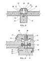
- FIG. 6 illustrates an assembly of the ridge 104 of the roof system 102 in cross section and shows the ridge tiles 106 which pass along the ridge 104, and depending downwardly therefrom on either side, roof panels 108.
- the roof panels are supported on a roof frame formed of a series of truss members 110 and, if required, additional longitudinal ties 112 can be provided to add to the stability of the roof system.
- each of the components of the roof, ridge tiles 106, roof panels 108 and trusses 110 are formed from plastics, typically PVC, material and therefore there is no wood or other materials used in the roof system.
- the ridge tile is secured in place on the roof panels 108 by using a pre-formed fixing 114 formed in the roof panels 108 which are to be used for the ridge and a rubber seal can be provided at that location so as to provide the seal between the ridge tile and the roof tile.
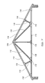
- Figure 7 illustrates the frame of the roof system 102 in more detail, with the tiles removed, thereby showing the roof frame manufactured by the joining together of a series of the plastic truss members 110.
- the truss members can be provided as a series of uniform lengths, which are then cut to a suitable length at the location of manufacture of the roof frame.
- the truss members can be formed to the required length, at the factory to suit a particular order.
- the respective ends of the trusses 110 are joined to other trusses using plates 116 which, in this case, are of metal.
- FIG 8 illustrates a more detailed view of the eaves of the roof system 102 and shows the roof panels 108 depending downwardly such that the free edge 118 of the same leads into the gutter, facia and soffit assembly 120 which can also be manufactured of plastics material.
- the roof system is supported on the walls of the building, one of which 122 is shown and which comprises a cavity wall arrangement 124 and inner wall plate 126 which can be manufactured from plastics material such as PVC and which acts to support, at the top end 128, the roof frame formed by the trusses 110.
- the wall plate 126 is strapped to the inner block work 136 by a series of straps 130 as shown.
- Figures 9 and 10 illustrate an alternative roof system for a mono-pitched roof 132
- Figure 9 illustrates the roof frame formed by a series of the truss members 110 and plates 116 which join the same together.
- a wall plate 126 is provided at one edge and again the wall plates and trusses are formed of PVC material.
- the roof panels 108 are supported on the trusses 110 of plastics material and, at the interface between the roof panels and the wall 134, there is provided flashing 138 to provide a watertight seal between the top of the roof panel 108 and the inner face of the wall 134.
- the end 140 of the truss member 110 can be built into the cavity wall 134 as illustrated to provide additional support and this is repeated with the end 142 of the truss member 110 at the top of the roof.
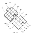
- FIG. 11 there are illustrated two roof panels 108, in accordance with the invention, each manufactured from plastics material and which can be provided, as required, with an inner facing surface formed of insulating material to thereby provide an insulating effect.
- Each tile is provided with a male engagement formation 146 on edge 144 and a female engagement formation 148 on edge 150. These respective engagement formations, are provided to interlock as indicated by the arrow 152 when the panels are placed in position on the roof with the edges 144 and 150 being positioned parallel with the direction of slope 154 of the roof.
- the panels can also be provided with a location groove 149 which runs along the width of the panel and allows the tile to be located on an underlying truss.
- a further important feature of the invention with regard to the roof panels is that the same can be provided with lines of detail 156 on the external face which allow the external face of the panel to have a visual appearance of a series of smaller tiles, in this case 16 tiles, to give the visual appearance of 16 tiles being used to cover the area which is in fact covered by only one panel 108 thereby providing the finished roof with a more traditional visual appearance.
- roof panels can be added to the roof panels to provide a particular finish and/or to improve the life of the same.
- the system of the invention allows the removal of excessive skills and steps which are conventionally required to form a roof structure. This is achieved by the development of a system which allows integrated insulation to be provided, which removes the need for sarking felt and battens to be used.
- the system can be used with kits manufactured under factory conditions which reduces time of construction on site and allows the components to be manufactured in controlled environments.
- the system can also be adapted to provide additional usable space within the roof and for built in roof lights to be provided as an option.
- the panels can be moulded from plastics material , foam or the like and may be made as a solid item or with channels and/or pockets in which insulating material can be located.
- the present invention therefore provides a roof system which can be utilised to significant benefit both in the construction of the same and with regard to the finished roof.
- a roofing system which facilitates the interconnection of adjacent panels directly and also onto the underlying truss at the interface between panel edges which removes the need for cross purlins or beams which would conventionally be used for attachment of large industrial panels and battens which would be used for attachment of slates or tiles.
- a roof system and components therefore, which are manufactured from plastics material rather than conventional materials and which as shown in the accompanying figures, can be utilised together, in conjunction, to form a roof system which can efficiently be manufactured and constructed. Furthermore a reduced number of components and materials may be used such as the fact that battens are not required to be used and the roof system can have improved insulation by providing the tiles with insulating characteristics. This is in addition to the fact that due to the structure and components and materials used, the overall weight of the roof system in accordance with the invention is significantly lighter than conventional roofs for the same building.
- the overall building is lighter and hence the foundations which are required for the building can be reduced in size and/or depth in comparison to those required for the equivalent conventional building. It will therefore be appreciated that the direct benefits with respect to the roof also provide further benefits in the overall building construction. Furthermore in many cases the visual appearance and life of the roof system which is created is also improved.
Landscapes
- Engineering & Computer Science (AREA)
- Architecture (AREA)
- Civil Engineering (AREA)
- Structural Engineering (AREA)
- Physics & Mathematics (AREA)
- Electromagnetism (AREA)
- Building Environments (AREA)
- Roof Covering Using Slabs Or Stiff Sheets (AREA)
Claims (16)
- Système de toiture entièrement formé de composants constitués de matières en plastique, ledit système comprenant une pluralité de fermes (10), chacune des fermes étant posée le long d'un axe respectif sensiblement vertical, et lesdites fermes étant espacées les unes des autres le long de la largeur du toit destiné à être formé et étant revêtues par une pluralité de panneaux en plastique (6, 8) afin de constituer la face externe (4) du toit, et lesdits panneaux ayant une certaine largeur de sorte à franchir l'espace (32, 34) entre au moins deux fermes adjacentes, alors que les interfaces sensiblement verticales (38) entre des panneaux respectifs (6, 8) sont positionnées pour couvrir une ferme (10), et prévues pour permettre un certain degré d'expansion thermique des panneaux devant être mis en place, caractérisé en ce que les panneaux sont agencés de sorte qu'ils n'aboutent pas au niveau des interfaces verticales et que le système inclut, au-dessus desdites interfaces verticales (38) des panneaux, des moyens de recouvrement (68) pour empêcher toute pénétration d'humidité, cas dans lequel lesdits moyens de recouvrement sont retenus en position par des dispositifs à clip (70) reçus dans des formations (72) formées dans les bords des panneaux (6, 8), et en ce qu'il comporte en outre des moyens d'emboîtement (42) qui sont positionnés de façon à emboîter les panneaux adjacents (6, 8) les uns aux autres au niveau de l'interface (38) et/ou lesdits panneaux avec la ferme sous-jacente (10) ou l'élément de support.
- Système selon la revendication 1, les panneaux (6, 8) étant formés de sorte qu'une portion adjacente à chaque bord vertical des panneaux (6, 8) couvre au moins une partie d'une ferme (10).
- Système selon la revendication 1, des panneaux adjacents (6, 8) possédant des interfaces verticales et horizontales, l'interface horizontale des panneaux (6, 8) étant munie d'une portion lèvre (22) qui couvre le panneau adjacent.
- Système selon la revendication 1, les panneaux (6, 8) étant munis de moyens d'emboîtement préformés formés dans la paroi de bord de ceux-ci, de sorte qu'une première paroi possède une première formation qui est positionnée dans celle-ci et qu'une deuxième paroi opposée possède une deuxième formation qui est positionnée dans celle-ci.
- Système selon la revendication 1, les moyens d'emboîtement (42) étant positionnés sur la ferme (10) par l'intermédiaire d'un premier bras, ledit bras étant raccordé à un deuxième et à un troisième bras, qui sont opposés l'un à l'autre, et ces bras s'emboîtent respectivement avec les bords de panneaux (6, 8) amenés en relation d'aboutement avec ceux-ci.
- Système selon la revendication 4, les moyens d'emboîtement étant munis d'une section feuillurée laquelle peut servir de section en U le long de laquelle du fluide peut s'écouler pour être évacué.
- Système de toiture selon la revendication 1, les panneaux de toit (6, 8) étant munis d'au moins un moyen d'emboîtement femelle (148) et d'au moins une formation d'emboîtement mâle (146).
- Système de toiture selon la revendication 7, la formation d'emboîtement mâle (146) et le moyen d'emboîtement femelle (148) étant formés au niveau d'extrémités sensiblement opposées du panneau de toit (6, 8).
- Système de toiture selon la revendication 1, dans lequel est prévue au moins une formation de positionnement (149) pour permettre à un panneau (6, 8) de s'emboîter avec une ou plusieurs fermes.
- Système de toiture selon la revendication 9, la formation de positionnement (149) étant une fente allongée.
- Système de toiture selon la revendication 1, au moins un bord du panneau de toit (6, 8) possédant une formation d'étanchéisation (162).
- Système de toiture selon la revendication 11, la formation d'étanchéisation (162) comprenant une pluralité de bandes situées à une certaine distance d'espacement en travers de la profondeur du panneau de toit (6, 8).
- Système de toiture selon la revendication 1, le système incluant au moins une plaque murale (116).
- Système de toiture selon la revendication 13, les plaques murales (116) étant sensiblement positionnées entre les extrémités des fermes de toit (10) et la face supérieure du mur.
- Système de toiture selon la revendication 1, les fermes (10) étant jointes les unes aux autres grâce à l'utilisation d'au moins un gousset fabriqué en matière plastique.
- Système de toiture selon la revendication 1, la face externe du panneau de toit (6, 8) étant munie d'un ou de plusieurs marquages qui donnent l'apparence visuelle que la tuile est constituée d'une pluralité de tuiles plus petites.
Applications Claiming Priority (3)
| Application Number | Priority Date | Filing Date | Title |
|---|---|---|---|
| GB0802509A GB0802509D0 (en) | 2008-02-12 | 2008-02-12 | Building roof system |
| GB0812323A GB0812323D0 (en) | 2008-07-05 | 2008-07-05 | Roof system |
| PCT/GB2009/000390 WO2009101408A1 (fr) | 2008-02-12 | 2009-02-12 | Système de toit pour bâtiment |
Publications (2)
| Publication Number | Publication Date |
|---|---|
| EP2286041A1 EP2286041A1 (fr) | 2011-02-23 |
| EP2286041B1 true EP2286041B1 (fr) | 2014-06-18 |
Family
ID=40535527
Family Applications (1)
| Application Number | Title | Priority Date | Filing Date |
|---|---|---|---|
| EP09710726.2A Not-in-force EP2286041B1 (fr) | 2008-02-12 | 2009-02-12 | Systeme de toit pour batiment |
Country Status (4)
| Country | Link |
|---|---|
| US (1) | US8898962B2 (fr) |
| EP (1) | EP2286041B1 (fr) |
| AU (1) | AU2009213882B2 (fr) |
| WO (1) | WO2009101408A1 (fr) |
Families Citing this family (4)
| Publication number | Priority date | Publication date | Assignee | Title |
|---|---|---|---|---|
| US8474207B1 (en) * | 2012-06-12 | 2013-07-02 | John A Gilbert | Strengthening wood frame construction against wind damage |
| JP6227936B2 (ja) * | 2013-08-23 | 2017-11-08 | 株式会社日本ピット | 屋外用パネル |
| JP7146485B2 (ja) * | 2018-06-28 | 2022-10-04 | 元旦ビューティ工業株式会社 | 建築物の軒先下地構造 |
| USD1120383S1 (en) * | 2024-01-10 | 2026-03-24 | Kyle Tompane | Truss construction module |
Citations (3)
| Publication number | Priority date | Publication date | Assignee | Title |
|---|---|---|---|---|
| NL8103038A (nl) * | 1981-06-23 | 1983-01-17 | Multinorm Bv | Bouwconstructie, bouwpanelen, hulp- en passtukken daarvoor, alsmede werkwijze voor het vervaardigen van de panelen. |
| JPH10140752A (ja) * | 1996-11-14 | 1998-05-26 | Daido Steel Sheet Corp | 屋根材の接続構造 |
| US20040163328A1 (en) * | 2003-02-25 | 2004-08-26 | Riley John Michael | Insulated glazed roofing system |
Family Cites Families (14)
| Publication number | Priority date | Publication date | Assignee | Title |
|---|---|---|---|---|
| US2181074A (en) * | 1939-05-27 | 1939-11-21 | Alfol Insulation Company Inc | Heat insulating panel |
| US3807100A (en) * | 1971-08-16 | 1974-04-30 | Prod Specialties Inc | Building construction with elongated support member and interfitting panels |
| SE415046B (sv) * | 1978-09-07 | 1980-09-01 | Settergren Ab Claes | Tetnings- och isoleringsanordning vid fogar mellan byggnadselement |
| FR2506813A1 (fr) * | 1981-06-02 | 1982-12-03 | Bouygues Sa | Element de toiture |
| US4463533A (en) * | 1982-06-24 | 1984-08-07 | Mullet Willis J | Sheet material roofing panel |
| GB2123050B (en) * | 1982-06-25 | 1986-01-29 | Marley Roof Tile | Roof ridge capping system |
| DE3626760A1 (de) * | 1986-08-07 | 1988-02-11 | Bert Engelhorn | Tragkonstruktion fuer kunststoff-eingedeckte hallen, insbesondere gewaechshaeuser, und profile als bestandteile derselben |
| GB9017244D0 (en) * | 1990-08-07 | 1990-09-19 | Knight Andrew | Flat pack pitched roofing system |
| SE508578C2 (sv) * | 1997-02-20 | 1998-10-19 | Sten Engwall | Takmodul, byggnadstak samt förfaranden vid tillverkning respektive uppförande av sådana |
| US20010020353A1 (en) * | 1999-02-24 | 2001-09-13 | Carr Michael J. | Modular truss |
| GB0013608D0 (en) * | 2000-06-06 | 2000-07-26 | Cain David | Fac-simile thatch/straw/reed/tile roof covering system |
| US7441379B2 (en) * | 2003-06-27 | 2008-10-28 | Konvin Associates Limited Partnership | Light transmission panels, retaining clip and a combination thereof |
| US7658038B2 (en) * | 2004-03-29 | 2010-02-09 | Lifetime Products, Inc. | System and method for constructing a modular enclosure |
| US20070261340A1 (en) * | 2006-05-02 | 2007-11-15 | Huber Engineered Woods Llc | Method and system for installation of diverse exterior sheathing components of buildings |
-
2009
- 2009-02-12 WO PCT/GB2009/000390 patent/WO2009101408A1/fr not_active Ceased
- 2009-02-12 AU AU2009213882A patent/AU2009213882B2/en not_active Ceased
- 2009-02-12 EP EP09710726.2A patent/EP2286041B1/fr not_active Not-in-force
-
2010
- 2010-08-12 US US12/855,278 patent/US8898962B2/en not_active Expired - Fee Related
Patent Citations (3)
| Publication number | Priority date | Publication date | Assignee | Title |
|---|---|---|---|---|
| NL8103038A (nl) * | 1981-06-23 | 1983-01-17 | Multinorm Bv | Bouwconstructie, bouwpanelen, hulp- en passtukken daarvoor, alsmede werkwijze voor het vervaardigen van de panelen. |
| JPH10140752A (ja) * | 1996-11-14 | 1998-05-26 | Daido Steel Sheet Corp | 屋根材の接続構造 |
| US20040163328A1 (en) * | 2003-02-25 | 2004-08-26 | Riley John Michael | Insulated glazed roofing system |
Also Published As
| Publication number | Publication date |
|---|---|
| WO2009101408A1 (fr) | 2009-08-20 |
| EP2286041A1 (fr) | 2011-02-23 |
| AU2009213882B2 (en) | 2014-08-21 |
| US8898962B2 (en) | 2014-12-02 |
| US20110197527A1 (en) | 2011-08-18 |
| AU2009213882A1 (en) | 2009-08-20 |
Similar Documents
| Publication | Publication Date | Title |
|---|---|---|
| US12173507B2 (en) | Roofing panels with water shedding features | |
| US4065899A (en) | Interlocking combination shingle and sheeting arrangement | |
| US20140099877A1 (en) | Roof deck intake vent | |
| GB2062056A (en) | Roofing laths and roofs incorporating such laths | |
| US20080053004A1 (en) | Roof assembly | |
| US11639604B1 (en) | Triangular standing seam metal roof panel and cover system | |
| EP2286041B1 (fr) | Systeme de toit pour batiment | |
| US6952901B2 (en) | Panel mounted shingles assembly with ventilating screen | |
| US20110154743A1 (en) | Unitary Fascia And Gutter | |
| US7673423B2 (en) | Cladding apparatus, method and system | |
| EP0953693A1 (fr) | Système universel pour l'isolation de toitures et/ou de murs | |
| JP7187232B2 (ja) | 軒天見切の防水構造 | |
| GB2523738A (en) | Combined roof insulation and tile support panel system | |
| EP0814216A1 (fr) | Structure composite préfabriquée pour toit en pente | |
| JP7481853B2 (ja) | 屋根構造 | |
| EP0401438B1 (fr) | Recouvrement de toits | |
| JP6963985B2 (ja) | 外壁見切り部の防水構造とその形成方法 | |
| JP6889528B2 (ja) | 屋根構造及び屋根材 | |
| GB2323865A (en) | Insulating roof tile | |
| GB2318595A (en) | Roofing slab for supporting cladding, e.g.tiles | |
| GB2613936A (en) | A roof waterproofing element | |
| JPH11303327A (ja) | 傾斜屋根用屋根材及び屋根構造 | |
| GB2413806A (en) | Adjoining roof coverings using roof gutter units or strips thereof | |
| Blanc | 28 Decking and built up roofing | |
| Seeley | Roofs |
Legal Events
| Date | Code | Title | Description |
|---|---|---|---|
| PUAI | Public reference made under article 153(3) epc to a published international application that has entered the european phase |
Free format text: ORIGINAL CODE: 0009012 |
|
| 17P | Request for examination filed |
Effective date: 20101119 |
|
| AK | Designated contracting states |
Kind code of ref document: A1 Designated state(s): AT BE BG CH CY CZ DE DK EE ES FI FR GB GR HR HU IE IS IT LI LT LU LV MC MK MT NL NO PL PT RO SE SI SK TR |
|
| AX | Request for extension of the european patent |
Extension state: AL BA RS |
|
| RAP1 | Party data changed (applicant data changed or rights of an application transferred) |
Owner name: INGHAM, MARTIN |
|
| RIN1 | Information on inventor provided before grant (corrected) |
Inventor name: INGHAM, MARTIN |
|
| DAX | Request for extension of the european patent (deleted) | ||
| 17Q | First examination report despatched |
Effective date: 20110502 |
|
| GRAP | Despatch of communication of intention to grant a patent |
Free format text: ORIGINAL CODE: EPIDOSNIGR1 |
|
| INTG | Intention to grant announced |
Effective date: 20131028 |
|
| GRAS | Grant fee paid |
Free format text: ORIGINAL CODE: EPIDOSNIGR3 |
|
| GRAA | (expected) grant |
Free format text: ORIGINAL CODE: 0009210 |
|
| AK | Designated contracting states |
Kind code of ref document: B1 Designated state(s): AT BE BG CH CY CZ DE DK EE ES FI FR GB GR HR HU IE IS IT LI LT LU LV MC MK MT NL NO PL PT RO SE SI SK TR |
|
| REG | Reference to a national code |
Ref country code: GB Ref legal event code: FG4D |
|
| REG | Reference to a national code |
Ref country code: CH Ref legal event code: EP |
|
| REG | Reference to a national code |
Ref country code: AT Ref legal event code: REF Ref document number: 673460 Country of ref document: AT Kind code of ref document: T Effective date: 20140715 |
|
| REG | Reference to a national code |
Ref country code: IE Ref legal event code: FG4D |
|
| REG | Reference to a national code |
Ref country code: DE Ref legal event code: R096 Ref document number: 602009024739 Country of ref document: DE Effective date: 20140731 |
|
| PG25 | Lapsed in a contracting state [announced via postgrant information from national office to epo] |
Ref country code: LT Free format text: LAPSE BECAUSE OF FAILURE TO SUBMIT A TRANSLATION OF THE DESCRIPTION OR TO PAY THE FEE WITHIN THE PRESCRIBED TIME-LIMIT Effective date: 20140618 Ref country code: FI Free format text: LAPSE BECAUSE OF FAILURE TO SUBMIT A TRANSLATION OF THE DESCRIPTION OR TO PAY THE FEE WITHIN THE PRESCRIBED TIME-LIMIT Effective date: 20140618 Ref country code: NO Free format text: LAPSE BECAUSE OF FAILURE TO SUBMIT A TRANSLATION OF THE DESCRIPTION OR TO PAY THE FEE WITHIN THE PRESCRIBED TIME-LIMIT Effective date: 20140918 Ref country code: CY Free format text: LAPSE BECAUSE OF FAILURE TO SUBMIT A TRANSLATION OF THE DESCRIPTION OR TO PAY THE FEE WITHIN THE PRESCRIBED TIME-LIMIT Effective date: 20140618 Ref country code: GR Free format text: LAPSE BECAUSE OF FAILURE TO SUBMIT A TRANSLATION OF THE DESCRIPTION OR TO PAY THE FEE WITHIN THE PRESCRIBED TIME-LIMIT Effective date: 20140919 |
|
| REG | Reference to a national code |
Ref country code: NL Ref legal event code: VDEP Effective date: 20140618 |
|
| REG | Reference to a national code |
Ref country code: AT Ref legal event code: MK05 Ref document number: 673460 Country of ref document: AT Kind code of ref document: T Effective date: 20140618 |
|
| REG | Reference to a national code |
Ref country code: LT Ref legal event code: MG4D |
|
| PG25 | Lapsed in a contracting state [announced via postgrant information from national office to epo] |
Ref country code: HR Free format text: LAPSE BECAUSE OF FAILURE TO SUBMIT A TRANSLATION OF THE DESCRIPTION OR TO PAY THE FEE WITHIN THE PRESCRIBED TIME-LIMIT Effective date: 20140618 Ref country code: LV Free format text: LAPSE BECAUSE OF FAILURE TO SUBMIT A TRANSLATION OF THE DESCRIPTION OR TO PAY THE FEE WITHIN THE PRESCRIBED TIME-LIMIT Effective date: 20140618 Ref country code: SE Free format text: LAPSE BECAUSE OF FAILURE TO SUBMIT A TRANSLATION OF THE DESCRIPTION OR TO PAY THE FEE WITHIN THE PRESCRIBED TIME-LIMIT Effective date: 20140618 |
|
| PG25 | Lapsed in a contracting state [announced via postgrant information from national office to epo] |
Ref country code: ES Free format text: LAPSE BECAUSE OF FAILURE TO SUBMIT A TRANSLATION OF THE DESCRIPTION OR TO PAY THE FEE WITHIN THE PRESCRIBED TIME-LIMIT Effective date: 20140618 Ref country code: PT Free format text: LAPSE BECAUSE OF FAILURE TO SUBMIT A TRANSLATION OF THE DESCRIPTION OR TO PAY THE FEE WITHIN THE PRESCRIBED TIME-LIMIT Effective date: 20141020 Ref country code: RO Free format text: LAPSE BECAUSE OF FAILURE TO SUBMIT A TRANSLATION OF THE DESCRIPTION OR TO PAY THE FEE WITHIN THE PRESCRIBED TIME-LIMIT Effective date: 20140618 Ref country code: CZ Free format text: LAPSE BECAUSE OF FAILURE TO SUBMIT A TRANSLATION OF THE DESCRIPTION OR TO PAY THE FEE WITHIN THE PRESCRIBED TIME-LIMIT Effective date: 20140618 Ref country code: SK Free format text: LAPSE BECAUSE OF FAILURE TO SUBMIT A TRANSLATION OF THE DESCRIPTION OR TO PAY THE FEE WITHIN THE PRESCRIBED TIME-LIMIT Effective date: 20140618 Ref country code: EE Free format text: LAPSE BECAUSE OF FAILURE TO SUBMIT A TRANSLATION OF THE DESCRIPTION OR TO PAY THE FEE WITHIN THE PRESCRIBED TIME-LIMIT Effective date: 20140618 |
|
| PG25 | Lapsed in a contracting state [announced via postgrant information from national office to epo] |
Ref country code: IS Free format text: LAPSE BECAUSE OF FAILURE TO SUBMIT A TRANSLATION OF THE DESCRIPTION OR TO PAY THE FEE WITHIN THE PRESCRIBED TIME-LIMIT Effective date: 20141018 Ref country code: NL Free format text: LAPSE BECAUSE OF FAILURE TO SUBMIT A TRANSLATION OF THE DESCRIPTION OR TO PAY THE FEE WITHIN THE PRESCRIBED TIME-LIMIT Effective date: 20140618 Ref country code: PL Free format text: LAPSE BECAUSE OF FAILURE TO SUBMIT A TRANSLATION OF THE DESCRIPTION OR TO PAY THE FEE WITHIN THE PRESCRIBED TIME-LIMIT Effective date: 20140618 Ref country code: AT Free format text: LAPSE BECAUSE OF FAILURE TO SUBMIT A TRANSLATION OF THE DESCRIPTION OR TO PAY THE FEE WITHIN THE PRESCRIBED TIME-LIMIT Effective date: 20140618 |
|
| REG | Reference to a national code |
Ref country code: DE Ref legal event code: R097 Ref document number: 602009024739 Country of ref document: DE |
|
| PLBE | No opposition filed within time limit |
Free format text: ORIGINAL CODE: 0009261 |
|
| STAA | Information on the status of an ep patent application or granted ep patent |
Free format text: STATUS: NO OPPOSITION FILED WITHIN TIME LIMIT |
|
| PG25 | Lapsed in a contracting state [announced via postgrant information from national office to epo] |
Ref country code: IT Free format text: LAPSE BECAUSE OF FAILURE TO SUBMIT A TRANSLATION OF THE DESCRIPTION OR TO PAY THE FEE WITHIN THE PRESCRIBED TIME-LIMIT Effective date: 20140618 Ref country code: DK Free format text: LAPSE BECAUSE OF FAILURE TO SUBMIT A TRANSLATION OF THE DESCRIPTION OR TO PAY THE FEE WITHIN THE PRESCRIBED TIME-LIMIT Effective date: 20140618 |
|
| 26N | No opposition filed |
Effective date: 20150319 |
|
| PG25 | Lapsed in a contracting state [announced via postgrant information from national office to epo] |
Ref country code: BE Free format text: LAPSE BECAUSE OF FAILURE TO SUBMIT A TRANSLATION OF THE DESCRIPTION OR TO PAY THE FEE WITHIN THE PRESCRIBED TIME-LIMIT Effective date: 20140618 |
|
| PG25 | Lapsed in a contracting state [announced via postgrant information from national office to epo] |
Ref country code: SI Free format text: LAPSE BECAUSE OF FAILURE TO SUBMIT A TRANSLATION OF THE DESCRIPTION OR TO PAY THE FEE WITHIN THE PRESCRIBED TIME-LIMIT Effective date: 20140618 |
|
| PG25 | Lapsed in a contracting state [announced via postgrant information from national office to epo] |
Ref country code: LU Free format text: LAPSE BECAUSE OF FAILURE TO SUBMIT A TRANSLATION OF THE DESCRIPTION OR TO PAY THE FEE WITHIN THE PRESCRIBED TIME-LIMIT Effective date: 20150212 |
|
| REG | Reference to a national code |
Ref country code: CH Ref legal event code: PL |
|
| PG25 | Lapsed in a contracting state [announced via postgrant information from national office to epo] |
Ref country code: LI Free format text: LAPSE BECAUSE OF NON-PAYMENT OF DUE FEES Effective date: 20150228 Ref country code: MC Free format text: LAPSE BECAUSE OF FAILURE TO SUBMIT A TRANSLATION OF THE DESCRIPTION OR TO PAY THE FEE WITHIN THE PRESCRIBED TIME-LIMIT Effective date: 20140618 Ref country code: CH Free format text: LAPSE BECAUSE OF NON-PAYMENT OF DUE FEES Effective date: 20150228 |
|
| REG | Reference to a national code |
Ref country code: IE Ref legal event code: MM4A |
|
| REG | Reference to a national code |
Ref country code: FR Ref legal event code: PLFP Year of fee payment: 8 |
|
| PG25 | Lapsed in a contracting state [announced via postgrant information from national office to epo] |
Ref country code: IE Free format text: LAPSE BECAUSE OF NON-PAYMENT OF DUE FEES Effective date: 20150212 |
|
| PGFP | Annual fee paid to national office [announced via postgrant information from national office to epo] |
Ref country code: DE Payment date: 20160114 Year of fee payment: 8 |
|
| PGFP | Annual fee paid to national office [announced via postgrant information from national office to epo] |
Ref country code: GB Payment date: 20160114 Year of fee payment: 8 Ref country code: FR Payment date: 20160114 Year of fee payment: 8 |
|
| PG25 | Lapsed in a contracting state [announced via postgrant information from national office to epo] |
Ref country code: MT Free format text: LAPSE BECAUSE OF FAILURE TO SUBMIT A TRANSLATION OF THE DESCRIPTION OR TO PAY THE FEE WITHIN THE PRESCRIBED TIME-LIMIT Effective date: 20140618 |
|
| PG25 | Lapsed in a contracting state [announced via postgrant information from national office to epo] |
Ref country code: HU Free format text: LAPSE BECAUSE OF FAILURE TO SUBMIT A TRANSLATION OF THE DESCRIPTION OR TO PAY THE FEE WITHIN THE PRESCRIBED TIME-LIMIT; INVALID AB INITIO Effective date: 20090212 Ref country code: BG Free format text: LAPSE BECAUSE OF FAILURE TO SUBMIT A TRANSLATION OF THE DESCRIPTION OR TO PAY THE FEE WITHIN THE PRESCRIBED TIME-LIMIT Effective date: 20140618 |
|
| PG25 | Lapsed in a contracting state [announced via postgrant information from national office to epo] |
Ref country code: TR Free format text: LAPSE BECAUSE OF FAILURE TO SUBMIT A TRANSLATION OF THE DESCRIPTION OR TO PAY THE FEE WITHIN THE PRESCRIBED TIME-LIMIT Effective date: 20140618 |
|
| REG | Reference to a national code |
Ref country code: DE Ref legal event code: R119 Ref document number: 602009024739 Country of ref document: DE |
|
| GBPC | Gb: european patent ceased through non-payment of renewal fee |
Effective date: 20170212 |
|
| REG | Reference to a national code |
Ref country code: FR Ref legal event code: ST Effective date: 20171031 |
|
| PG25 | Lapsed in a contracting state [announced via postgrant information from national office to epo] |
Ref country code: FR Free format text: LAPSE BECAUSE OF NON-PAYMENT OF DUE FEES Effective date: 20170228 Ref country code: DE Free format text: LAPSE BECAUSE OF NON-PAYMENT OF DUE FEES Effective date: 20170901 |
|
| PG25 | Lapsed in a contracting state [announced via postgrant information from national office to epo] |
Ref country code: GB Free format text: LAPSE BECAUSE OF NON-PAYMENT OF DUE FEES Effective date: 20170212 |
|
| PG25 | Lapsed in a contracting state [announced via postgrant information from national office to epo] |
Ref country code: MK Free format text: LAPSE BECAUSE OF FAILURE TO SUBMIT A TRANSLATION OF THE DESCRIPTION OR TO PAY THE FEE WITHIN THE PRESCRIBED TIME-LIMIT Effective date: 20140618 |