EP2286432B1 - Commutateur automatique électrique sélectif - Google Patents
Commutateur automatique électrique sélectif Download PDFInfo
- Publication number
- EP2286432B1 EP2286432B1 EP09757283.8A EP09757283A EP2286432B1 EP 2286432 B1 EP2286432 B1 EP 2286432B1 EP 09757283 A EP09757283 A EP 09757283A EP 2286432 B1 EP2286432 B1 EP 2286432B1
- Authority
- EP
- European Patent Office
- Prior art keywords
- contact
- switch
- fixed contact
- bridge
- contact bridge
- Prior art date
- Legal status (The legal status is an assumption and is not a legal conclusion. Google has not performed a legal analysis and makes no representation as to the accuracy of the status listed.)
- Not-in-force
Links
- 230000005291 magnetic effect Effects 0.000 claims description 46
- 230000009471 action Effects 0.000 claims description 4
- 230000006698 induction Effects 0.000 claims description 4
- 230000000694 effects Effects 0.000 claims description 2
- 230000007246 mechanism Effects 0.000 description 23
- 238000010586 diagram Methods 0.000 description 12
- 230000006835 compression Effects 0.000 description 10
- 238000007906 compression Methods 0.000 description 10
- 238000000926 separation method Methods 0.000 description 8
- 238000010009 beating Methods 0.000 description 5
- 230000004907 flux Effects 0.000 description 3
- 230000008901 benefit Effects 0.000 description 2
- 230000015572 biosynthetic process Effects 0.000 description 2
- 239000004020 conductor Substances 0.000 description 2
- 238000010438 heat treatment Methods 0.000 description 2
- 230000007257 malfunction Effects 0.000 description 2
- 239000000463 material Substances 0.000 description 2
- 238000004804 winding Methods 0.000 description 2
- 241000287509 Piciformes Species 0.000 description 1
- 239000000919 ceramic Substances 0.000 description 1
- 230000000295 complement effect Effects 0.000 description 1
- 238000010276 construction Methods 0.000 description 1
- 230000001276 controlling effect Effects 0.000 description 1
- 230000002596 correlated effect Effects 0.000 description 1
- 230000000875 corresponding effect Effects 0.000 description 1
- 230000003111 delayed effect Effects 0.000 description 1
- 238000005516 engineering process Methods 0.000 description 1
- 230000005284 excitation Effects 0.000 description 1
- 238000000034 method Methods 0.000 description 1
- 230000007935 neutral effect Effects 0.000 description 1
- 230000008569 process Effects 0.000 description 1
- 230000035939 shock Effects 0.000 description 1
- 230000002123 temporal effect Effects 0.000 description 1
- 230000001960 triggered effect Effects 0.000 description 1
- 238000011144 upstream manufacturing Methods 0.000 description 1
Images




Classifications
-
- H—ELECTRICITY
- H01—ELECTRIC ELEMENTS
- H01H—ELECTRIC SWITCHES; RELAYS; SELECTORS; EMERGENCY PROTECTIVE DEVICES
- H01H71/00—Details of the protective switches or relays covered by groups H01H73/00 - H01H83/00
- H01H71/10—Operating or release mechanisms
- H01H71/1081—Modifications for selective or back-up protection; Correlation between feeder and branch circuit breaker
-
- H—ELECTRICITY
- H01—ELECTRIC ELEMENTS
- H01H—ELECTRIC SWITCHES; RELAYS; SELECTORS; EMERGENCY PROTECTIVE DEVICES
- H01H75/00—Protective overload circuit-breaking switches in which excess current opens the contacts by automatic release of mechanical energy stored by previous operation of power reset mechanism
- H01H75/02—Details
- H01H75/04—Reset mechanisms for automatically reclosing a limited number of times
Definitions
- the invention relates to an electrical selective self-switch, in particular a circuit breaker. It particularly relates to an electrical selective circuit breaker with low power losses.
- An electrical self-switch is for example from the DE 103 54 505 A1 known. Meets in this known electrical self-switch of the plunger of the magnet armature in the direction of actuation on the contact bridge, it is not only an interruption of the main current paths, but also a brief interruption of the auxiliary current paths through the resulting elastic shock. This can lead to the function of the auxiliary release device is not reliably guaranteed.
- a selective protection device which serves for selective shutdown of consumers, possibly with an upstream main fuse.
- a switching device is provided, which at least partially switches the current on a provided with a magnetic release parallel branch when a short-circuit current, the parallel branch includes a device which after passing a predetermined value of a temporal square integral current through the coil of the Magnetic release increased so much that this triggers a switch lock, which finally opens a separation point in the current path of the main circuit breaker.
- a circuit breaker is already known, the only temporarily shuts off in the event of a short circuit and waits for a downstream circuit breaker to disconnect the short circuit. In this case, it turns on again, otherwise it turns off permanently.
- a circuit breaker is provided, in whose main current path an overcurrent responsive thermal release such as a bimetal, a responsive short-circuiting magnetic mechanism and actuated by the thermal release and by the magnetic mechanism separation point are arranged.
- the magnetic mechanism and the separation point are bridged by a Maustromweg, in which a second thermal release such as a second bimetal, an electrical resistance and a second separation point are arranged.
- a second thermal release such as a second bimetal, an electrical resistance and a second separation point are arranged.
- another current path branches off to the neutral conductor via a second magnet mechanism, it leads behind the second magnet mechanism via two parallel lines each having a third separation point and a fourth separation point, the first branch current still having a second resistance.
- main circuit breakers according to E DIN VDE 0645 are known in which in a main current path a first thermal trip device such as a bimetal, a main switch and a magnetic trip device are connected in series, the main switch is bridged by a shunt, in which a selective resistor , a second thermal trip device for selective trip and a sub-switch are connected in series, the first thermal trip device and the second thermal trip device acting on a derailleur, which opens the main switch and the sub-switch, and wherein the magnetic tripping device acts on the main switch.
- a first thermal trip device such as a bimetal
- a main switch and a magnetic trip device are connected in series
- the main switch is bridged by a shunt, in which a selective resistor , a second thermal trip device for selective trip and a sub-switch are connected in series
- the first thermal trip device and the second thermal trip device acting on a derailleur, which opens the main switch and the sub-switch, and where
- the object of the present invention is to provide an electrical selective self-switch in which, on the one hand, it is reliably ensured that an uninterrupted flow of current in the auxiliary current path is ensured when the main tripping device is actuated, ie if the main current path is interrupted, and at the same time the power losses during normal operation are minimized.
- an electrical selective self-switch in particular a circuit breaker is provided with a series circuit of an auxiliary trip device, a normally closed first switch, a resistor and a main tripping device, which is connected between a first and a second electrical connection, a bypass current path, the main tripping device is connected in series between the first and the second electrical connection and having a closed in the event of trouble second switch and a normally closed third switch, the second switch is connected in series, and a current bridge connecting an input contact of the first switch with a connection contact between the second and the third switch, wherein the main triggering device is designed so that upon reaching a first threshold current of the second switch and upon reaching a second threshold current, is larger than the first threshold current, in addition, the third switch is opened, and wherein the auxiliary triggering device is designed such that the first and the third switch is opened when the second switch is open after a first period of time, while with the second and third switches open the first switch is opened after a second period of time, which is
- an electrical selective self-switch which can be used in particular as a circuit breaker, which has a first and a second parallel circuit, which are connected in series with each other and with a main tripping device.
- the first parallel circuit in its first branch on an auxiliary tripping device and a series-connected normally closed first sub-switch of a double switch, wherein its second branch forms a shunt with a normally closed first switch.
- the second parallel circuit has in its first branch a normally closed second partial switch of the double switch and a resistor connected in series, its second branch forming a shunt with a normally closed second switch.
- the main triggering device is designed so that upon reaching a first threshold current of the first switch and on reaching a second threshold current, which is greater than the first threshold current, in addition, the second switch is opened.
- the auxiliary trip device is designed so that the first and second part switches of the double switch and the second switch at an open first switch after a first period of time and at an open second switch after a second time period which is shorter than the first time period is opened ,
- the current bridge is formed by a contact bridge, which in the operating state a first and a second fixed contact of the first switch and a third fixed contact of the third switch electrically connects to each other.
- the third fixed contact on the one hand and the first and second fixed contact on the other hand are located on opposite sides of the contact bridge ,
- the auxiliary tripping device comprises a Bimetallbetuschiger adopted with a located between the first terminal and the first switch first bimetal, wherein the Bimetallbet2011 is formed so that it acts on the contact bridge mechanically acted on switching mechanism, and wherein the switching mechanism on the contact bridge exerted triggering force in the opening direction of the contact between the third fixed contact and the contact bridge and the opening directions of the contact between the first fixed contact and the contact bridge and the second fixed contact and the contact bridge acts.
- the bimetallic actuator device has a second bimetallic located between the first switch and the second connection, which is designed such that it triggers the switching mechanism independently of the first bimetal by means of the bimetallic actuator.
- the arrangement of the first fixed contact and the second fixed contact and / or the design of the contact bridge is such that the contact bridge when triggering the switching mechanism, after the third fixed contact has been opened, first separated from the second fixed contact and then from the first fixed contact.
- This embodiment causes a reliable consecutive separation of the second fixed contact first of the contact bridge and then the first fixed contact of the contact bridge.
- the main tripping device has a magnetically actuating device acting mechanically on the contact bridge with a first In the direction of actuation movable magnet armature and a switched between the bypass path and the second coil, wherein the actuating direction of the first armature directed, exerted by the first armature release force in the opening direction of the contact between the third fixed contact and the contact bridge and in the closing direction of the contact between the first Fixed contact and the contact bridge and between the second fixed contact and the contact bridge acts.
- a connecting line between the first fixed contact and the second fixed contact forms a pivot axis for the contact bridge when the tripping force of the first armature is applied to the contact bridge.
- the point of action of the release force exerted by the first armature between the third fixed contact on the one hand and the first and second fixed contact on the other hand.
- a contact spring is provided which simultaneously generates contact forces between the third fixed contact and the contact bridge, between the first fixed contact and the contact bridge and between the second fixed contact and the contact bridge in the respective closing direction of the fixed contacts.
- the first and second fixed contact superior portion of the contact bridge acts on it is particularly advantageous.
- the second switch it is particularly expedient for the second switch to have a movable contact which, in the event of a malfunction, electrically connects the first terminal to the contact bridge, the movable contact preferably being arranged in the actuating direction of the movable magnet armature behind the contact bridge and being pivotably mounted by means of a pivoting device, wherein the pivot axis of the pivot device extends substantially parallel to the pivot axis of the contact bridge.
- the MagnetbetHenceiger shark has a extending through a through hole of the contact bridge pin with located in the direction of actuation of the movable armature in front of the contact bridge widening, one end the pin of the magnetic actuator is adapted to act in the opening direction of the movable contact on this and the expansion is adapted to act in the opening direction of the contact bridge on this.
- the magnetic actuator device prefferably configured such that, upon actuation of the first magnet armature, the contact between the contact bridge and the movable contact is opened prior to contacting between the third stationary contact and the contact bridge.
- the magnetic actuator device has a core which is provided with a short-circuit ring facing the first magnet armature, vibration of the magnet armature is avoided by the eddy currents occurring in the short-circuit ring in the event of a fault or when operating with alternating current.
- the reliability is increased by the fact that the magnetic actuator has a second movable in the direction of actuation armature, which preferably has a greater mass than the first armature, and in addition to the first armature an accelerated at an increased induction in the magnetic actuator Movement causes in the direction of actuation.
- the contact between the contact bridge and the third fixed contact is abruptly opened in the event of a short circuit, ie at high induction in the magnetic actuator as a result of a high overcurrent that an arcing there also increased in the case of this error Current flow is reliably and quickly erased.
- auxiliary triggering device is configured such that upon manual switching on, first the second switch, then the first switch and subsequently the third switch is closed.
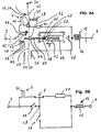
- Fig. 1A and 1B the construction of the schematically illustrated electrical selective self-switch according to the invention in the switched-on operating state and an associated equivalent circuit diagram are shown.
- the self-switch according to the invention has a first electrical terminal 2 and a second electrical terminal 4, between which an auxiliary tripping device 6, a first switch 8, a resistor 10 and a main tripping device 12 are connected in series.
- the electrical selective self-switch according to the invention has a bypass current path which is connected in series with the main tripping device 12 between the first terminal 2 and the second terminal 4 and which has a second switch 14 closed in the event of a malfunction and a normally closed third switch 16 is connected in series with the second switch 14.
- the input contact of the first switch 8 is connected by a current bridge with a connection contact 18 between the second switch 14 and the third switch 16.
- Fig. 1A shows the structure of the electrical selective self-switch according to the invention in the switched-on operating state.
- a pivotally movable contact bridge 20 connects a first fixed contact 22, which forms the input contact of the first switch 8, a second fixed contact 24 which is connected to the resistor 10, and a third fixed contact 26, which via the bypass current path with the main triggering device 12 in connection stands, electrically with each other.
- the contact bridge 20 bears against a contact point 28 at its first end 30 on the second fixed contact 26 and establishes an electrical connection between the main triggering device 12 and the first connection 2 via the second switch 14.
- the contact bridge 20 In the vicinity of its other end 32, the contact bridge 20 is supported via a compression spring 34 against an abutment 38 provided on a switching lock 36.
- the abutment 38 and the third fixed contact 26 lie on the same side of the contact bridge 20. On the side facing away from this side of the contact bridge 20, this lies in a between the point of the compression spring 34 and the third fixed contact 26 on the first fixed contact 22 and the second fixed contact 24 and thus provides an electrical connection between the first, second and third fixed contact 22, 24 and 26 ago.
- the first fixed contact 22 is on the same side of the contact bridge 20 as the second fixed contact 24.
- the second fixed contact 24 slightly further In the operating state, the first contact bridge 20 is supported by the pressure of the spring 34 against the first fixed contact 22 and the third fixed contact 24 and from the force of the spring 34 to a first fixed contact 22nd and the second fixed contact 24 connecting pivot axis X in the detailed representation of Fig. 1A pivoted counterclockwise, so that the first end 30 of the contact bridge 20 is pressed with the contact point 28 against the third fixed contact 26.
- the compression spring 34 thus brings on all three fixed contacts 22, 24 and 26 a required pressure force, which brings the first contact bridge 20 against the fixed contacts 22, 24 and 26 for fixed abutment.
- the electrical selective self-switch according to the invention has a movable contact 40 which electrically connects the first terminal 2 to the contact bridge 20 in the event of a fault.
- the movable contact 40 is mounted with its first end 42 in a pivot bearing 44 and is located with a contact point 46 at its second end 48 to the contact bridge 20 at.
- the pivot axis of the pivot bearing 44 is substantially parallel to the pivot axis X of the contact bridge 20.
- the movable contact 40 is disposed on the same side of the contact bridge 20 as the first fixed contact 22 and the second fixed contact 24, wherein the movable contact 40 against the contact bridge 20th is pressed by a compression spring 50, which is supported on an abutment 52.
- the movable contact 40 thus connects the first terminal 2 with the contact bridge 20 and thus forms the closed second switch 14.
- the third fixed contact 26 opposite a fixed housing stop 54 is provided, to which the first end 30 of the contact bridge 20 during a movement the contact bridge 20 in the clockwise direction against the force of the compression spring 34 abuts to limit a deflection of the contact bridge 20.
- the main triggering device 12 has a coil 56 which is connected in series between the second terminal 4 and the shunt current path to the second switch 14 and the third switch 16.
- the main tripping device 12 which is designed as a magnetic actuator device or magnet system, further comprises a coil core 58 located within the coil 56, a pin 60 and a first magnet armature 62.
- a second armature 64 is provided, which is also displaceable in the release direction B within the coil 56 and acts on the pin 60. At rest, the second armature 64 is supported under the force of a compression spring 66 against a stop 68 fixed to the housing.
- the core 58 is provided on its side facing the first armature 62 end face with a short-circuit ring 70, wherein formed in the short-circuit ring 70, which is made of a highly electrically conductive material, eddy currents that prevent the formation of vibrations in the main triggering device 12 so that there is no unwanted noise. This is particularly advantageous in AC operation, since then the armature is held vibration-free at the core 58 during the triggering of the self-switch.
- the pin 60 is axially slidably mounted within the core 58 in the release direction A and is biased by the compression spring 66 against the release direction B.
- the forward end of the pin 60 protrudes axially from the core 58 toward the contact bridge 20 and the movable contact 40 and forms a striker for actuating the movable contact 40, the point of action of the pin 60 between the pivot bearing 44 of the movable contact 40 and the compression spring 50 is located.
- the pin 60 extends through a through hole 72 of the contact bridge 20, wherein at the front end of the pin 60 in the direction of actuation B of the first armature 62 in front of the contact bridge 20, a widening or an enlarged diameter portion 74 is arranged, which is larger than that Through hole 72 of the contact bridge 20 is.
- the widening 74 abuts against the contact bridge 20 to this about the pivot axis X, which is formed by the first and second fixed contact 22 and 24 against the force of the compression spring 34 counterclockwise to move and to open the contact of the contact bridge 20 with the third fixed contact 26.
- the widening 74 is arranged on the pin 60 such that first the contact between the movable contact 40 and the contact bridge 20 is opened before the contact between the contact bridge 20 and the third fixed contact 26 is opened.
- the rear end of the pin 60 is supported in a blind hole of the second armature 64 against the first armature 62 from.
- the pin 60 penetrates an axial bore in the first armature 62.
- the first magnet armature 62 is axially displaceably guided within the blind hole of the second armature 64 and is supported on its side facing away from the magnet armature 64 against a collar 75 of a portion of the pin 60 with an enlarged diameter from.
- auxiliary release device 6 This has a Bimetallbetuschiger worn with a first bimetal 76, which is connected between the first terminal 2 and the first fixed contact 22 of the first switch 8.
- the switching mechanism 36 In a current flowing through the auxiliary current path, the first bimetal 76 is heated and bends with it, whereupon the switching mechanism 36 is triggered in a known manner after a delay time correlated with the current intensity.
- the switching mechanism 36 moves in the direction of in Fig. 4A shown arrow C, wherein the second end 32 of the contact bridge 20 pivots in a clockwise direction about the axis X until the first end 30 comes to rest against the housing fixed against the third fixed contact 26 stop 54.
- this movement of the switching mechanism 36 and the abutment 38 is moved in the direction of the arrow C, so that the pivotal movement of the contact bridge 20 without compression of the spring 34 takes place, so the force of the spring 34 does not increase additionally.
- the further movement of the switching mechanism 36 in the direction of the arrow C causes the contact bridge 20 to come away from the first fixed contact 22 and from the second fixed contact 24, so that the first switch 8 opens becomes.
- the positioning of the first fixed contact 22 and of the second fixed contact 24 is offset in the release direction C, first the second fixed contact 24 can be detached from the contact bridge 20, after which the first fixed contact 22 is detached from the contact bridge 20, so that the circuit is finally disconnected ,
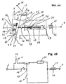
- the coil 56 induces a magnetic force on the first armature 62, the latter in the release direction B against the force of the spring 66 against the collar 75th the pin 60 moves and then the pin 60 against the force of the spring 66 in the release direction B against the movable contact 40 in its point of action, whereby the contact between the movable contact 40 and contact bridge 20 is opened, as in FIGS. 2A and 2B shown.
- the extension 74 is attached to the pin 60 so that the contact bridge 20 still forms a contact with the third fixed contact 26 and is not opened.
- the overcurrent corresponds to a first threshold current, which is adjustable in terms of apparatus (for example, by a corresponding dimensioning of the ratio between the spring force of the spring 66 and the force of the coil 56) by the electrical selective self-switch.
- the electrical selective self-switch can be provided as a main switch, with an occurrence of an overcurrent first by lying after the main switch fuses of End consumers can be eliminated without the working as a main switch electrical selective selector switch disconnects the entire supply of a variety of end users.
- the electrical selective self-switch is intended to actuate the switching mechanism 36 within a very short time, that is to say a second time duration, which is substantially shorter than the first time duration.
- a short-circuit current which in addition to the movable contact 40 by means of the expansion 74, the contact bridge 20 moves in the direction of actuation B and thus the contact between contact bridge 20 and third fixed contact 26 is opened, there is an opening of the second switch 14 as well as the third switch 16, as in the equivalent circuit diagram in FIG Fig. 3B is shown.
- the short-circuit current flows via the first bimetal 76, the first switch 8 and the current-limiting resistor 10 via the coil 56 to the second terminal 4.
- the short-circuit current causes a sudden heating of the first bimetal 76, whereby the switching mechanism 36 is actuated immediately.
- the second armature 64 in the case of a short-circuit shutdown has the task to open the third fixed contact 26 abruptly directly to a Greö Maschinensweg without the interposition of any Kinematikmaschine sufficient to effectively limit the acting on the third fixed contact 26 arc current, so that the arc safely is deleted.
- the second magnet armature 64 is abruptly moved in the release direction B and acts on the system of the rear end of the pin 60 directly on the pin 60 and shifts it in the triggering direction abruptly against the contact bridge 20th
- a further embodiment of the electrical selective self-switch according to the invention.
- the auxiliary tripping device 6 on a Bimetallbetquestionediger founded in addition to the first bimetal 76, a second bimetal 78 which is formed so that it causes independent of the first bimetal 76 by means of the Bimetallbetuschiger Anlagen triggering the switching mechanism 36.
- the second bimetal 78 is in this case connected between the second fixed contact 24 and the coil 56.
- the second bimetal 78 thus becomes active only in the event of a short circuit or when a second threshold current is exceeded, since below one second threshold current, the second bimetal 78 and the resistor 10 is shorted by the shunt current path to the third switch 16.
- the second bimetal 78 has the function that it opens the switching mechanism 36 with a time constant, which is substantially smaller than the time constant of the first bimetal 76th
- the present invention thus provides an electrical selective self-switch which selectively opens in the event of an overcurrent occurring after a period of time sufficient for subsequent electrical self-switches of end-users to shut off before the main switch operating as an electrical selective self-switch turns off, and which in Case of a short-circuit current abruptly the contact between the first terminal 2 and second terminal 4 separates.
- the electric self-switch according to the invention has the advantage that in normal operation, the current between the first terminal 2 and second terminal 4 substantially only flows through the coil 56 of the main triggering device 12, since the first bimetal 76 or the second bimetal 78 through the bypass current path with the second Switch 14 and the third switch 16 are short-circuited.
- the power consumption of the electric selective self-switch according to the present invention is minimized.
- the electric selective self-switch of the present invention has the advantage that before switching off by the switching mechanism 36, an uninterrupted flow of current in an auxiliary current path for controlling the switching mechanism 36 is ensured, whereby a fault in the function of the auxiliary release device is avoided.
- resistor 10 and the coil 56 will be described, based on the 6 and 7 to better illustrate the principle of operation by a simplified main circuit breaker will be explained.
- the arrangement and configuration of the selective resistor 101 and the beating coil 102 are applicable to a resistor 10 configured as a coil and the coil 56.
- resistors in the range of 0.5 ohms are used in the main circuit breaker.
- the selective resistor has to be able to handle powers of the order of 100 kilowatts non-destructively.
- resistor 10 for use, which is wound as a coil of resistance material, over the bobbin of the main circuit, which may be the coil 56, is arranged.
- the Selektivauslöser forms together with the impact coil a structural unit, which is enclosed by a common magnetic yoke and additionally has a magnetic core, a magnet armature and a selective bimetal.
- the magnetic yoke is formed so that it not only serves to conduct the magnetic flux, but also acts as a magnetic and thermal shield against adjacent devices.
- the magnetic yoke which also carries the selective bimetal, encloses on four sides in a box-shaped manner both the impact coil and the coil-shaped selective resistance and is spatially arranged on both sides between the latter and the housing walls of the main automatic circuit breaker.
- winding direction of selective resistance and impact coil is chosen so that complement their magnetic effect in current flow.
- Fig. 6 is the arrangement of the selective resistor 101 on the impact coil 102 can be seen from the circuit diagram of the main circuit breaker. Likewise, the circuit-technical position of the selective release can be recognized as a parallel circuit. The illustrated switching state corresponds to the fault case "short circuit" during the delay time.
- the main contact 103 and the isolating contact 104 are closed.
- the operating current flows through the main contact 103 and the impact coil 102 to the electrical load.
- the isolating contact 104 remains closed, so that the main contact 103 is bridged by the parallel circuit of the selective release.
- the short-circuit current is limited by the selective resistor 101.
- This residual current flows through both the selective bimetal 106 and through the selective resistor 101 and the impact coil 102.
- the residual current generates an additional, magnetic induction in the selective resistance, which strengthens both the tightening force of the armature 105 when opening the main contact 103 in the magnetic circuit of the beating coil also ensures a sufficient holding force of the armature 105 on the magnetic core 108 during the delay time.
- the selective bimetal 106 bends and unlatches the switching mechanism, which then opens the isolating contact 104, the main contact 103 is kept open and thus interrupts the circuit to be protected. If during the delay time the circuit elsewhere, so z. B. is interrupted by a downstream circuit breaker, the main circuit breaker remains switched on and ensures the availability of the rest of the system.
- Fig. 7 schematically is a horizontal section through the main circuit breaker shown in plan view. From this, the spatial arrangement of the selective resistor 101 can be seen over the impact coil 102 and the formation of the magnetic yoke 107 as a thermal and magnetic shield within the housing 110 relative to adjacent devices recognizable.
- the flux in the magnetic circuit is generated both by the number of turns of the selective resistor 101 and by the windings of the beating coil 102, so that the residual current limited by the selective resistance is certainly sufficient for the armature 105 during the delay time to hold the magnetic core 108 and thus to fix the main contact 103 against the force of the closing spring 109 in the open position.
- a Selektivauslöser for a main circuit breaker, which is arranged in series connection of selective bimetal and selective resistor as a parallel circuit to the main contact and bridges this in the event of a fault "short circuit".
- the selective resistor 101 is formed as a coil and arranged in the magnetic circuit of the beating coil 102 for their magnetic assistance in the force effect when opening and keeping open the main contact 103.
- the selective resistor 101 limited in functional combination both the short-circuit current and amplified with the remaining residual current, the flooding in the magnetic circuit together with the impact coil 102nd
- the selective resistor 101 is arranged spatially between the magnet yoke 107 and the impact coil 102, enclosing and covering it at least partially.
- the selective release is circuitally arranged together with the impact coil 102 on the same side in the energy flow direction of the main contact 103 and isolating contact 104.
- the Selektivauslöser forms together with the impact coil 102, the magnetic core 108, the armature 105, the selective resistor 101, the Selektivbimetall 106 and the yoke 107 a structural unit, wherein the yoke which on the housing walls 110 over a large area abuts the attachment for the base of the Selektivbimetalles 106th offers.
- the arrangement of the formed as a coil of selective resistance 101 to the impact coil 102 is according to the invention in the Fig. 1 to 5 shown resistor 10 and the coil 56 applicable.
Landscapes
- Breakers (AREA)
- Electromagnets (AREA)
- Keying Circuit Devices (AREA)
Claims (18)
- Commutateur automatique électrique sélectif, comprenant- un circuit série constitué d'un dispositif de déclenchement auxiliaire (6), d'un premier commutateur (8) normalement fermé, d'une résistance (10) et d'un dispositif de déclenchement principal (12) qui est branché entre une première et une deuxième borne électrique (2, 4),- un circuit de dérivation qui est branché en série avec le dispositif de déclenchement principal (12) entre la première et la deuxième borne électrique (2, 4) et qui présente un deuxième commutateur (14) fermé en l'absence de défaut,
caractérisé en ce
que le commutateur automatique présente un troisième commutateur (16) normalement fermé, qui est branché en série avec le deuxième commutateur (14), et un pont de courant qui relie un contact d'entrée du premier commutateur (8) à un contact de liaison (18) entre le deuxième et le troisième commutateur (14, 16),
le dispositif de déclenchement principal (12) étant configuré de façon que le deuxième commutateur (14) s'ouvre lorsqu'un premier courant de seuil est atteint, et que le troisième commutateur (16) s'ouvre en plus lorsqu'un deuxième courant de seuil, qui est supérieur au premier courant de seuil, est atteint, et
le dispositif de déclenchement auxiliaire (6) étant configuré de façon que le premier et le troisième commutateur (8, 16) s'ouvrent après écoulement d'une première durée lorsque le deuxième commutateur (14) est ouvert, tandis que le premier commutateur (8) s'ouvre après écoulement d'une deuxième durée, qui est plus courte que la première durée, lorsque le deuxième et le troisième commutateur (14, 16) sont ouverts. - Commutateur automatique électrique sélectif selon la revendication 1, caractérisé en ce que le pont de courant est formé par un pont de contact (20) qui, en fonctionnement, relie électriquement entre eux un premier et un deuxième contact fixe (22, 24) du premier commutateur (8) ainsi qu'un troisième contact fixe (26) du troisième commutateur (16).
- Commutateur automatique électrique sélectif selon les revendications 1 ou 2, caractérisé en ce que le troisième contact fixe (26) d'une part et le premier et le deuxième contact fixe (22, 24) d'autre part sont situés sur des côtés opposés l'un à l'autre du pont de contact (20).
- Commutateur automatique électrique sélectif selon les revendications 1, 2 ou 3, caractérisé en ce que le dispositif de déclenchement auxiliaire (6) présente un moyen actionneur à bilame avec un premier bilame (76) situé entre la première borne (2) et le premier commutateur (8), lequel moyen actionneur à bilame est configuré de façon à agir sur un verrou de commutation (36) sollicitant mécaniquement le pont de contact (20), la force de déclenchement exercée par le verrou de commutation (36) sur le pont de contact (20) agissant dans le sens d'ouverture de la connexion entre le troisième contact fixe (26) et le pont de contact (20) et les sens d'ouverture de la connexion entre le premier contact fixe (22) et le pont de contact (20) ainsi qu'entre le deuxième contact fixe (24) et le pont de contact (20).
- Commutateur automatique électrique sélectif selon la revendication 4, caractérisé en ce que le moyen actionneur à bilame présente un deuxième bilame (78) situé entre le premier commutateur (8) et la deuxième borne (4), lequel bilame (78) étant configuré de façon à provoquer un déclenchement du verrou de commutation (36) indépendamment du premier bilame (76) à l'aide du moyen actionneur à bilame.
- Commutateur automatique électrique sélectif selon les revendications 4 ou 5, caractérisé en ce que la disposition du premier contact fixe (22) et du deuxième contact fixe (24) et/ou la configuration du pont de contact (20) est telle que, lors du déclenchement du verrou de commutation (36), après que le troisième contact fixe (26) s'est ouvert, le pont de contact (20) soit séparé d'abord du deuxième contact fixe (24) et ensuite du premier contact fixe (22).
- Commutateur automatique électrique sélectif selon l'une des revendications 2 à 6, caractérisé en ce que le dispositif de déclenchement principal (12) présente un moyen actionneur magnétique agissant mécaniquement sur le pont de contact (20), avec un premier induit magnétique (62) mobile dans le sens d'actionnement et une bobine (56) branchée entre le circuit de dérivation et la deuxième borne (4), la force de déclenchement exercée par le premier induit magnétique (62), dirigée dans le sens d'actionnement (B) du premier induit magnétique (62), agissant dans le sens d'ouverture de la connexion entre le troisième contact fixe (26) et le pont de contact (20) et dans le sens de fermeture de la connexion entre le premier contact fixe (22) et le pont de contact (20) ainsi qu'entre le deuxième contact fixe (24) et le pont de contact (20).
- Commutateur automatique électrique sélectif selon la revendication 7, caractérisé en ce qu'une ligne de liaison (X) entre le premier contact fixe (22) et le deuxième contact fixe (24) forme un axe de pivotement pour le pont de contact (20) lorsque la force de déclenchement du premier induit magnétique (62) est appliquée sur le pont de contact (20).
- Commutateur automatique électrique sélectif selon l'une des revendications 7 à 8, caractérisé en ce que le point d'action de la force de déclenchement exercée par le premier induit magnétique (62) se situe entre le troisième contact fixe (26) d'une part et le premier et le deuxième contact fixe (22, 24) d'autre part.
- Commutateur automatique électrique sélectif selon l'une des revendications 7 à 9, caractérisé en ce qu'un ressort de contact (34) est prévu, qui produit, en fonctionnement, des forces de contact en même temps entre le troisième contact fixe (26) et le pont de contact (20), entre le premier contact fixe (22) et le pont de contact (20) ainsi qu'entre le deuxième contact fixe (24) et le pont de contact (20) dans le sens de fermeture respectif des contacts fixes (22, 24, 26).
- Commutateur automatique électrique sélectif selon la revendication 10, caractérisé en ce que le ressort de contact (34) agit sur le pont de contact (20) sur une partie de celui-ci éloignée du troisième contact fixe (26), dépassant du premier et deuxième contact fixe (22, 24).
- Commutateur automatique électrique sélectif selon l'une des revendications 2 à 11, caractérisé en ce que le deuxième commutateur (14) présente un contact mobile (40) qui relie électriquement la première borne (2) au pont de contact (20) en l'absence de défaut.
- Commutateur automatique électrique sélectif selon la revendication 12, caractérisé en ce que le contact mobile (40) est disposé après le pont de contact (20) dans le sens d'actionnement (B) du premier induit magnétique (62) et monté pivotant au moyen d'un dispositif de pivotement (44), l'axe de pivotement du dispositif de pivotement (44) s'étendant sensiblement parallèlement à l'axe de pivotement (X) du pont de contact (20).
- Commutateur automatique électrique sélectif selon les revendications 12 ou 13, caractérisé en ce que le dispositif actionneur magnétique présente une broche (60) s'étendant à travers un trou traversant (72) du pont de contact (20), avec un élargissement (74) situé avant le pont de contact (20) dans le sens d'actionnement (B) du premier induit magnétique (62), une extrémité avant de la broche (60) du dispositif actionneur magnétique étant adaptée pour agir sur le contact mobile (40) dans le sens d'ouverture de celui-ci et l'élargissement (74) étant adapté pour agir sur le pont de contact (20) dans le sens d'ouverture de celui-ci.
- Commutateur automatique électrique sélectif selon l'une des revendications 7 à 14, caractérisé en ce que le dispositif actionneur magnétique est configuré de façon que lors d'un actionnement du premier induit magnétique (62), la connexion entre le pont de contact (20) et le contact mobile (40) soit ouverte avant la connexion entre le troisième contact fixe (26) et le pont de contact (20).
- Commutateur automatique électrique sélectif selon l'une des revendications 7 à 15, caractérisé en ce que le dispositif actionneur magnétique présente un noyau (58) qui est pourvu d'un anneau de court-circuit (70) tourné vers le premier induit magnétique (62).
- Commutateur automatique électrique sélectif selon l'une des revendications 7 à 16, caractérisé en ce que le dispositif actionneur magnétique présente un deuxième induit magnétique (64) mobile dans le sens d'actionnement (B), qui possède de préférence une masse plus grande que le premier induit magnétique (62) et qui, lors d'une induction plus élevée dans le dispositif actionneur magnétique, produit en complément du premier induit magnétique (62) un déplacement accéléré dans le sens d'actionnement (B).
- Commutateur automatique électrique sélectif selon l'une des revendications précédentes, caractérisé en ce que le dispositif de déclenchement auxiliaire est configuré de façon qu'en cas d'activation manuelle, d'abord le deuxième commutateur (14), puis le premier commutateur (8) et ensuite le troisième commutateur (16) soient fermés.
Applications Claiming Priority (2)
| Application Number | Priority Date | Filing Date | Title |
|---|---|---|---|
| DE102008026813.5A DE102008026813B4 (de) | 2008-06-05 | 2008-06-05 | Elektrischer selektiver Selbstschalter |
| PCT/EP2009/003968 WO2009146900A1 (fr) | 2008-06-05 | 2009-06-03 | Commutateur automatique électrique sélectif |
Publications (2)
| Publication Number | Publication Date |
|---|---|
| EP2286432A1 EP2286432A1 (fr) | 2011-02-23 |
| EP2286432B1 true EP2286432B1 (fr) | 2016-04-13 |
Family
ID=40982289
Family Applications (1)
| Application Number | Title | Priority Date | Filing Date |
|---|---|---|---|
| EP09757283.8A Not-in-force EP2286432B1 (fr) | 2008-06-05 | 2009-06-03 | Commutateur automatique électrique sélectif |
Country Status (4)
| Country | Link |
|---|---|
| EP (1) | EP2286432B1 (fr) |
| CN (1) | CN102047370B (fr) |
| DE (1) | DE102008026813B4 (fr) |
| WO (1) | WO2009146900A1 (fr) |
Families Citing this family (5)
| Publication number | Priority date | Publication date | Assignee | Title |
|---|---|---|---|---|
| DE102011008078A1 (de) | 2011-01-08 | 2012-07-12 | Peter Flohr | Fernschaltbarer selektiver Hauptleitungsschutzschalter |
| EP3048629A1 (fr) * | 2015-01-23 | 2016-07-27 | Jozef Smrkolj | Disjoncteur de protection |
| FR3075458B1 (fr) * | 2017-12-14 | 2020-09-11 | Schneider Electric Ind Sas | Appareil electrique destine a etablir ou interrompre le courant dans un circuit electrique |
| GB2585835B (en) * | 2019-07-16 | 2023-07-19 | Eaton Intelligent Power Ltd | Relay |
| GB2619070A (en) * | 2022-05-26 | 2023-11-29 | Eaton Intelligent Power Ltd | Switching arrangement with a current sensitive latched switching contact and a second non-latched switching contact |
Family Cites Families (8)
| Publication number | Priority date | Publication date | Assignee | Title |
|---|---|---|---|---|
| DE2854616C2 (de) | 1978-12-18 | 1984-03-22 | Brown, Boveri & Cie Ag, 6800 Mannheim | Selektivschutzeinrichtung |
| DE3820993A1 (de) * | 1988-06-22 | 1989-12-28 | Hager Electro Gmbh & Co | Schutzschalter gegen ueberstrom und kurzschluss |
| DE4118377C2 (de) | 1991-06-05 | 1999-03-04 | Hager Electro Gmbh | Leitungs- und/oder Geräteschutzschalter |
| FR2714520B1 (fr) * | 1993-12-24 | 1996-01-19 | Telemecanique | Appareil électrique interrupteur à contacts séparables. |
| EP1365432B8 (fr) * | 2002-05-21 | 2010-05-19 | Hager Electro GmbH & Co. KG | Disjoncteur pour circuit et/ou appareil |
| DE10354505B4 (de) | 2003-11-21 | 2006-01-12 | Eti Elektroelement D.D. | Elektrischer Selbstschalter |
| DE102006037233A1 (de) * | 2006-08-09 | 2008-02-14 | Siemens Ag | Schutzschalter |
| CN100587873C (zh) * | 2007-07-27 | 2010-02-03 | 浙江正泰电器股份有限公司 | 自动转换开关 |
-
2008
- 2008-06-05 DE DE102008026813.5A patent/DE102008026813B4/de not_active Expired - Fee Related
-
2009
- 2009-06-03 WO PCT/EP2009/003968 patent/WO2009146900A1/fr not_active Ceased
- 2009-06-03 CN CN200980119632.7A patent/CN102047370B/zh not_active Expired - Fee Related
- 2009-06-03 EP EP09757283.8A patent/EP2286432B1/fr not_active Not-in-force
Also Published As
| Publication number | Publication date |
|---|---|
| CN102047370B (zh) | 2013-10-30 |
| DE102008026813B4 (de) | 2016-11-17 |
| EP2286432A1 (fr) | 2011-02-23 |
| CN102047370A (zh) | 2011-05-04 |
| WO2009146900A1 (fr) | 2009-12-10 |
| DE102008026813A1 (de) | 2009-12-10 |
Similar Documents
| Publication | Publication Date | Title |
|---|---|---|
| EP2980822B1 (fr) | Appareil de commutation de protection et culasse magnétique | |
| EP0042113B1 (fr) | Interrupteur automatique | |
| DE102013211539B4 (de) | Schaltmechanik und elektromechanisches Schutzschaltgerät | |
| EP2697812B1 (fr) | Dispositif de contact et sa commande pour disjoncteur | |
| EP3248204B1 (fr) | Disjoncteur de protection | |
| EP2286432B1 (fr) | Commutateur automatique électrique sélectif | |
| DE10244961B3 (de) | Selektiver Leitungsschutzschalter | |
| DE69206749T2 (de) | Elektrischer Schützschalter mit Einfügung von zusätzlichen Windungen im Magnetauslöser | |
| EP2263247B1 (fr) | Dispositif de commutation | |
| DE102016203506B4 (de) | Auslösevorrichtung und elektromechanisches Schutzschaltgerät | |
| EP1495477A1 (fr) | Disjoncteur presentant une fonction de coupure de courant de defaut | |
| EP3537466B1 (fr) | Appareil de commutation de protection électromécanique | |
| DE102009031138B4 (de) | Schalteinrichtung | |
| DE102011079593B4 (de) | Elektromechanisches Schutzschaltgerät | |
| DE942455C (de) | Elektrischer UEberstromselbstschalter fuer Wechselstrom | |
| DE102012023914A1 (de) | Zentral sperr-und freischaltbarer Hauptsicherungsautomat | |
| EP2680293B1 (fr) | Mécanisme de déclenchement | |
| EP2824689B1 (fr) | Déclencheur dynamique et commutateur d'installation électrique doté d'un déclencheur dynamique | |
| DE102017202790B4 (de) | Elektromechanisches Schutzschaltgerät | |
| DE102016203508B4 (de) | Auslösevorrichtung und elektromechanisches Schutzschaltgerät | |
| DE2610951B2 (de) | Schutzschalter | |
| DE69833637T2 (de) | Selektiver Auslöser für Leistungsschalter | |
| DE102015203778B4 (de) | Elektromechanisches Schutzschaltgerät und Anordnung | |
| EP0371419A2 (fr) | Disjoncteur électrique | |
| DE102008017273B4 (de) | Elektrischer Selbstschalter |
Legal Events
| Date | Code | Title | Description |
|---|---|---|---|
| PUAI | Public reference made under article 153(3) epc to a published international application that has entered the european phase |
Free format text: ORIGINAL CODE: 0009012 |
|
| 17P | Request for examination filed |
Effective date: 20101223 |
|
| AK | Designated contracting states |
Kind code of ref document: A1 Designated state(s): AT BE BG CH CY CZ DE DK EE ES FI FR GB GR HR HU IE IS IT LI LT LU LV MC MK MT NL NO PL PT RO SE SI SK TR |
|
| AX | Request for extension of the european patent |
Extension state: AL BA RS |
|
| DAX | Request for extension of the european patent (deleted) | ||
| GRAP | Despatch of communication of intention to grant a patent |
Free format text: ORIGINAL CODE: EPIDOSNIGR1 |
|
| INTG | Intention to grant announced |
Effective date: 20150522 |
|
| GRAP | Despatch of communication of intention to grant a patent |
Free format text: ORIGINAL CODE: EPIDOSNIGR1 |
|
| RAP1 | Party data changed (applicant data changed or rights of an application transferred) |
Owner name: HAGER ELECTRO SAS |
|
| INTG | Intention to grant announced |
Effective date: 20151026 |
|
| GRAS | Grant fee paid |
Free format text: ORIGINAL CODE: EPIDOSNIGR3 |
|
| GRAA | (expected) grant |
Free format text: ORIGINAL CODE: 0009210 |
|
| AK | Designated contracting states |
Kind code of ref document: B1 Designated state(s): AT BE BG CH CY CZ DE DK EE ES FI FR GB GR HR HU IE IS IT LI LT LU LV MC MK MT NL NO PL PT RO SE SI SK TR |
|
| REG | Reference to a national code |
Ref country code: GB Ref legal event code: FG4D Free format text: NOT ENGLISH |
|
| REG | Reference to a national code |
Ref country code: AT Ref legal event code: REF Ref document number: 790948 Country of ref document: AT Kind code of ref document: T Effective date: 20160415 Ref country code: CH Ref legal event code: EP |
|
| REG | Reference to a national code |
Ref country code: IE Ref legal event code: FG4D Free format text: LANGUAGE OF EP DOCUMENT: GERMAN |
|
| REG | Reference to a national code |
Ref country code: DE Ref legal event code: R096 Ref document number: 502009012431 Country of ref document: DE |
|
| REG | Reference to a national code |
Ref country code: FR Ref legal event code: PLFP Year of fee payment: 8 |
|
| REG | Reference to a national code |
Ref country code: LT Ref legal event code: MG4D |
|
| REG | Reference to a national code |
Ref country code: NL Ref legal event code: MP Effective date: 20160413 |
|
| PG25 | Lapsed in a contracting state [announced via postgrant information from national office to epo] |
Ref country code: PL Free format text: LAPSE BECAUSE OF FAILURE TO SUBMIT A TRANSLATION OF THE DESCRIPTION OR TO PAY THE FEE WITHIN THE PRESCRIBED TIME-LIMIT Effective date: 20160413 Ref country code: NO Free format text: LAPSE BECAUSE OF FAILURE TO SUBMIT A TRANSLATION OF THE DESCRIPTION OR TO PAY THE FEE WITHIN THE PRESCRIBED TIME-LIMIT Effective date: 20160713 Ref country code: LT Free format text: LAPSE BECAUSE OF FAILURE TO SUBMIT A TRANSLATION OF THE DESCRIPTION OR TO PAY THE FEE WITHIN THE PRESCRIBED TIME-LIMIT Effective date: 20160413 Ref country code: NL Free format text: LAPSE BECAUSE OF FAILURE TO SUBMIT A TRANSLATION OF THE DESCRIPTION OR TO PAY THE FEE WITHIN THE PRESCRIBED TIME-LIMIT Effective date: 20160413 Ref country code: FI Free format text: LAPSE BECAUSE OF FAILURE TO SUBMIT A TRANSLATION OF THE DESCRIPTION OR TO PAY THE FEE WITHIN THE PRESCRIBED TIME-LIMIT Effective date: 20160413 |
|
| PG25 | Lapsed in a contracting state [announced via postgrant information from national office to epo] |
Ref country code: PT Free format text: LAPSE BECAUSE OF FAILURE TO SUBMIT A TRANSLATION OF THE DESCRIPTION OR TO PAY THE FEE WITHIN THE PRESCRIBED TIME-LIMIT Effective date: 20160816 Ref country code: SE Free format text: LAPSE BECAUSE OF FAILURE TO SUBMIT A TRANSLATION OF THE DESCRIPTION OR TO PAY THE FEE WITHIN THE PRESCRIBED TIME-LIMIT Effective date: 20160413 Ref country code: ES Free format text: LAPSE BECAUSE OF FAILURE TO SUBMIT A TRANSLATION OF THE DESCRIPTION OR TO PAY THE FEE WITHIN THE PRESCRIBED TIME-LIMIT Effective date: 20160413 Ref country code: LV Free format text: LAPSE BECAUSE OF FAILURE TO SUBMIT A TRANSLATION OF THE DESCRIPTION OR TO PAY THE FEE WITHIN THE PRESCRIBED TIME-LIMIT Effective date: 20160413 Ref country code: GR Free format text: LAPSE BECAUSE OF FAILURE TO SUBMIT A TRANSLATION OF THE DESCRIPTION OR TO PAY THE FEE WITHIN THE PRESCRIBED TIME-LIMIT Effective date: 20160714 Ref country code: HR Free format text: LAPSE BECAUSE OF FAILURE TO SUBMIT A TRANSLATION OF THE DESCRIPTION OR TO PAY THE FEE WITHIN THE PRESCRIBED TIME-LIMIT Effective date: 20160413 |
|
| PG25 | Lapsed in a contracting state [announced via postgrant information from national office to epo] |
Ref country code: BE Free format text: LAPSE BECAUSE OF NON-PAYMENT OF DUE FEES Effective date: 20160630 Ref country code: IT Free format text: LAPSE BECAUSE OF FAILURE TO SUBMIT A TRANSLATION OF THE DESCRIPTION OR TO PAY THE FEE WITHIN THE PRESCRIBED TIME-LIMIT Effective date: 20160413 |
|
| REG | Reference to a national code |
Ref country code: DE Ref legal event code: R097 Ref document number: 502009012431 Country of ref document: DE |
|
| PG25 | Lapsed in a contracting state [announced via postgrant information from national office to epo] |
Ref country code: EE Free format text: LAPSE BECAUSE OF FAILURE TO SUBMIT A TRANSLATION OF THE DESCRIPTION OR TO PAY THE FEE WITHIN THE PRESCRIBED TIME-LIMIT Effective date: 20160413 Ref country code: DK Free format text: LAPSE BECAUSE OF FAILURE TO SUBMIT A TRANSLATION OF THE DESCRIPTION OR TO PAY THE FEE WITHIN THE PRESCRIBED TIME-LIMIT Effective date: 20160413 Ref country code: CZ Free format text: LAPSE BECAUSE OF FAILURE TO SUBMIT A TRANSLATION OF THE DESCRIPTION OR TO PAY THE FEE WITHIN THE PRESCRIBED TIME-LIMIT Effective date: 20160413 Ref country code: RO Free format text: LAPSE BECAUSE OF FAILURE TO SUBMIT A TRANSLATION OF THE DESCRIPTION OR TO PAY THE FEE WITHIN THE PRESCRIBED TIME-LIMIT Effective date: 20160413 Ref country code: MC Free format text: LAPSE BECAUSE OF FAILURE TO SUBMIT A TRANSLATION OF THE DESCRIPTION OR TO PAY THE FEE WITHIN THE PRESCRIBED TIME-LIMIT Effective date: 20160413 Ref country code: SK Free format text: LAPSE BECAUSE OF FAILURE TO SUBMIT A TRANSLATION OF THE DESCRIPTION OR TO PAY THE FEE WITHIN THE PRESCRIBED TIME-LIMIT Effective date: 20160413 |
|
| REG | Reference to a national code |
Ref country code: CH Ref legal event code: PL |
|
| PLBE | No opposition filed within time limit |
Free format text: ORIGINAL CODE: 0009261 |
|
| STAA | Information on the status of an ep patent application or granted ep patent |
Free format text: STATUS: NO OPPOSITION FILED WITHIN TIME LIMIT |
|
| 26N | No opposition filed |
Effective date: 20170116 |
|
| GBPC | Gb: european patent ceased through non-payment of renewal fee |
Effective date: 20160713 |
|
| REG | Reference to a national code |
Ref country code: IE Ref legal event code: MM4A |
|
| PG25 | Lapsed in a contracting state [announced via postgrant information from national office to epo] |
Ref country code: CH Free format text: LAPSE BECAUSE OF NON-PAYMENT OF DUE FEES Effective date: 20160630 Ref country code: LI Free format text: LAPSE BECAUSE OF NON-PAYMENT OF DUE FEES Effective date: 20160630 |
|
| PG25 | Lapsed in a contracting state [announced via postgrant information from national office to epo] |
Ref country code: IE Free format text: LAPSE BECAUSE OF NON-PAYMENT OF DUE FEES Effective date: 20160603 Ref country code: GB Free format text: LAPSE BECAUSE OF NON-PAYMENT OF DUE FEES Effective date: 20160713 Ref country code: SI Free format text: LAPSE BECAUSE OF FAILURE TO SUBMIT A TRANSLATION OF THE DESCRIPTION OR TO PAY THE FEE WITHIN THE PRESCRIBED TIME-LIMIT Effective date: 20160413 |
|
| REG | Reference to a national code |
Ref country code: FR Ref legal event code: PLFP Year of fee payment: 9 |
|
| REG | Reference to a national code |
Ref country code: AT Ref legal event code: MM01 Ref document number: 790948 Country of ref document: AT Kind code of ref document: T Effective date: 20160603 |
|
| PG25 | Lapsed in a contracting state [announced via postgrant information from national office to epo] |
Ref country code: AT Free format text: LAPSE BECAUSE OF NON-PAYMENT OF DUE FEES Effective date: 20160603 |
|
| PG25 | Lapsed in a contracting state [announced via postgrant information from national office to epo] |
Ref country code: HU Free format text: LAPSE BECAUSE OF FAILURE TO SUBMIT A TRANSLATION OF THE DESCRIPTION OR TO PAY THE FEE WITHIN THE PRESCRIBED TIME-LIMIT; INVALID AB INITIO Effective date: 20090603 Ref country code: CY Free format text: LAPSE BECAUSE OF FAILURE TO SUBMIT A TRANSLATION OF THE DESCRIPTION OR TO PAY THE FEE WITHIN THE PRESCRIBED TIME-LIMIT Effective date: 20160413 |
|
| REG | Reference to a national code |
Ref country code: FR Ref legal event code: PLFP Year of fee payment: 10 |
|
| PG25 | Lapsed in a contracting state [announced via postgrant information from national office to epo] |
Ref country code: TR Free format text: LAPSE BECAUSE OF FAILURE TO SUBMIT A TRANSLATION OF THE DESCRIPTION OR TO PAY THE FEE WITHIN THE PRESCRIBED TIME-LIMIT Effective date: 20160413 Ref country code: MT Free format text: LAPSE BECAUSE OF FAILURE TO SUBMIT A TRANSLATION OF THE DESCRIPTION OR TO PAY THE FEE WITHIN THE PRESCRIBED TIME-LIMIT Effective date: 20160413 Ref country code: IS Free format text: LAPSE BECAUSE OF FAILURE TO SUBMIT A TRANSLATION OF THE DESCRIPTION OR TO PAY THE FEE WITHIN THE PRESCRIBED TIME-LIMIT Effective date: 20160413 Ref country code: MK Free format text: LAPSE BECAUSE OF FAILURE TO SUBMIT A TRANSLATION OF THE DESCRIPTION OR TO PAY THE FEE WITHIN THE PRESCRIBED TIME-LIMIT Effective date: 20160413 Ref country code: LU Free format text: LAPSE BECAUSE OF NON-PAYMENT OF DUE FEES Effective date: 20160603 |
|
| PG25 | Lapsed in a contracting state [announced via postgrant information from national office to epo] |
Ref country code: BG Free format text: LAPSE BECAUSE OF FAILURE TO SUBMIT A TRANSLATION OF THE DESCRIPTION OR TO PAY THE FEE WITHIN THE PRESCRIBED TIME-LIMIT Effective date: 20160413 |
|
| PGFP | Annual fee paid to national office [announced via postgrant information from national office to epo] |
Ref country code: FR Payment date: 20220627 Year of fee payment: 14 |
|
| PGFP | Annual fee paid to national office [announced via postgrant information from national office to epo] |
Ref country code: DE Payment date: 20220629 Year of fee payment: 14 |
|
| REG | Reference to a national code |
Ref country code: DE Ref legal event code: R119 Ref document number: 502009012431 Country of ref document: DE |
|
| PG25 | Lapsed in a contracting state [announced via postgrant information from national office to epo] |
Ref country code: DE Free format text: LAPSE BECAUSE OF NON-PAYMENT OF DUE FEES Effective date: 20240103 |
|
| PG25 | Lapsed in a contracting state [announced via postgrant information from national office to epo] |
Ref country code: FR Free format text: LAPSE BECAUSE OF NON-PAYMENT OF DUE FEES Effective date: 20230630 |