EP2286523B1 - Procédé et appareil de compensation d'une atténuation de liaison satellite due aux intempéries - Google Patents
Procédé et appareil de compensation d'une atténuation de liaison satellite due aux intempéries Download PDFInfo
- Publication number
- EP2286523B1 EP2286523B1 EP09734884.1A EP09734884A EP2286523B1 EP 2286523 B1 EP2286523 B1 EP 2286523B1 EP 09734884 A EP09734884 A EP 09734884A EP 2286523 B1 EP2286523 B1 EP 2286523B1
- Authority
- EP
- European Patent Office
- Prior art keywords
- modcods
- modcod
- utilization
- satellite
- satellite broadcasting
- Prior art date
- Legal status (The legal status is an assumption and is not a legal conclusion. Google has not performed a legal analysis and makes no representation as to the accuracy of the status listed.)
- Not-in-force
Links
- 238000000034 method Methods 0.000 title claims description 43
- 230000005540 biological transmission Effects 0.000 claims description 27
- 238000004891 communication Methods 0.000 claims description 12
- 230000002452 interceptive effect Effects 0.000 claims description 7
- 230000000717 retained effect Effects 0.000 claims description 3
- 238000005259 measurement Methods 0.000 description 53
- 230000014509 gene expression Effects 0.000 description 19
- 230000008859 change Effects 0.000 description 14
- 238000004422 calculation algorithm Methods 0.000 description 10
- 230000000694 effects Effects 0.000 description 9
- 230000015556 catabolic process Effects 0.000 description 8
- 238000012937 correction Methods 0.000 description 8
- 238000006731 degradation reaction Methods 0.000 description 8
- 230000003044 adaptive effect Effects 0.000 description 7
- 230000006978 adaptation Effects 0.000 description 6
- 238000010586 diagram Methods 0.000 description 6
- 238000009826 distribution Methods 0.000 description 6
- 230000007246 mechanism Effects 0.000 description 6
- 230000008569 process Effects 0.000 description 6
- 238000004458 analytical method Methods 0.000 description 5
- 230000001965 increasing effect Effects 0.000 description 5
- 238000012986 modification Methods 0.000 description 5
- 230000004048 modification Effects 0.000 description 5
- 230000009467 reduction Effects 0.000 description 5
- 238000009795 derivation Methods 0.000 description 4
- 238000005562 fading Methods 0.000 description 4
- 238000013459 approach Methods 0.000 description 3
- 238000004364 calculation method Methods 0.000 description 3
- 238000013461 design Methods 0.000 description 3
- 239000000463 material Substances 0.000 description 3
- 238000012935 Averaging Methods 0.000 description 2
- 239000000969 carrier Substances 0.000 description 2
- 238000010276 construction Methods 0.000 description 2
- 230000001419 dependent effect Effects 0.000 description 2
- 238000011161 development Methods 0.000 description 2
- 230000006870 function Effects 0.000 description 2
- 230000035945 sensitivity Effects 0.000 description 2
- 101150012579 ADSL gene Proteins 0.000 description 1
- 102100020775 Adenylosuccinate lyase Human genes 0.000 description 1
- 108700040193 Adenylosuccinate lyases Proteins 0.000 description 1
- 206010003591 Ataxia Diseases 0.000 description 1
- 206010010947 Coordination abnormal Diseases 0.000 description 1
- 241000276457 Gadidae Species 0.000 description 1
- 230000003247 decreasing effect Effects 0.000 description 1
- 230000002542 deteriorative effect Effects 0.000 description 1
- 238000005516 engineering process Methods 0.000 description 1
- 230000002708 enhancing effect Effects 0.000 description 1
- 239000000835 fiber Substances 0.000 description 1
- 238000009432 framing Methods 0.000 description 1
- 208000028756 lack of coordination Diseases 0.000 description 1
- 230000014759 maintenance of location Effects 0.000 description 1
- 230000000116 mitigating effect Effects 0.000 description 1
- 238000005457 optimization Methods 0.000 description 1
- 238000005192 partition Methods 0.000 description 1
- 230000000737 periodic effect Effects 0.000 description 1
- 238000007493 shaping process Methods 0.000 description 1
- 238000004904 shortening Methods 0.000 description 1
- 230000008054 signal transmission Effects 0.000 description 1
- 238000004088 simulation Methods 0.000 description 1
- 238000000638 solvent extraction Methods 0.000 description 1
- 230000003595 spectral effect Effects 0.000 description 1
- 238000003860 storage Methods 0.000 description 1
- 238000012360 testing method Methods 0.000 description 1
- 238000005303 weighing Methods 0.000 description 1
Images


Classifications
-
- H—ELECTRICITY
- H04—ELECTRIC COMMUNICATION TECHNIQUE
- H04B—TRANSMISSION
- H04B7/00—Radio transmission systems, i.e. using radiation field
- H04B7/14—Relay systems
- H04B7/15—Active relay systems
- H04B7/204—Multiple access
- H04B7/212—Time-division multiple access [TDMA]
-
- H—ELECTRICITY
- H04—ELECTRIC COMMUNICATION TECHNIQUE
- H04B—TRANSMISSION
- H04B7/00—Radio transmission systems, i.e. using radiation field
- H04B7/14—Relay systems
- H04B7/15—Active relay systems
- H04B7/185—Space-based or airborne stations; Stations for satellite systems
- H04B7/1851—Systems using a satellite or space-based relay
- H04B7/18513—Transmission in a satellite or space-based system
Definitions
- the present invention relates to a system for compensation for weather-based attenuation in a satellite link and, more particularly, but not exclusively to such compensation wherein a range of modulation levels can be selected.
- the present methods can be used in either one direction, that is forward or return links, or in both directions (forward and return links).
- Weather can cause attenuation to the signal on a satellite communication link.
- the ground to satellite leg may experience different weather conditions from the satellite to ground leg.
- different satellite to ground legs may experience different weather conditions, so that the overall attenuation in the link may not only change rapidly but may differ between different receiving stations at the same instant.
- a recent proposal involves operating the link based on expected daily weather conditions for the specific geographical region in which the link operates. However even in this case transmission power is wasted since the system operates on the basis of the worst case within the time and geographical frame of the estimate.
- AUPC automatic uplink power control
- Adaptive coding and modulation is known to keep the SNR of the channel constant in the face of changing noise levels.
- the modulation pattern is changed between a high capacity modulation at low noise and a low capacity but highly robust modulation when the noise increases.
- the article "DiffServ-based Services-specific VCM in DVB-S2" by Peter Maurutchek discloses a Quality of Service approach for IP services over DVB-S2 links by exploiting DVB-S2 Variable Coding and Modulation capabilities without requiring feedback from the receiving site.
- the method is based on the selection of suitable ModCods for particular information flows depending on their type of service, rather than on the reception quality reported back to the hub station.
- Thesling discloses a process for building physical layer frames with a modcode adapted to the signal quality of a destination terminal. Data packets assigned to the same modcode may be sent to the same frame, although packets associated with higher modcodes may be used to complete a frame before switching to the applicable higher modcode for construction of subsequent frames.
- the article discloses the use of adaptive coding and modulation (ACM) in the new DVB-S2 standard for the interactive service profile, particularly in the satellite downlink.
- European Patent Appl. 1906578A2 by KOREA ELECTRONICS TELECOMM discloses a hierarchical channel adaptive packet scheduling apparatus and method for satellite networks.
- the apparatus includes: at least one hierarchical queue according to class where a packet to be transmitted with each service class of different service levels is queued; at least one queue according to region where a packet to be transmitted to each region having different weather conditions is queued; and a queue controller for transmitting a packet queued to the queue according to class and the queue according to region to a receiving device according to a packet scheduling policy fixed in advance.
- the following documents are representative of the state of the art:
- a satellite broadcasting system for communication between a satellite hub and a range of ground stations in which a set having a predetermined number of MODCODS is available for data transmission from the satellite hub to the ground stations, each MODCOD utilizing resources, the system comprising a MODCOD limiter for limiting the number of MODCODs in operation at a given time to a subset smaller than the predetermined number of MODCODS, thereby reducing overall use of resources.
- the MODCODS range from a minimal configuration to a maximal configuration and wherein the MODCOD limiter is configured to retain a MODCOD having a minimal configuration.
- An embodiment may comprise a utilization unit associated with the MODCOD limiter to direct the MODCOD limiter to retain MODCODS with a higher utilization and discard MODCODS with a lower utilization.
- the MODCOD limiter is configured to modify utilization thresholds of respectively retained MODCODS.
- the ground stations are divided into regions, the MODCOD limiter being configured to retain and discard MODCODS per region.
- An embodiment may comprise a utilization unit associated with the MODCOD limiter to direct the MODCOD limiter to retain MODCODS with a higher utilization and discard MODCODS with a lower utilization, wherein the utilizations are per region.
- the MODCODS range between a minimal configuration and a maximal configuration, the MODCOD limiter being configured to provide each region with the minimal configuration MODCOD irrespective of utilization and at least two other MODCODS based on respectively higher utilization.
- An embodiment may comprise determining overall utilization levels of MODCODs over all regions and replacing MODCODS of low overall utilization with a nearest lower configuration MODCOD of higher utilization.
- a satellite broadcasting method for communication between a satellite hub and a range of ground stations in which a set having a predetermined number of MODCODS is available for data transmission from the satellite hub to the ground stations, each MODCOD requiring resources, the method comprising limiting the number of MODCODs in operation at a given time to a subset smaller than the predetermined number of MODCODS, thereby reducing overall resource usage.
- the MODCODS range from a minimal configuration to a maximal configuration, the method comprising retaining a MODCOD having a minimal configuration.
- An embodiment may involve identifying respective utilization levels of MODCODS and retaining MODCODS with a higher utilization and discarding MODCODS with a lower utilization.
- the ground stations are divided into regions, the method comprising discarding MODCODS per region.
- An embodiment may involve directing the MODCOD limiter to retain MODCODS with a higher utilization and discard MODCODS with a lower utilization, wherein the utilizations are per region.
- An embodiment may involve providing each region with the minimal configuration MODCOD irrespective of utilization and at least two other MODCODS based on respectively higher utilization.
- An embodiment may involve providing an interactive television channel.
- the MODCODS range between a minimal configuration and a maximal configuration, and wherein the ground stations are divided into regions, the method comprising:
- An embodiment may involve determining overall utilization levels of MODCODs over all regions and replacing MODCODS of low overall utilization with a nearest lower configuration MODCOD of higher utilization.
- Implementation of the method and/or system of embodiments of the invention can involve performing or completing selected tasks manually, automatically, or a combination thereof. Moreover, according to actual instrumentation and equipment of embodiments of the method and/or system of the invention, several selected tasks could be implemented by hardware, by software or by firmware or by a combination thereof using an operating system.
- a data processor such as a computing platform for executing a plurality of instructions.
- the data processor includes a volatile memory for storing instructions and/or data and/or a non-volatile storage, for example, a magnetic hard-disk and/or removable media, for storing instructions and/or data.
- a network connection is provided as well.
- a display and/or a user input device such as a keyboard or mouse are optionally provided as well.
- the present embodiments comprise an apparatus and a method which uses measured weather conditions or weather consequential attenuation on the link to modify the link parameters.
- the weather-related attenuation on the uplink meaning the link from the originating ground station to the satellite, is measured, or more accurately estimated from a measure of the overall attenuation, and the uplink power is controlled accordingly to achieve a substantially constant received uplink power.
- the weather related attenuation on the downlink meaning the link from the satellite to the receiving station, is measured, or more accurately estimated from the same measurement as before, and the downlink modulation and coding parameters are modified to compensate for the attenuation and provide a substantially constant receive quality at the receiving station.
- the presently claimed embodiments modify the transmission on the link between the hub and the home, not by modifying the transmission power since this is often not possible, but rather by modifying the MODCOD, that is to say modifying the modulation so that at low attenuation (good weather) high level modulation is used to obtain a high bandwidth channel. At greater attenuations lower level modulation is used to compensate for the greater attenuation and still provide correct reception, but at the cost of bandwidth.
- the hub or part of the hub involved in the particular transmission however does not operate using endless MODCODS for all of its links. Rather, according to the present embodiments the total number of MODCODs in use at any given time is limited, and the limitation follows a scheme which looks for the best efficiency from the MODCODs chosen.
- the present embodiments involve enhancing a VSAT star network based on a single carrier time multiplexed outbound channel (e.g. DVB-S2), with combined AUPC (Automatic Uplink Power Control) and ACM (Adaptive Coding and Modulation) capabilities in order to optimize satellite resources utilization.
- the AUPC is designed to maintain constant satellite transmitted power in all weather conditions by dynamically adapting the transmitted carrier level to the uplink rain attenuation.
- the ACM capability is designed to maintain constant received signal quality at each terminal by dynamically adapting the modulation and coding assigned to the packets transmitted to each terminal to the downlink rain degradation affecting this terminal.
- the present embodiments disclose a satellite broadcasting system for communication between a satellite hub and a range of ground stations in which a set having a predetermined number of MODCODS is available for providing data transmission from the satellite hub to the ground stations.
- the set of MODCODS or modulation and encoding combinations is generally set by the satellite broadcast standard being used, and the broadcaster has the freedom to choose which MODCODS to select.
- the MODCODS may be selected dynamically depending on the conditions and a favored way to deal with deteriorating weather conditions is to use a slower but more robust MODCOD so as to send less data but ensure that it can be read at the destination.
- Any given data is thus queued, encoded and broadcast for the particular MODCOD in force at its region. If too many MODCODS are in use at the same time then traffic related to low utilization MODCODs suffer from large and varying delay. Alternatively, if the allowed maximum delay is limited, the efficiency degrades as blocks assigned to low utilization MODCODS may be transmitted partially empty at a higher pace than necessary.
- the present embodiments thus provide a MODCOD limiter, part of control 30 in FIG. 2 discussed below, for limiting the number of MODCODs in operation at a given time.
- the MODCODS may range from a minimal configuration, meaning minimal data rate with maximal error correction for really bad conditions, to a maximal configuration with high data rate and little error correction for ideal conditions.
- the MODCOD limiter may retain the minimal configuration MODCOD for all regions and discard selected higher configuration MODCODS.
- the minimal configuration may vary in the circumstances.
- the minimal configuration for a particular link may be a different MODCOD from that of a different link and neither of them need be the lowest configuration provided by the standard.
- a utilization unit may direct the MODCOD limiter to retain MODCODS with a higher utilization and discard MODCODS with a lower utilization. Discarding per utilization is on the basis that if a particular MODCOD is utilized say only 1% of the time, then discarding it will have little effect on performance.
- MODCODs are retained and discarded per region, since different regions may be undergoing different conditions. Nevertheless even if retention and discarding is per region, it may be desirable to control the number of MODCODS overall in the system.
- the MODCOD limiter may provide each region with the minimal configuration MODCOD irrespective of utilization and say two or three other MODCODS based on respectively high utilization.
- One or more of the channels being broadcast may be an interactive television channel.
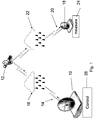
- FIG. 1 illustrates a controlled satellite link, according to a first preferred embodiment of the present invention.
- a hub 10 transmits a signal to a satellite 12 over an uplink 14.
- the uplink encounters rain and clouds 16 which cause weather-related attenuation of the signal. It will be appreciated that weather conditions can change rapidly so that the overall attenuation of the uplink is itself liable to change rapidly.
- the satellite 12 relays the signal it has received on the uplink to one or more ground-based receiving stations 18 via a downlink 20.
- the downlink 20 is also liable to weather based attenuation, which may be brought about by rain and clouds 22. It will be appreciated that the dynamic variation in attenuation on the downlink tends to add to any attenuation on the uplink and also tends to vary independently. It is noted that the uplink attenuation is present in all received signals since there is only one uplink in the present embodiment, but the downlink attenuation varies.
- a reference unit 24 is inserted at a receiving station for measuring signal attenuation over the link.
- the measured attenuation is transmitted back to the hub 10 where a control unit 26, controls a link transmission parameter to dynamically compensate for changes in the measured signal attenuation.
- the reference unit 24 informs the control unit, which then either strengthens the signal or makes the coding or modulation or both more robust so that the received signal remains readable.
- FIG. 1 only a single ground-based receiving station is shown, although it will be appreciated that most satellites relay to multiple ground stations.
- the satellite link may be a broadcast link, and there may therefore be numerous ground-based receiving stations spread over a substantial region. In any event different weather conditions may apply to different receiving stations.
- FIG. 2 illustrates a further embodiment of the present invention in which the link of FIG. 1 is modified to provide separate control over the uplink and the different down links.
- Parts shown in hashed lines may be regarded as theoretical since the ability to make modifications to the satellite 12 is limited and practical implementations are explained below. Specifically items shown in dashed lines indicate features which one would like to include at the satellite, but in practice this is not possible and a system of indirect measurement is discussed below.
- Separate reference units are provided for the uplink and all or some of the different down links.
- Reference unit 28 is theoretically provided at the satellite for independent measuring of attenuation at the uplink, and control unit 26 independently compensates for uplink attenuation.
- Reference unit 24 measures attenuation on the downlink and control unit 30 at the satellite independently compensates for changes in the measured attenuation at the downlink. In practice reference unit 24 is all that is available, so that uplink attenuation is derived from the measurements at reference unit 24, as will be described in greater detail hereinbelow.
- beacon transmitted at a different frequency with constant power towards the earth. Based on received beacon signal level the uplink attenuation can be estimated after taking into account the frequency difference between the beacon and the signal transmission.
- a reference unit is provided at each receiving station and the signal to each ground-based receiving station is independently controlled.
- the various downlinks may be aggregated on a regional basis. That is all downlinks in a certain geographical area may be compensated together based on local weather as measured at one or two of the receiving stations in the region.
- Parameters used in transmission channels are numerous and many such parameters can be adjusted to overcome attenuation.
- One such parameter is transmitted power. In case of severe attenuation the transmission power can be increased. Increased transmission power is generally only available from the hub 10 however. The satellite has only limited power resources and thus increases in transmission power for the down link are not really practical.
- Other parameters that can be modified are coding and modulation parameters. The complexity or robustness of the coding and/or modulation of the signal can be adjusted to maintain received signal quality.
- FIG. 3 is a simplified diagram showing an uplink 32 in which the controlled transmission parameter is transmission power.
- a downlink 34 is shown in which adaptive coding and modulation are provided to ensure the quality of the received signal is maintained. It will be appreciated that compensation for attenuation by modifying the coding and modulation parameters to make the coding and modulation more robust leads to a reduction in the signal rate. Thus picture quality may have to be degraded, and say high definition television HDTV quality may be lost over the duration of a bad weather episode. However as long as the degradation is restricted to the bad weather episode due to dynamic measuring of the signal then the disruption to the customer is minimized.
- the throughput of a site can be maintained even in varying rain conditions and accordingly varying modulation and coding parameters.
- the network design may take into account a distribution of modulation and coding parameters according to climate statistics over the region. When a specific site uses more robust parameters it does not have to reduce throughput but it can consume a larger fraction of the total carrier, while other sites may use less robust parameters at the same time and therefore consume a smaller fraction of the carrier. For a large network the actual aggregated throughput may be similar to the calculated average throughput with very small variance.
- FIG. 4 shows in greater detail how the invention may be applied in practice to a broadcast type satellite link with a single hub and multiple receiving stations in which modifications to the satellite are not possible.
- hub 10 broadcasts to satellite 12 which relays the signal to ground-based receiving stations 18.1 ... 18.n.
- Each ground-based receiving station has different weather conditions.
- the SNR at each receiving station is measured by a measurement unit 24.1...24.n.
- the measurements are then fed via return links, which are typically satellite links or ground links 38, say ADSL over a telephone network, to AUPC and ACM controller 40.
- the AUPC and ACM controller then interacts with ACM modulator 42 and both the controller 40 and modulator 42 interact with traffic shaper 44 to modify the signal that is sent over the link.
- Two independent measurements of SNR and received signal level are performed by a reference ground station or alternatively measurements of forward link and return link SNR of a reference ground station.
- the two measurements are considered together and enable estimations of the uplink and the downlink attenuation separately.
- the measurements from different ground stations are also considered together.
- Uplink attenuation can be used to average the uplink result and downlink attenuation is attributed to the different downlinks.
- the present embodiments provide for coordination between the mechanisms that compensate for uplink and downlink variations in the attenuation. Compensation for the uplink by changing the transmitted power affects the measurements performed by the ground station and the selection of modulation and coding parameters.
- a method of controlling a satellite link comprising: measuring attenuation over the link, and dynamically adjusting at least one of the transmission parameters to compensate for changes in the measured attenuation.
- attenuation may treated per leg, that is per uplink and per downlink, but in such a case, because the satellite itself cannot be modified, the effects at each separate link have to be derived.
- the presently derived approach may also be used for other ACM capable Outbound signals and also for point-to-point SCPC (Single Channel Per Carrier) satellite links.
- the embodiments use communication channel measurements, to allow location and beam independent, real time operation, of the combined AUPC and ACM processes.
- the channel measurements are used for estimating dependent or independent uplink and downlink rain attenuation and degradation. These estimations are then used for making the decisions on the compensations required in the uplink and in the downlink.
- Case I involves a reference terminal installed at the teleport.
- Case II involves reference terminals anywhere, namely either at the teleport or other locations in the same beam, or at other locations in a different beam.
- Case III involves a return link via the satellite. This contrasts with FIG. 4 above, where the return link was terrestrial.
- the return link provides measurements that are used together with forward link measurements for estimating the uplink and downlink attenuation.
- the return link can be either via satellite or terrestrial and is used for forwarding the measurements made by the ground station relating to the link from the ground station to the hub.
- the present embodiments may be used for AUPC only, for example where ACM is not supported by terminals or not activated.
- the embodiments may be used for ACM only, for example where a beacon receiver is used for uplink power control, or uplink is transmitted via C band beam, or the transponder operates at ALC - Automatic Level Control mode.
- the embodiments may involve combined AUPC and ACM operating together to achieve optimal utilization of transponder resources.
- the present embodiments provide a controller that compensates in real time for independent atmospheric and other variations in both uplink and downlink of a satellite communications link.
- a link may be either the multiplexed Outbound carrier of a star VSAT network, or a point-to-point SCPC satellite link.
- the compensation is performed for the uplink by controlling the transmitted power in order to maintain constant satellite transmitted power at all weather conditions.
- the compensation is based on assigning appropriate modulation constellation and code rate which can provide the maximal throughput for the actual weather conditions.
- the controller algorithm uses channel measurements performed by the receiving stations that are sent back to the controller.
- the receiving stations are standard stations that provide service and can be anywhere, under any beam of the satellite. Measurements performed by several or all stations can be used for improving the channel estimations.
- the uplink control is designed to maintain constant satellite transmitted power at all weather conditions by adapting the transmitted carrier level to the uplink rain attenuation.
- the adaptation of coding and modulation is designed to maintain constant received signal quality at each terminal according to the downlink rain degradation affecting this terminal.
- the adjustment for each terminal is implemented by the modulator by transmitting, using time-division multiplexing, a sequence of frames, where the coding and modulation format may change frame-by-frame. Each frame may carry traffic to terminals that expect the coding and modulation levels assigned to that frame.
- the uplink and down link adaptation are based on the same channel measurements.
- the present embodiments may separate the effects of the uplink and down link as reflected from the channel measurements performed by the receiving stations.
- the present embodiments perform combined control of uplink and downlink by deducting the effect of the uplink control from the current channel measurements in order to allow for computing the downlink control stage using the same current measurements.
- Such a technique reduces the control cycle time and the number of modulation and coding corrections as there is no need to wait for the next updated measurements that would be affected by the uplink update for correctly updating the downlink modulation and coding.
- the above approach avoids repeating transmissions from all ground stations requesting to change selection of modulation and coding before and after uplink power modification, and saves time for achieving stable selection. Consequently smaller margins are required and satellite resources are saved.
- the channel estimations produced by the above process namely uplink and down link attenuations can be used, after appropriate correction according to up/down frequency ratios, to additionally control the return links of a star VSAT network (or the return link of the SCPC link).
- the controller instructs each VSAT to increase/ decrease its power level in order to compensate for changes in the estimates of the Return link uplink attenuation. If the VSAT EIRP is already fully exploited and the uplink rain-linked fading is not fully compensated, then compensation may be achieved by a reduction in transmission rate and/ or modulation and coding, and the spare power may then be assigned to other more powerful VSATs, so that the total power consumed from any transponder is maintained at a constant level.
- the controller may also instruct a modification of the transmission rate, modulation and coding in order to compensate the changes in downlink rain attenuation. Compensation may be based on either the already estimated downlink rain degradation or the measured return link signal to noise ratio. Compensation should be after deduction of the uplink power compensation.
- Another consideration that may be taken into account by the controller is to achieve balanced resource utilization, namely appropriate selection of modulation codes or MODCODs for the return links. That is to say the controller may wish to balance the consumed power and bandwidth resources from a transponder which contains the return links with or without the Outbound link. Balancing is based on having a selection of a few MODCODs for the return links where the higher MODCODs consume more power equivalent bandwidth (PEB) than bandwidth, while the lower MODCODs consume more bandwidth than PEB.
- PEB power equivalent bandwidth
- the controller may assign MODCODs according to traffic requirements, weather conditions, satellite coverage, and balancing requirements so that overall balancing may be achieved. Such operation of the controller enables to use all available resources in an efficient way.
- Figure 6 is a graph showing the result of such balancing.
- the controller takes into account that generally the return links are sensitive mainly to uplink fading and not to downlink fading as the CNR in the downlink is generally much larger that in the uplink due to the use of a large teleport antenna. Therefore in the design of the balanced operation the assignment of MODCODs is mainly according to overall network traffic in the return links that may be delivered with specific MODCOD.
- the controller uses ACM and TRC (Transmission Rate Control) to compensate for the limitation of the remote terminal in terms of EIRP for severe rain conditions at the terminal site and for increasing the transmission rate beyond the committed rate to best effort based rates.
- ACM and TRC Transmission Rate Control
- the concept is applicable to any form of modulation that the return channel may use.
- it is applicable for both FDMA and TDMA type return channels, where for TDMA the terminals have to be moved among carriers with different MODCODs or instantaneous transmission rate when the controller decides to change their MODCOD or their instantaneous transmission rate.
- the controller algorithm is as follows for three active MODCODs, but can be extended to any number of MODCODs:
- L fs,dn (dB) is the free space loss between the satellite and the reference VSAT at frequency f dn (Hz) transmitted from the satellite
- a dn (dB) is the downlink rain attenuation
- (G / T) ref (dB/K) is the figure of merit of the receiving reference terminal
- k B -228.6 dBW/HzK is the Boltzmann constant.
- C N o E b N o + 10 ⁇ log R s ⁇ MOD ⁇ COD ⁇ dBHz
- R s is the symbol rate
- MOD is log 2 ( ) of the modulation constellation size
- COD is the code rate
- the term 'linkbudget' refers to the accounting of all of the gains and losses from the transmitter, through the medium (free space, cable, waveguide, fiber, etc.) to the receiver in a telecommunication system. It accounts for the attenuation of the transmitted signal due to propagation, as well as the antenna gains, feedline and miscellaneous losses.
- Table 1 A LinkBudget for a typical Satellite link.
- Link Tx Location Tx Antenna Size (m) BUG (Watt) BUG OBO (db) Rx Antenna Size (m) Data Rate (Kbps) Modul ation FEC FEC TYPE BER Space Segmant (KHz) Rain Availability Margin (dB) %Power of Transponder %BW of Transponder Clear Sky Margin (dB) Outbound Best MODCOD Teleport 9.10 400.00 16.16 1.20 52000.00 16APSK 0.667 LDPG 1.E-08 23400.
- the solution for Case II is based on using measurements performed at the reference VSAT of both CNR (Carrier to Noise Ratio) and SIGL, the received signal level.
- the measurements can be reported either through a return link or any other communication link.
- the instantaneous CNR and SIGL can be read from the receiver chipset which is typically composed of a tuner (e.g. STB6100) and a demodulator (e.g. STB0900).
- a tuner e.g. STB6100
- a demodulator e.g. STB0900
- the last step of the algorithm is useful also for reducing the effect of reference VSAT pointing loss.
- the algorithm cannot distinguish between rain and variations in pointing loss. Therefore, such variations in pointing loss of the teleport antenna or the reference terminals may be interpreted erroneously as uplink rain attenuation as they do not affect the VSAT noise level.
- the weighted average step can reduce the VSAT pointing loss effect as the pointing loss varies independently from VSAT to VSAT.
- the solution for Case III is based on using measurements performed at both ends of the link, e.g. at the Teleport and at the reference VSAT (or at both ends of SCPC link) of received CNR (Carrier to Noise Ratio) for both Forward and Return links.
- the measurements can be reported either through the return link or any other communication link.
- the rain attenuation in the uplink is related to the rain attenuation in the downlink, with a factor K T for the teleport side and a factor K V for the VSAT side, as follows:
- a up F K T + A dn R dB
- a up R K V + A dn F dB
- the ACM mechanism can be operated to compensate for both uplink and down link fades, or for downlink compensation independently, see Lawrence W. Krebs et al., "Methods and Apparatus For Mitigating Rain Fading Over Satcom Links Via Information Throughput Adaptation", US Patent Application Publication 2003/0054816, Filed August 8, 02 ; ETSI EN 302 307 V1.1.1 (2004-01) :"Digital Video Broadcasting (DVB) Second generation framing structure, channel coding and modulation systems for Broadcasting, Interactive Services, News Gathering and other broadband satellite applications"; and Alberto Morello, Vittoria Mignone, "DVB-S2: The Second Generation Standard for Satellite Broad-band Services", Proceedings of the IEEE, vol. 94, no.
- beacon receiver is used for uplink power control, or uplink is transmitted via a C band beam, or the transponder operates at ALC - Automatic Level Control mode.
- the ACM mechanism can alternatively be combined with AUPC.
- the present embodiments provide a combined AUPC and ACM controller designed to achieve overall optimization based on allowed usage of satellite resources.
- the controller algorithm uses channel measurements performed by the receiving stations that are sent back to the controller.
- the receiving stations are standard stations that provide service and can be located anywhere, under any beam of the satellite. Measurements performed by several or all stations can be used for improving the uplink channel estimations.
- the uplink control is designed to maintain constant satellite transmitted power at all weather conditions by adapting the transmitted carrier level to the uplink rain attenuation.
- the adaptation of coding and modulation is designed to maintain constant received signal quality at each terminal according to the downlink rain degradation affecting this terminal.
- the adjustment for each terminal is implemented by the modulator by transmitting, in time-division multiplex, a sequence of frames, where the coding and modulation format may change frame-by-frame.
- the traffic of a terminal that was assigned a specific MODOCD - see table 2 below, may be transmitted in the appropriate frame.
- the uplink and down link adaptation are based on the same channel measurements.
- the present embodiments may separate the effects of the uplink and down link as reflected from the channel measurements performed by the receiving stations.
- the present embodiments perform combined control of uplink and downlink by deducting the effect of the uplink control from the current channel measurements in order to allow for computing of the downlink control stage using the same current set of measurements. This reduces the control cycle time and the number of modulation and coding corrections as there is no need to wait for the next updated measurements that would be affected by the uplink update for correctly updating the downlink modulation and coding.
- FIG. 4 already referred to above shows the scheme of an AUPC & ACM Management system, comprising the AUPC & ACM Controller 40, the ACM modulator 42, which includes the upconverter and the HPA - High Power Amplifier, the Earth station 10, and the satellite 12.
- the satellite terminals (VSAT) 18.1...18.n are connected to the AUPC & ACM Controller via return links.
- the terminals submit the CNR and SIGL measurements to the Controller.
- the ACM modulator operates at constant symbol rate, since the available transponder bandwidth is assumed to be constant.
- ACM is implemented by the modulator by transmitting, in time-division multiplex, a sequence of frames, where the coding and modulation format may change frame-by-frame.
- Each frame can carry traffic to terminals that know to expect the coding and modulation levels assigned to that frame. Therefore, service continuity is achieved, during rain fades, by reducing user bits while increasing, at the same time, the FEC redundancy and/or modulation ruggedness.
- Physical layer adaptation is achieved as follows.
- the AUPC and ACM update cycle is composed of the following stages:
- Both AUPC and ACM update can be performed on the same set of channel measurements thus reducing the cycle period. Shortening the cycle period allows the required margin to be decreased. That is more efficient use is made of the scarce satellite resources allocated for compensating for fast rain fading. Otherwise if only AUPC is performed initially, ACM may be performed on a later measurement of channel status taken after the AUPC update already affected the measurements.
- a typical table with selection of MODCODs for DVB-S2 is shown as Table 2 below.
- a typical example for a MODCOD threshold table showing the upper and lower thresholds for selecting a MODCOD is given in Table 3 below.
- the (CNR) ranges for neighbor MODCODs are partly superposed in order to reduce number of MODCOD switching when (CNR) is near the border between two MODCODs.
- the combined process of AUPC and ACM is shown in the flow chart of FIG. 5 .
- Periodic polling is carried out of all VSATs (receiving stations). On periodical Polling of all VSATs. Interrupts are generated by individual VSATs and occur between Polling events when the particular VSAT needs to correct its MODCOD for maintaining its received signal quality.
- each individual VSAT can calculate the current downlink attenuation based on expression (B.16) and determine if the variation it has measured in its CNR corresponds also to downlink attenuation variation or only to uplink attenuation variation. In the latter case a VSAT, which is not a reference terminal, will not issue an interrupt with a request for MODCOD change but will wait for the AUPC to compensate for the uplink attenuation variation.
- the combined process of AUPC and ACM, as shown in FIG. 5 is based on periodical Polling of all VSATs and obtaining interrupts generated by individual VSATs between Polling events when the VSAT needs to correct its MODCOD for maintaining its received signal quality.
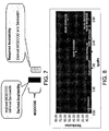
- FIG. 7 is a simplified diagram illustrating MODCOD and bandwidth relationships.
- FIG. 7 is a simplified diagram illustrating MODCOD and bandwidth relationships.
- Stage 1 Partition the service territory into regions characterized by significantly different satellite coverage strength and/or climate conditions. Select two MODCODs per each such region by assuming two modes of operation, Mode 1: “Highest MODCOD” (HMC) which can be used in the region based on the satellite EIRP and earth stations capabilities, for near to clear sky conditions, and the availability that corresponds to such a MODCOD, called “Derived Availability” (A HMC ). Typically the availability that reflects near to clear sky conditions will be about 95%.
- Mode 2 “Required Availability” (A RQ ) and the corresponding “Derived MODCOD” (DMC) that can satisfy such availability.
- a RQ Required Availability
- DMC "Derived MODCOD”
- the ACM based carrier e.g. DVB-S2
- DVB-S2 The ACM based carrier
- Each block has a fixed MODCOD for the traffic carried in it.
- the traffic that waits for transmission in the buffer is waiting for a block with the appropriate MODCOD. If the number of MODCODs is large there are many queues of traffic waiting for a turn to be transmitted. Traffic with a rarely used MODCOD may indeed have to wait a long time until their turn comes. There will be large variations in the delay which are not suitable for interactive applications.
- Figure 8 describes the distribution of MODCODs.
- This distribution is generated by weighing each MODCOD with its activity factor (availability for HMC or Delta availability for DMC) and with the traffic fraction using it, namely the traffic per that region scaled by the total traffic. Actually we can reduce at this stage the number of MODCODs to those selected in the analysis described above and achieve the performance obtained by the analysis. In the case study shown here six different MODCODs are needed.
- Stage 2 Further reduction of the number of MODCODs in order to eliminate MODCODs with low utilization.
- a method for further reduction in the number of MODCODs can be based on using the set of MODCODs selected in Stage 1 and eliminating those of low utilization, e.g. less than 1% of the time.
- the rule is that traffic that needs a certain MODCOD may fall to the next low allowed MODCOD.
- the lowest MODCOD should be kept in the allowed list.
- two of the six MODCODs that remained after Stage 1 may be eliminated with insignificant degradation in the system efficiency.
- FIG. 9 illustrates a series of MODCODs each with different levels of traffic.
- C N o EIRP sat - L fs , dn - A dn + G T ref - k B dBHz
- EIRP i + 1 EIRP sat - A up , i + 1 + G upc , i dBW
- T rain 278K
- T ref T antenna /1.12+290*0.11+ T LNB (K) See Maral and Bousquet pp.191-192.
- L fs,dn (dB) is the free space loss between the satellite and the reference VSAT at frequency f dn (Hz) transmitted from the satellite
- a dn (dB) is the downlink rain attenuation
- G ref (dB) is the gain of the reference terminal antenna
- a Rx is the receiver RF/IF chain loss. It is assumed that the CNR at the uplink is high and all the EIRP sat transmitted by the satellite is used only by the desired signal.
- EIRP i + 1 EIRP sat - A up , i + 1 + G upc , i dBW .
- C N o EIRP sat - L fsdn - A dn + G T ref - k B dBHz .
- EIRP i + 1 EIRP sat - A up , i + 1 + G upc , i dBW .
- EIRP sat is the satellite EIRP that should be maintained constant
- a up,i+ 1 is the rain attenuation at the i +1 iteration
- G upc,i is the control gain applied at the i - th iteration. Consequently the received ( C / N o ) will become:
- C N o i + 1 EIRP i + 1 - L fs , dn - A dn , i + 1 + G T ref , i + 1 - k B dBHz .
Landscapes
- Engineering & Computer Science (AREA)
- Computer Networks & Wireless Communication (AREA)
- Signal Processing (AREA)
- Physics & Mathematics (AREA)
- Astronomy & Astrophysics (AREA)
- Aviation & Aerospace Engineering (AREA)
- General Physics & Mathematics (AREA)
- Radio Relay Systems (AREA)
Claims (15)
- Système de diffusion par satellite dans le cadre d'une communication entre un concentrateur de satellite et un ensemble de stations terrestres, dans lequel un ensemble présentant un nombre prédéterminé de schémas de modulation et codage, MODCODs, est disponible en vue d'une transmission de données, du concentrateur de satellite, par l'intermédiaire du satellite, à des stations terrestres, chaque MODCOD utilisant des ressources, le système étant caractérisé par :un limiteur de MODCOD pour limiter le nombre de MODCODs en fonctionnement à tout instant donné à un sous-ensemble respectif dont le nombre est inférieur audit nombre prédéterminé de MODCODs, ce qui permet de réduire par conséquent l'utilisation globale de ressources ; etune unité d'utilisation associée audit limiteur de MODCOD, configurée de manière à ordonner audit limiteur de MODCOD de limiter ledit sous-ensemble de MODCODs en fonctionnement, en conservant, dans ledit sous-ensemble, une pluralité de MODCODs présentant une utilisation supérieure et en écartant dudit sous-ensemble les MODCODs présentant une utilisation inférieure ;moyennant quoi un MODCOD est écarté dudit sous-ensemble si son utilisation sur un temps défini est inférieure à une fraction de temps prédéterminée.
- Système de diffusion par satellite selon la revendication 1, dans lequel les MODCODs varient entre une configuration minimale et une configuration maximale, et dans lequel ledit limiteur de MODCOD est configuré de manière à conserver un MODCOD présentant une configuration minimale.
- Système de diffusion par satellite selon la revendication 2, dans lequel ledit limiteur de MODCOD est configuré de manière à modifier des seuils d'utilisation de MODCODs respectivement conservés.
- Système de diffusion par satellite selon la revendication 1, dans lequel lesdites stations terrestres sont divisées en zones, ledit limiteur de MODCOD étant configuré de manière à conserver et à écarter des MODCODs par zone.
- Système de diffusion par satellite selon la revendication 4, dans lequel lesdites utilisations sont classées par zone.
- Système de diffusion par satellite selon la revendication 5, dans lequel les MODCODs varient entre une configuration minimale et une configuration maximale, ledit limiteur de MODCOD étant configuré de manière à fournir à chaque zone le MODCOD de configuration minimale indépendamment de l'utilisation, et au moins deux autres MODCODs, sur la base d'une utilisation respectivement supérieure.
- Système de diffusion par satellite selon la revendication 6, dans lequel ladite unité d'utilisation est en outre destinée à déterminer des niveaux d'utilisation globaux de MODCODs sur la totalité des zones, et à ordonner audit limiteur de MODCOD de remplacer des MODCODs présentant une utilisation globale faible par un MODCOD de configuration inférieure la plus proche présentant une utilisation supérieure.
- Procédé de diffusion par satellite dans le cadre d'une communication entre un concentrateur de satellite et un ensemble de stations terrestres, dans lequel un ensemble présentant un nombre prédéterminé de schémas de modulation et codage, MODCODs, est disponible en vue d'une transmission de données, du concentrateur de satellite, par l'intermédiaire du satellite, à des stations terrestres, chaque MODCOD utilisant des ressources, le procédé comportant l'étape ci-dessous consistant à :limiter le nombre de MODCODs en fonctionnement à tout instant donné à un sous-ensemble respectif dont le nombre est inférieur audit nombre prédéterminé de MODCODs, ce qui permet de réduire par conséquent l'utilisation globale de ressources, en :moyennant quoi un MODCOD est écarté dudit sous-ensemble si son utilisation sur un temps défini est inférieure à une fraction de temps prédéterminée.identifiant des niveaux d'utilisation respectifs desdits MODCODs ; eten conservant, dans ledit sous-ensemble, une pluralité de MODCODs présentant une utilisation supérieure et en écartant dudit sous-ensemble les MODCODs présentant une utilisation inférieure ;
- Procédé de diffusion par satellite selon la revendication 8, dans lequel les MODCODs varient entre une configuration minimale et une configuration maximale, le procédé consistant à conserver un MODCOD présentant une configuration minimale.
- Procédé de diffusion par satellite selon la revendication 8, dans lequel lesdites stations terrestres sont divisées en zones, le procédé consistant à écarter des MODCODs par zone.
- Procédé de diffusion par satellite selon la revendication 10, dans lequel lesdites utilisations sont classées par zone.
- Procédé de diffusion par satellite selon la revendication 11, consistant à fournir, à chaque zone, le MODCOD de configuration minimale, indépendamment de l'utilisation, et au moins deux autres MODCODs, sur la base d'une utilisation respectivement supérieure.
- Procédé de diffusion par satellite selon la revendication 8, consistant à fournir une chaîne de télévision interactive.
- Procédé de diffusion par satellite selon la revendication 8, dans lequel les MODCODs varient entre une configuration minimale et une configuration maximale, et dans lequel lesdites stations terrestres sont divisées en zones, le procédé comprenant les étapes ci-dessous consistant à :affecter un premier MODCOD de configuration minimale à la totalité des zones ;affecter, à chaque zone, un second MODCOD correspondant à des conditions idéales pour ladite zone ; etaffecter, à chaque zone, un MODCOD supplémentaire présentant une configuration située entre celles desdits premier et second MODCODs.
- Procédé de diffusion par satellite selon la revendication 14, consistant en outre à déterminer des niveaux d'utilisation globaux de MODCODs sur la totalité des zones, et à remplacer des MODCODs présentant une utilisation globale faible par un MODCOD de configuration inférieure la plus proche présentant une utilisation supérieure.
Applications Claiming Priority (2)
| Application Number | Priority Date | Filing Date | Title |
|---|---|---|---|
| US7133008P | 2008-04-22 | 2008-04-22 | |
| PCT/IL2009/000439 WO2009130700A1 (fr) | 2008-04-22 | 2009-04-22 | Procédé et appareil de compensation d'une atténuation de liaison satellite due aux intempéries |
Publications (2)
| Publication Number | Publication Date |
|---|---|
| EP2286523A1 EP2286523A1 (fr) | 2011-02-23 |
| EP2286523B1 true EP2286523B1 (fr) | 2016-02-10 |
Family
ID=40853833
Family Applications (1)
| Application Number | Title | Priority Date | Filing Date |
|---|---|---|---|
| EP09734884.1A Not-in-force EP2286523B1 (fr) | 2008-04-22 | 2009-04-22 | Procédé et appareil de compensation d'une atténuation de liaison satellite due aux intempéries |
Country Status (5)
| Country | Link |
|---|---|
| US (1) | US8693946B2 (fr) |
| EP (1) | EP2286523B1 (fr) |
| CA (1) | CA2721173C (fr) |
| IL (1) | IL238016A (fr) |
| WO (1) | WO2009130700A1 (fr) |
Families Citing this family (13)
| Publication number | Priority date | Publication date | Assignee | Title |
|---|---|---|---|---|
| KR101358349B1 (ko) | 2007-04-23 | 2014-02-06 | 엘비트 시스템즈 랜드 앤드 씨4아이 - 타디란 리미티드 | 위성링크에서 날씨에 기인한 감쇠를 보상하기 위한 방법 및 장치 |
| CA2721175C (fr) | 2008-04-22 | 2015-03-17 | Elbit Systems Land And C41 - Tadiran Ltd. | Procede et appareil de compensation d'attenuation de liaison satellite due aux conditions meteorologiques |
| JP5576098B2 (ja) * | 2009-11-17 | 2014-08-20 | 京セラ株式会社 | 無線通信システム、無線端末、無線基地局、及び情報収集方法 |
| US8849193B2 (en) | 2010-03-29 | 2014-09-30 | Comtech Ef Data Corp. | Es/No based carrier-in-carrier RF power control |
| US9025516B2 (en) | 2011-10-13 | 2015-05-05 | Comtech Ef Data Corp. | Method and system for optimizing data throughput performance for dynamic link conditions using adaptive coding and modulation (ACM) and dynamic single channel per carrier (dSCPC) techniques |
| US20120213174A1 (en) | 2011-11-30 | 2012-08-23 | Comtech Ef Data Corp. | Method and System for Optimizing Performance with Hitless Switching for Fixed Symbol Rate Carriers Using Closed-Loop Power Control while Maintaining Power Equivalent Bandwidth (PEB) |
| US8817802B2 (en) * | 2011-12-21 | 2014-08-26 | Comtech Ef Data Corp. | Method and system for providing hitless switching while maintaining a power equivalent bandwidth (PEB) ratio using multiple carriers |
| US10582262B2 (en) | 2016-06-30 | 2020-03-03 | At&T Intellectual Property I, L.P. | Satellite video content delivery system |
| US10044373B2 (en) | 2016-12-30 | 2018-08-07 | Hughes Network Systems, Llc | Optimized ACM trajectory systems and methods |
| US10700770B2 (en) * | 2017-08-03 | 2020-06-30 | Vt Idirect, Inc. | System, apparatus, and method for optimal MODCOD selection |
| US11589315B2 (en) * | 2019-11-22 | 2023-02-21 | Hughes Network Systems, Llc | Dynamic resizing of a satellite link outroute or forward channel |
| JP2023118008A (ja) * | 2022-02-14 | 2023-08-24 | 日本放送協会 | 衛星放送用の受信検査装置 |
| CN115276756B (zh) * | 2022-06-21 | 2023-09-26 | 重庆邮电大学 | 一种保障服务质量的低轨卫星星座优化设计方法 |
Family Cites Families (22)
| Publication number | Priority date | Publication date | Assignee | Title |
|---|---|---|---|---|
| JPS6346824A (ja) * | 1986-08-14 | 1988-02-27 | Kokusai Denshin Denwa Co Ltd <Kdd> | 送信電力制御方式 |
| US4941199A (en) * | 1989-04-06 | 1990-07-10 | Scientific Atlanta | Uplink power control mechanism for maintaining constant output power from satellite transponder |
| US6141534A (en) * | 1998-03-25 | 2000-10-31 | Spacecode Llc | Communication satellite system with dynamic downlink resource allocation |
| US6836658B1 (en) * | 2000-03-03 | 2004-12-28 | Ems Technologies, Inc. | High data rate satellite communications system and method |
| EP1137198A3 (fr) | 2000-03-23 | 2002-06-26 | Hughes Electronics Corporation | Méthode et appareil de commande des ressources de communications descendente |
| US6813476B1 (en) * | 2000-11-13 | 2004-11-02 | Andrew Corporation | Method and system for compensating for atmospheric fading in a communications system |
| GB2377117B (en) * | 2001-06-27 | 2004-08-18 | Cambridge Broadband Ltd | Method and apparatus for providing communications bandwidth |
| US6985458B2 (en) * | 2001-07-18 | 2006-01-10 | Rkf Engineering, Llc | Multiple band load balancing satellite communication |
| WO2003026189A1 (fr) * | 2001-09-20 | 2003-03-27 | Itt Manufacturing Enterprises, Inc. | Procede et appareil d'adaptation du debit d'une liaison par satellite |
| US20040137840A1 (en) * | 2003-01-15 | 2004-07-15 | La Chapelle Michael De | Bi-directional transponder apparatus and method of operation |
| US6914168B2 (en) * | 2003-03-28 | 2005-07-05 | Little Rapids Corporation | Articles for therapeutic paraffin treatment and methods of use |
| US20050002375A1 (en) * | 2003-05-07 | 2005-01-06 | Gokhale Dilip Shyamsundar | Advanced TDMA resource management architecture |
| US7376418B2 (en) | 2003-09-08 | 2008-05-20 | Wells Loren L | System and method for multiple access control in satellite communications system |
| US7532860B2 (en) * | 2004-09-21 | 2009-05-12 | The Directv Group, Inc. | Method of using feedback from consumer terminals to adaptively control a satellite system |
| EP1949584B1 (fr) * | 2005-10-28 | 2019-03-06 | ViaSat, Inc. | Codage et modulation adaptatifs pour transmission de donnees sur large bande |
| KR100655939B1 (ko) * | 2005-11-22 | 2006-12-11 | 삼성전자주식회사 | 자원 할당 시스템 및 방법 그리고 그에 적용되는 사용자단말장치 |
| US7912492B2 (en) * | 2006-08-04 | 2011-03-22 | Terrace Communications Corporation | Techniques to control power by controlling aggregate traffic in a channel |
| US7929568B2 (en) * | 2006-08-25 | 2011-04-19 | Gilat Satellite Networks, Inc. | Packing data over an adaptive rate link |
| KR100826526B1 (ko) | 2006-09-29 | 2008-04-30 | 한국전자통신연구원 | 위성통신망에 있어 계층적 채널 적응형 패킷 스케쥴러 및그 방법 |
| KR101358349B1 (ko) * | 2007-04-23 | 2014-02-06 | 엘비트 시스템즈 랜드 앤드 씨4아이 - 타디란 리미티드 | 위성링크에서 날씨에 기인한 감쇠를 보상하기 위한 방법 및 장치 |
| WO2009015093A1 (fr) * | 2007-07-20 | 2009-01-29 | Viasat, Inc. | Maximisation de capacité pour un système de satellite à faisceau étroit d'envoi individuel |
| CA2721175C (fr) | 2008-04-22 | 2015-03-17 | Elbit Systems Land And C41 - Tadiran Ltd. | Procede et appareil de compensation d'attenuation de liaison satellite due aux conditions meteorologiques |
-
2009
- 2009-04-22 CA CA2721173A patent/CA2721173C/fr not_active Expired - Fee Related
- 2009-04-22 WO PCT/IL2009/000439 patent/WO2009130700A1/fr not_active Ceased
- 2009-04-22 EP EP09734884.1A patent/EP2286523B1/fr not_active Not-in-force
- 2009-04-22 US US12/920,619 patent/US8693946B2/en active Active
-
2015
- 2015-03-29 IL IL238016A patent/IL238016A/en active IP Right Grant
Also Published As
| Publication number | Publication date |
|---|---|
| IL238016A (en) | 2016-10-31 |
| US20110003543A1 (en) | 2011-01-06 |
| CA2721173A1 (fr) | 2009-10-29 |
| US8693946B2 (en) | 2014-04-08 |
| WO2009130700A1 (fr) | 2009-10-29 |
| EP2286523A1 (fr) | 2011-02-23 |
| CA2721173C (fr) | 2017-11-07 |
Similar Documents
| Publication | Publication Date | Title |
|---|---|---|
| US8131212B2 (en) | Method and apparatus for compensation for weather-based attenuation in a satellite link | |
| EP2286523B1 (fr) | Procédé et appareil de compensation d'une atténuation de liaison satellite due aux intempéries | |
| EP2289177B1 (fr) | Procédé et appareil de compensation d'atténuation de liaison satellite due aux conditions météorologiques | |
| US7043199B2 (en) | Uplink power control system for satellite communication system employing on-board satellite processing and fade estimation | |
| US8547863B2 (en) | MF-TDMA satellite link power control | |
| Cioni et al. | Channel estimation and physical layer adaptation techniques for satellite networks exploiting adaptive coding and modulation | |
| US20090195444A1 (en) | Satellite performance monitoring | |
| JP2011055511A (ja) | 衛星通信における負荷分担 | |
| Alberty et al. | Adaptive coding and modulation for the DVB-S2 standard interactive applications: capacity assessment and key system issues | |
| US11996916B2 (en) | Systems for and methods of ground digital precoding for hybrid terrestrial-satellite mobile networks | |
| US20030129943A1 (en) | Apparatus and method for link adaptation of packet data service on satellite systems | |
| US10361796B2 (en) | Systems and methods for satellite noise and interference calibration using terminal measurements | |
| EP1168671A2 (fr) | Système de commande de puissance montante pour système de communication par satellite employant un traitement à bord et ayant une estimation d'évanouissement de signal | |
| IL208817A (en) | A method and a device for compensating for satellite weather conditions |
Legal Events
| Date | Code | Title | Description |
|---|---|---|---|
| PUAI | Public reference made under article 153(3) epc to a published international application that has entered the european phase |
Free format text: ORIGINAL CODE: 0009012 |
|
| 17P | Request for examination filed |
Effective date: 20101112 |
|
| AK | Designated contracting states |
Kind code of ref document: A1 Designated state(s): AT BE BG CH CY CZ DE DK EE ES FI FR GB GR HR HU IE IS IT LI LT LU LV MC MK MT NL NO PL PT RO SE SI SK TR |
|
| AX | Request for extension of the european patent |
Extension state: AL BA RS |
|
| DAX | Request for extension of the european patent (deleted) | ||
| 17Q | First examination report despatched |
Effective date: 20120604 |
|
| GRAP | Despatch of communication of intention to grant a patent |
Free format text: ORIGINAL CODE: EPIDOSNIGR1 |
|
| INTG | Intention to grant announced |
Effective date: 20150721 |
|
| GRAS | Grant fee paid |
Free format text: ORIGINAL CODE: EPIDOSNIGR3 |
|
| GRAA | (expected) grant |
Free format text: ORIGINAL CODE: 0009210 |
|
| AK | Designated contracting states |
Kind code of ref document: B1 Designated state(s): AT BE BG CH CY CZ DE DK EE ES FI FR GB GR HR HU IE IS IT LI LT LU LV MC MK MT NL NO PL PT RO SE SI SK TR |
|
| REG | Reference to a national code |
Ref country code: GB Ref legal event code: FG4D |
|
| REG | Reference to a national code |
Ref country code: AT Ref legal event code: REF Ref document number: 775095 Country of ref document: AT Kind code of ref document: T Effective date: 20160215 Ref country code: CH Ref legal event code: EP |
|
| REG | Reference to a national code |
Ref country code: IE Ref legal event code: FG4D |
|
| REG | Reference to a national code |
Ref country code: DE Ref legal event code: R096 Ref document number: 602009036181 Country of ref document: DE |
|
| REG | Reference to a national code |
Ref country code: FR Ref legal event code: PLFP Year of fee payment: 8 |
|
| REG | Reference to a national code |
Ref country code: LT Ref legal event code: MG4D |
|
| REG | Reference to a national code |
Ref country code: NL Ref legal event code: MP Effective date: 20160210 |
|
| REG | Reference to a national code |
Ref country code: AT Ref legal event code: MK05 Ref document number: 775095 Country of ref document: AT Kind code of ref document: T Effective date: 20160210 |
|
| PG25 | Lapsed in a contracting state [announced via postgrant information from national office to epo] |
Ref country code: GR Free format text: LAPSE BECAUSE OF FAILURE TO SUBMIT A TRANSLATION OF THE DESCRIPTION OR TO PAY THE FEE WITHIN THE PRESCRIBED TIME-LIMIT Effective date: 20160511 Ref country code: IT Free format text: LAPSE BECAUSE OF FAILURE TO SUBMIT A TRANSLATION OF THE DESCRIPTION OR TO PAY THE FEE WITHIN THE PRESCRIBED TIME-LIMIT Effective date: 20160210 Ref country code: NO Free format text: LAPSE BECAUSE OF FAILURE TO SUBMIT A TRANSLATION OF THE DESCRIPTION OR TO PAY THE FEE WITHIN THE PRESCRIBED TIME-LIMIT Effective date: 20160510 Ref country code: FI Free format text: LAPSE BECAUSE OF FAILURE TO SUBMIT A TRANSLATION OF THE DESCRIPTION OR TO PAY THE FEE WITHIN THE PRESCRIBED TIME-LIMIT Effective date: 20160210 Ref country code: ES Free format text: LAPSE BECAUSE OF FAILURE TO SUBMIT A TRANSLATION OF THE DESCRIPTION OR TO PAY THE FEE WITHIN THE PRESCRIBED TIME-LIMIT Effective date: 20160210 Ref country code: HR Free format text: LAPSE BECAUSE OF FAILURE TO SUBMIT A TRANSLATION OF THE DESCRIPTION OR TO PAY THE FEE WITHIN THE PRESCRIBED TIME-LIMIT Effective date: 20160210 |
|
| PG25 | Lapsed in a contracting state [announced via postgrant information from national office to epo] |
Ref country code: PL Free format text: LAPSE BECAUSE OF FAILURE TO SUBMIT A TRANSLATION OF THE DESCRIPTION OR TO PAY THE FEE WITHIN THE PRESCRIBED TIME-LIMIT Effective date: 20160210 Ref country code: IS Free format text: LAPSE BECAUSE OF FAILURE TO SUBMIT A TRANSLATION OF THE DESCRIPTION OR TO PAY THE FEE WITHIN THE PRESCRIBED TIME-LIMIT Effective date: 20160610 Ref country code: LT Free format text: LAPSE BECAUSE OF FAILURE TO SUBMIT A TRANSLATION OF THE DESCRIPTION OR TO PAY THE FEE WITHIN THE PRESCRIBED TIME-LIMIT Effective date: 20160210 Ref country code: AT Free format text: LAPSE BECAUSE OF FAILURE TO SUBMIT A TRANSLATION OF THE DESCRIPTION OR TO PAY THE FEE WITHIN THE PRESCRIBED TIME-LIMIT Effective date: 20160210 Ref country code: SE Free format text: LAPSE BECAUSE OF FAILURE TO SUBMIT A TRANSLATION OF THE DESCRIPTION OR TO PAY THE FEE WITHIN THE PRESCRIBED TIME-LIMIT Effective date: 20160210 Ref country code: PT Free format text: LAPSE BECAUSE OF FAILURE TO SUBMIT A TRANSLATION OF THE DESCRIPTION OR TO PAY THE FEE WITHIN THE PRESCRIBED TIME-LIMIT Effective date: 20160613 Ref country code: LV Free format text: LAPSE BECAUSE OF FAILURE TO SUBMIT A TRANSLATION OF THE DESCRIPTION OR TO PAY THE FEE WITHIN THE PRESCRIBED TIME-LIMIT Effective date: 20160210 Ref country code: NL Free format text: LAPSE BECAUSE OF FAILURE TO SUBMIT A TRANSLATION OF THE DESCRIPTION OR TO PAY THE FEE WITHIN THE PRESCRIBED TIME-LIMIT Effective date: 20160210 |
|
| PG25 | Lapsed in a contracting state [announced via postgrant information from national office to epo] |
Ref country code: DK Free format text: LAPSE BECAUSE OF FAILURE TO SUBMIT A TRANSLATION OF THE DESCRIPTION OR TO PAY THE FEE WITHIN THE PRESCRIBED TIME-LIMIT Effective date: 20160210 Ref country code: EE Free format text: LAPSE BECAUSE OF FAILURE TO SUBMIT A TRANSLATION OF THE DESCRIPTION OR TO PAY THE FEE WITHIN THE PRESCRIBED TIME-LIMIT Effective date: 20160210 |
|
| REG | Reference to a national code |
Ref country code: DE Ref legal event code: R097 Ref document number: 602009036181 Country of ref document: DE |
|
| PG25 | Lapsed in a contracting state [announced via postgrant information from national office to epo] |
Ref country code: RO Free format text: LAPSE BECAUSE OF FAILURE TO SUBMIT A TRANSLATION OF THE DESCRIPTION OR TO PAY THE FEE WITHIN THE PRESCRIBED TIME-LIMIT Effective date: 20160210 Ref country code: CZ Free format text: LAPSE BECAUSE OF FAILURE TO SUBMIT A TRANSLATION OF THE DESCRIPTION OR TO PAY THE FEE WITHIN THE PRESCRIBED TIME-LIMIT Effective date: 20160210 Ref country code: SK Free format text: LAPSE BECAUSE OF FAILURE TO SUBMIT A TRANSLATION OF THE DESCRIPTION OR TO PAY THE FEE WITHIN THE PRESCRIBED TIME-LIMIT Effective date: 20160210 |
|
| REG | Reference to a national code |
Ref country code: CH Ref legal event code: PL |
|
| PLBE | No opposition filed within time limit |
Free format text: ORIGINAL CODE: 0009261 |
|
| STAA | Information on the status of an ep patent application or granted ep patent |
Free format text: STATUS: NO OPPOSITION FILED WITHIN TIME LIMIT |
|
| 26N | No opposition filed |
Effective date: 20161111 |
|
| REG | Reference to a national code |
Ref country code: IE Ref legal event code: MM4A |
|
| PG25 | Lapsed in a contracting state [announced via postgrant information from national office to epo] |
Ref country code: CH Free format text: LAPSE BECAUSE OF NON-PAYMENT OF DUE FEES Effective date: 20160430 Ref country code: LI Free format text: LAPSE BECAUSE OF NON-PAYMENT OF DUE FEES Effective date: 20160430 |
|
| PG25 | Lapsed in a contracting state [announced via postgrant information from national office to epo] |
Ref country code: BG Free format text: LAPSE BECAUSE OF FAILURE TO SUBMIT A TRANSLATION OF THE DESCRIPTION OR TO PAY THE FEE WITHIN THE PRESCRIBED TIME-LIMIT Effective date: 20160510 Ref country code: SI Free format text: LAPSE BECAUSE OF FAILURE TO SUBMIT A TRANSLATION OF THE DESCRIPTION OR TO PAY THE FEE WITHIN THE PRESCRIBED TIME-LIMIT Effective date: 20160210 |
|
| REG | Reference to a national code |
Ref country code: FR Ref legal event code: PLFP Year of fee payment: 9 |
|
| PG25 | Lapsed in a contracting state [announced via postgrant information from national office to epo] |
Ref country code: IE Free format text: LAPSE BECAUSE OF NON-PAYMENT OF DUE FEES Effective date: 20160422 |
|
| REG | Reference to a national code |
Ref country code: DE Ref legal event code: R081 Ref document number: 602009036181 Country of ref document: DE Owner name: ADVANTECH WIRELESS LTD., IL Free format text: FORMER OWNER: ELBIT SYSTEMS LAND AND C4L - TADIRAN LTD., NATANIA, IL |
|
| REG | Reference to a national code |
Ref country code: BE Ref legal event code: FP Effective date: 20160506 Ref country code: BE Ref legal event code: PD Owner name: ADVANTECH WIRELESS LTD.; IL Free format text: DETAILS ASSIGNMENT: CHANGE OF OWNER(S), CESSION; FORMER OWNER NAME: ELBIT SYSTEMS LAND AND C4I - TADIRAN LTD. Effective date: 20180316 |
|
| REG | Reference to a national code |
Ref country code: LU Ref legal event code: PD Owner name: ADVANTECH WIRELESS LTD.; IL Free format text: FORMER OWNER: ELBIT SYSTEMS LAND AND C4I - TADIRAN LTD. Effective date: 20180329 |
|
| REG | Reference to a national code |
Ref country code: GB Ref legal event code: 732E Free format text: REGISTERED BETWEEN 20180327 AND 20180328 |
|
| REG | Reference to a national code |
Ref country code: FR Ref legal event code: PLFP Year of fee payment: 10 |
|
| PG25 | Lapsed in a contracting state [announced via postgrant information from national office to epo] |
Ref country code: HU Free format text: LAPSE BECAUSE OF FAILURE TO SUBMIT A TRANSLATION OF THE DESCRIPTION OR TO PAY THE FEE WITHIN THE PRESCRIBED TIME-LIMIT; INVALID AB INITIO Effective date: 20090422 Ref country code: CY Free format text: LAPSE BECAUSE OF FAILURE TO SUBMIT A TRANSLATION OF THE DESCRIPTION OR TO PAY THE FEE WITHIN THE PRESCRIBED TIME-LIMIT Effective date: 20160210 |
|
| PG25 | Lapsed in a contracting state [announced via postgrant information from national office to epo] |
Ref country code: TR Free format text: LAPSE BECAUSE OF FAILURE TO SUBMIT A TRANSLATION OF THE DESCRIPTION OR TO PAY THE FEE WITHIN THE PRESCRIBED TIME-LIMIT Effective date: 20160210 Ref country code: MC Free format text: LAPSE BECAUSE OF FAILURE TO SUBMIT A TRANSLATION OF THE DESCRIPTION OR TO PAY THE FEE WITHIN THE PRESCRIBED TIME-LIMIT Effective date: 20160210 Ref country code: MK Free format text: LAPSE BECAUSE OF FAILURE TO SUBMIT A TRANSLATION OF THE DESCRIPTION OR TO PAY THE FEE WITHIN THE PRESCRIBED TIME-LIMIT Effective date: 20160210 Ref country code: MT Free format text: LAPSE BECAUSE OF NON-PAYMENT OF DUE FEES Effective date: 20160430 |
|
| REG | Reference to a national code |
Ref country code: FR Ref legal event code: TP Owner name: ADVANTECH WIRELESS LTD., IL Effective date: 20180716 |
|
| PGFP | Annual fee paid to national office [announced via postgrant information from national office to epo] |
Ref country code: LU Payment date: 20201030 Year of fee payment: 12 Ref country code: GB Payment date: 20201030 Year of fee payment: 12 Ref country code: FR Payment date: 20201030 Year of fee payment: 12 Ref country code: DE Payment date: 20201030 Year of fee payment: 12 |
|
| PGFP | Annual fee paid to national office [announced via postgrant information from national office to epo] |
Ref country code: BE Payment date: 20201028 Year of fee payment: 12 |
|
| REG | Reference to a national code |
Ref country code: DE Ref legal event code: R119 Ref document number: 602009036181 Country of ref document: DE |
|
| GBPC | Gb: european patent ceased through non-payment of renewal fee |
Effective date: 20210422 |
|
| PG25 | Lapsed in a contracting state [announced via postgrant information from national office to epo] |
Ref country code: LU Free format text: LAPSE BECAUSE OF NON-PAYMENT OF DUE FEES Effective date: 20210422 |
|
| REG | Reference to a national code |
Ref country code: BE Ref legal event code: MM Effective date: 20210430 |
|
| PG25 | Lapsed in a contracting state [announced via postgrant information from national office to epo] |
Ref country code: DE Free format text: LAPSE BECAUSE OF NON-PAYMENT OF DUE FEES Effective date: 20211103 Ref country code: GB Free format text: LAPSE BECAUSE OF NON-PAYMENT OF DUE FEES Effective date: 20210422 Ref country code: FR Free format text: LAPSE BECAUSE OF NON-PAYMENT OF DUE FEES Effective date: 20210430 |
|
| PG25 | Lapsed in a contracting state [announced via postgrant information from national office to epo] |
Ref country code: BE Free format text: LAPSE BECAUSE OF NON-PAYMENT OF DUE FEES Effective date: 20210430 |