EP2286549B1 - System und verfahren zur herstellung eines mpls-tunnels (multiprotocol label switching) - Google Patents
System und verfahren zur herstellung eines mpls-tunnels (multiprotocol label switching) Download PDFInfo
- Publication number
- EP2286549B1 EP2286549B1 EP09763407.5A EP09763407A EP2286549B1 EP 2286549 B1 EP2286549 B1 EP 2286549B1 EP 09763407 A EP09763407 A EP 09763407A EP 2286549 B1 EP2286549 B1 EP 2286549B1
- Authority
- EP
- European Patent Office
- Prior art keywords
- session
- tunnel
- application layer
- layer signaling
- interface
- Prior art date
- Legal status (The legal status is an assumption and is not a legal conclusion. Google has not performed a legal analysis and makes no representation as to the accuracy of the status listed.)
- Active
Links
Images
Classifications
-
- H—ELECTRICITY
- H04—ELECTRIC COMMUNICATION TECHNIQUE
- H04L—TRANSMISSION OF DIGITAL INFORMATION, e.g. TELEGRAPHIC COMMUNICATION
- H04L12/00—Data switching networks
- H04L12/66—Arrangements for connecting between networks having differing types of switching systems, e.g. gateways
-
- H—ELECTRICITY
- H04—ELECTRIC COMMUNICATION TECHNIQUE
- H04L—TRANSMISSION OF DIGITAL INFORMATION, e.g. TELEGRAPHIC COMMUNICATION
- H04L47/00—Traffic control in data switching networks
- H04L47/70—Admission control; Resource allocation
-
- H—ELECTRICITY
- H04—ELECTRIC COMMUNICATION TECHNIQUE
- H04L—TRANSMISSION OF DIGITAL INFORMATION, e.g. TELEGRAPHIC COMMUNICATION
- H04L47/00—Traffic control in data switching networks
- H04L47/70—Admission control; Resource allocation
- H04L47/82—Miscellaneous aspects
- H04L47/825—Involving tunnels, e.g. MPLS
Definitions
- the present disclosure relates in general to the field of network communications and, more particularly, to a system and method for establishing and initializing of an MPLS tunnel.
- Networking architectures have grown increasingly complex in telecommunications environments.
- the ever-increasing need to communicate in and across various network environments has caused many networking systems to respond by adding enhancements to accommodate the increase in networking traffic and to accommodate various types of network traffic.
- MPLS networks may provide unified data-carrying service for both circuit-based and packet-switching end users.
- Packet-switching services require that the MPLS network offer very specific treatment to the packets which belong to a specific Application Session.
- the specific treatment may be specified in terms of bandwidth, latency, jitter, probability of losing a data packet, etc.
- network operators may employ packet networks in which application layer signaling devices, such as session border controllers (SBCs), function as an overlay network, with no explicit coordination with the operation of the packet routers in the network.
- SBCs control the signaling and the data streams involved in establishing, conducting, and terminating a call session within a communication network.
- Each session may include one or more call signaling streams to control the call and one or more call media streams to carry the call's audio, video, or other related data.
- SBCs generally use media relays in order to provide virtual private network interconnect, network address translation traversal, topology hiding, and other known functionalities.
- SBCs may be inserted into the signaling and media streams between the originating and the receiving parties in a call session so that the SBC may control the signaling traffic and the media traffic of the session.
- Routers within an MPLS network, serve as entry and exit points to the network.
- the router may be a label edge router (LER), which may be configured to push a label on an incoming data packet and pop off a label of an outgoing data packet.
- the label edge router may be coupled to an intermediate-level router, referred to as a label switch router (LSR).
- LSR label switch router
- MPLS-TE The traffic engineering extension of MPLS, known as MPLS-TE, generally allows the establishment of MPLS tunnels, taking into consideration the network constraints and requirements.
- MPLS-TE includes certain functionality configured to dynamically adapt to the requirements of an application once a call session is already established.
- MPLS-TE provides guaranteed bandwidth and general network performance management to the end user of the network.
- MPLS-TE does not provide for an application to dynamically establish and manage an MPLS tunnel. Accordingly, the ability to provide an effective system and method to i) dynamically establish an MPLS tunnel, ii) manage the tunnel's performance and associated resources, iii) dynamically dimension the tunnel according to the needs of an application, and iv) terminate the MPLS tunnel upon conclusion by an application offers a significant challenge to a communication network.
- EP 1816789 describes a method and system for controlling the selection of the transmitting path for the media flow in a next generation network.
- An application layer signalling resolving module in a Service Control Function resolves application layer signalling to determine requirements of a media flow of forwarding and provides the determined requirement to a policy decision function.
- the policy decision function determines the identification of an outgoing path for the media flow according to requirements of the media flow on forwarding and a policy stored by itself, and provides the determined ID to a traffic forwarding control module in the Border Gateway Function.
- the traffic forwarding control module in the Border Gateway Function controls the forwarding of the media flow and steering of the media flow to the outgoing path according to the ID of the outgoing path.
- a method for receiving a request from a first interface to establish a session with at least a second interface in a communication network is provided.
- the request is transmitted to an application layer signaling device via an application layer signaling protocol dialog, wherein the application layer signaling protocol dialog is configured to facilitate communication between the first interface and the application layer signaling device.
- the method further includes communicating parameters for establishing a session tunnel to a first edge router via the application layer signaling protocol dialog, wherein the first edge router is configured to dynamically establish the session tunnel between the first edge router and at least a second edge router, wherein the second edge router is positioned proximate to the at least second interface in the communication network.
- a system including an application layer signaling device includes an application layer signaling device configured to receive a request from an interface to establish a session between a first endpoint and a second endpoint in a communication network.
- the application layer signaling device is provisioned with an application layed signaling protocol dialog to facilitate communication between the application layer signaling device and the interface.
- the application layer signaling device is configured to be coupled to a first routing device, such that the application layer signaling device is configured to provide parameters to the first routing device to dynamically establish a session tunnel with a second routing device positioned proximate to the second endpoint.
- a system including means for receiving a request from a first interface to establish a session with at least a second interface in a communication network.
- the request is transmitted to an application layer signaling device via an application layer signaling protocol dialog, wherein the application layer signaling protocol dialog is configured to facilitate communication between the first interface and the application layer signaling device.
- the system furthers includes means for communicating parameters for establishing a session tunnel to a first edge router via the application layer signaling protocol dialog, wherein the first edge router is configured to dynamically establish the session tunnel between the first edge router and at least a second edge router, wherein the second edge router is positioned proximate to the at least second interface in the communication network.
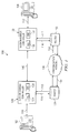
- FIGURE 1 is a simplified block diagram of communications system 100 for optimizing communications from network endpoints to various elements within a communication network environment.
- Communications system 100 may include a number of IP session terminal devices or interfaces (102, 106) and a set of communication links 110, 112. Interfaces (102, 106) are preferably positioned as endpoints of communications system 100.
- Communications system 100 may also include a pair of session border controllers 120, 122, which control the signaling and the data streams involved in a call session.
- Communications system 100 may also include a pair of routers (124, 126), wherein at least one router is coupled to each of the SBCs (120, 122) by sets of communication links 114, 115, 116, 117.
- SBCs 120, 122 may be configured to be hosted either as a part of routers 124, 126 (e.g., the service on a stick model) or may be externally coupled to routers 124, 126, such as by wired or wireless implementation.
- SBCs (120, 122) and routers (124, 126) may communicate using a well-known protocol technology via a physical interface or a logical interprocess communication mechanism.
- Communications system 100 provides the ability for interfaces (102, 106) to communicate via SBCs 120, 122 through communication network 130.
- Communication network 130 may be configured as a local or global communication network, such as the Internet or any other suitable communication network.
- SBCs 120, 122 are configured as application layer signaling devices, working in conjunction with routers 124, 126, such as MPLS PE routers, to control network traffic between endpoints.
- SBCs generally may be inserted into the signaling and media streams between the originating endpoint and the receiving endpoint so that the SBC may control the signaling traffic and the media traffic of the session.
- Interfaces (102, 106) each represent an end user, a client, or a customer wishing to initiate communication or participate in a call session via communications system 100.
- Interfaces (102, 106) may be inclusive of devices used to initiate or participate in the call session, such as a telephone, a video phone system, a computer, a handheld or mobile device, a laptop computer, a personal computer (PC)-based video phone, a streaming client, an SIP-enabled telephone of any kind, or any other device, component, element, or object capable of initiating voice, video, or data exchanges within communications system 100.
- Interfaces (102, 106) may also be inclusive of a suitable interface to the human user, such as a microphone, a display, a keyboard, a whiteboard, a video-conferencing interface or bridge, or other terminal equipment.
- Interfaces (102, 106) may also be any device that seeks to initiate or participate in the call session on behalf of another entity or element, such as another end user, a program, a database, an application, a piece of software, or any other component, device, element, or object capable of initiating a voice, a video, or a data exchange within communications system 100.
- Data refers to any type of alphanumeric, voice/audio, video, audio-visual, or script data, any type of source or object code, or any other suitable information in any appropriate format that may be communicated from one interface to another.
- interfaces (102, 106) may also be any device that seeks to initiate or participate in the call session on behalf of another entity or element.
- interfaces (102, 106) may be configured to include an output display, one or more knobs, pushbuttons, tactile user inputs, which facilitate controlling various interface functions.
- Interfaces (102, 106) may be configured to display data related to establishing, conducting, and terminating a call session within a communication network.
- the output display of interfaces (102, 106) may be a touch screen display, while in other exemplary embodiments, may be any other display technology type (e.g., LCD, DLP, plasma, CRT) or configuration.
- the knobs, pushbuttons, or tactile user inputs may be configured to establish of manage a call session.
- interfaces (102, 106), session border controllers (120, 122), and routers (124, 126) may be configured to transmit and receive a data requests and/or electrical signals via a wired or wireless medium.
- interfaces (102, 106) may be configured to establish a call session via a wired communication link.
- interfaces (102, 106) may be configured to establish a wireless communication link such as via a wireless communications protocol, such as an IEEE 802.11 protocol, an IEEE 802.16 protocol, IEEE 802.20 protocol, a Bluetooth communications protocol, a mobile device signal, an RF signal, an infrared signal, or any other suitable wireless technology.
- a wireless communications protocol such as an IEEE 802.11 protocol, an IEEE 802.16 protocol, IEEE 802.20 protocol, a Bluetooth communications protocol, a mobile device signal, an RF signal, an infrared signal, or any other suitable wireless technology.
- Routers (124, 126) are configured to route data packets within communications system 100.
- routers (124, 126) may be configured as label edge routers (LER), which are configured to push a label on an incoming data packet and pop off a label of an outgoing data packet. Particularly, when transmitting data packets in communications system 100.
- routers (124, 126) use routing information to determine appropriate labels to be affixed and label the data packet accordingly to be tranmitted within the communication network. Also, upon receiving a labelled data packet that is addressed to exit the network, routers (124, 126) are configured to remove the appropriate label and forward the resulting data packet.
- LER label edge routers
- router (124, 126) may also include label switch routers (LSR), which are configured to switch the labels on the data packets, in order to perform the routing of the data packets based on the label associated with the data packet.
- LSRs are configured such that when an LSR receives a data packet, the LSR may use the label in the data packet header to determine the next hop on the path of the data packet and a corresponding label for the data packet from a look-up table. The previous label is then removed from the header and replaced with a new label before the packet is routed forward in the data path.
- Communication links (110, 112) represent a set of local communication networks (i.e., a local area network within a corporation) in one embodiment.
- Communication links (110, 112) may serve one or more individuals and, further, offer connectivity to any number of devices in the call session (e.g. telephones, video conference systems, handheld or mobile devices, desktop and laptop computers, etc.).
- Communication links (110, 112) are configured to be coupled to SBCs 120, 122 of communications system 100.
- communication links (110, 112) may be configured as virtual private networks (VPNs), wireless LANs (WLANs), metropolitan area networks (MANs), wide area networks (WANs), or any other suitable architecture that offers connectivity to a group of end users.
- VPNs virtual private networks
- WLANs wireless LANs
- MANs metropolitan area networks
- WANs wide area networks
- SBCs 120 and 122 are configured to facilitate communications via communication links (110, 112) and control interfaces (114, 115, 116. 117).
- SBCs are control devices used to control the signaling and the data streams involved in establishing, conducting, and terminating a call session within a communication network.
- each SBC may be configured to include a signaling path border element (SBE) (130, 134) and a data path border element (DBE) (132, 136).
- SBE signaling path border element
- DBE data path border element
- the configuration of the SBC may be reflective of accommodations being made for a particular type of communications protocol or plan, a distributed architecture, or based on selected performance or service parameters.
- SBCs 120, 122 may be configured to facilitate network communication with a segmented QoS resource reservation type known as a middle segment resource reservation.
- the middle segment resource reservation type assist in avoiding an overload of the endpoint-to-endpoint or "e2e" resource reservation type.
- the middle segment reservation type indicates that the reservation may be installed on a segment of a communication network that is under the scope of control of two corresponding application layer devices, such as two corresponding SBCs that are involved in a protocol dialog.
- an endpoint-to-endpoint resource reservation type indicates that the reservation spans the entire network between two end-systems.
- 'I'lic middle segment reservation type provides the capability to require a reservation on some specific subset of the network that is not a local or endpoint-to-endpoint connection.
- Control interfaces (114, 115, 116, 117) arc configured to be coupled to session border controllers (120, 122) and routers (124, 126).
- Control Interfaces (114, 115, 116, 117) are configured for session border controllers (120, 122) to exert control over certain features of routers (124, 126).
- control interfaces (114, 115, 116, 117) may be configured to create, dimension, manage, and terminate session tunnels (152, 154), such as MPLS TE tunnels, between session border controllers (120, 122) and routers (124, 126).
- the creation, dimensioning, management, and termination of the session tunnels is performed based on events or conditions which are discerned by session border controllers (120, 122).
- Signaling interface (140) is configured to be coupled between SBCs (120, 122), therefore allowing the SBCs to exchange application layer signaling.
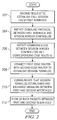
- FIGURE 2 illustrates a general example method of dynamically establishing a session tunnel.
- a session border controller receives a request from a first interface to establish a call session.
- a signaling protocol dialog such as Session Initiation Protocol (SIP)
- SIP Session Initiation Protocol
- the middle-segment QoS is signaled between SBCs 120 and 122.
- the SBCs are configured to initiate communication with its corresponding edge router (step 206) via control interface 115, which is coupled to the SBC.
- the SBC is configured to include a set of stored application layer routing policies, such as access and interpret routing policies, for establishing a session tunnel on behalf of the interface (i.e., telephone, video phone, mobile device, etc.).
- the routing policies which are accessible by the SBC, determine the communication resource requirements between the SBC and the first edge router and also communications across the middle segment (i.e., between the first edge router and the second edge router).
- the routing policies provision the SBC to determine the necessity of dynamically establishing a session tunnel on behalf of the interfaces positioned at the endpoints of the network.
- the middle segment resource reservation type assist in avoiding unduly overloading the semantics of the end-to-end QoS semantics by limiting the reservation to a specific subset of the network, the middle segment.
- the first edge router is connected with a second edge router in order to establish at least one session tunnel 152 (shown in FIGURE 1 ), wherein the second edge router is positioned proximate to at least a second interface.
- the second interface may be configured to connect with the first interface via a second SBC and a router, as shown in FIGURE 1 .
- session tunnel 152 is unidirectional and the application session is bi-directional
- uni-directional session tunnel 154 is established from the second edge router.
- the routers communicate that the session tunnel(s) were dynamically established and exchange signaling over the communication network.
- data packets flow between the first and second interface via SBCs and routers over the session tunnel(s) of the communication network.
- the dimensions of the session tunnel(s) may be specified based on the request of the first interface.
- the session tunnel(s) may be configured to be dynamically dimensioned with the desired bandwidth and other performance requirements, as needed during the call session. Further, the session tunnel(s) may be configured to be dynamically terminated upon release of the resources by the first and at least second interfaces.
- the SBC is configured to exert granular and deterministic control over the media transmitted over the session tunnel, thereby enabling a secure, deterministic, and manageable high-bandwidth call session tunnel.
- the signaling protocol dialog may be a protocol such as Real-Time Streaming Protocol (RTSP).
- RTSP may be used to support a streaming video implementation. Routing policies and support for the signaling protocol may be updated at the level or the SBC; however, the method for establishing the session tunnel may be similar to an embodiment using SIP protocol.
- Session Description Protocol is a format generally used for characterizing streaming media initialization parameters.
- SDP is typically used by application layer signaling protocols (of interfaces 102, 106 and SBCs 120, 122) to provide details about the media being conveyed during a call session and in order to establish the Quality of Service (QoS) pre-conditions which must be satisfied for the media to be successfully transmitted.
- QoS Quality of Service
- SBCs 120, 122
- Communications system 100 is configured to use SDP to indicate that a session tunnel is required between two endpoints and to convey the necessary information to establish the session tunnel.
- Multiple application layer signaling protocols may inherit the functionality of SDP to convey the necessary media parameters for the session tunnel.
- these application layer signaling protocols may include SIP and RTSP.
- SDP may be transported within the message body of the SIP signaling message.
- SDP message body with QoS pre-conditions, may include the following:
- a conventional SDP message body may not include the necessary parameters to establish and dimension a pair of uni-directional session tunnels, such as MPLS-TE tunnels. Therefore, communications system 100 is configured to include the SDP attributes in the message body for establishing the MPLS tunnel and for conveying the necessary media parameters for dimensioning the tunnel. Particularly, one embodiment of a message body may be configured to include one or more of the following SDP attributes for establishing and dimensioning an MPLS tunnel:
- Communications system 100 may be configured to include the SDP attributes and the SDP status-type parameter indicative of communicating over the middle segment resource reservation type.
- the value for the SDP status-type parameter may be denoted as "middle_ segment”.
- the "middle_segment" status-type parameter is configured to indicate that the reservation type is to be applicable to a network segment under the scope of control of two corresponding application layer devices involved in a protocol dialog.
- an SDP message body with the new parameters, may include the following:
- the present innovation contemplates methods, systems and program products on any machine readable media for accomplishing its operations.
- the embodiments of the present innovation may be implemented using an existing computer processor, or by a special purpose computer processor for an appropriate system, incorporated for this or another purpose or by a hardwired system.
- embodiments within the scope of the present innovation include program products comprising machine-readable media for carrying or having machine-executable instructions or data structures stored thereon.
- machine readable media an be any available media which can be accessed by a general purpose or special purpose computer or other machine with a processor.
Landscapes
- Engineering & Computer Science (AREA)
- Computer Networks & Wireless Communication (AREA)
- Signal Processing (AREA)
- Data Exchanges In Wide-Area Networks (AREA)
Claims (15)
- Verfahren, das Folgendes umfasst:Empfangen einer Anfrage von einer ersten Schnittstelle (102) zur Herstellung einer Sitzung mit mindestens einer zweiten Schnittstelle (106) in einem Kommunikationsnetzwerk, wobei die Anfrage an eine Anwendungsschicht-Signalisierungsvorrichtung (120) über einen Anwendungsschicht-Signalisierungsprotokolldialog übertragen wird, wobei der Anwendungsschicht-Signalisierungsprotokolldialog dafür konfiguriert ist, die Kommunikation zwischen der ersten Schnittstelle (102) und der Anwendungsschicht-Signalisierungsvorrichtung (120) zu ermöglichen; undKommunizieren von Parametern zur Einrichtung eines Sitzungstunnels zu einem ersten Edge-Router (124) über den Anwendungsschicht-Signalisierungsprotokolldialog, wobei der erste Edge-Router (124) in der Lage ist, den Sitzungstunnel zwischen dem ersten Edge-Router (124) und mindestens einem zweiten Edge-Router (126) basierend auf den übermittelten Parametern dynamisch einzurichten, wobei der Sitzungstunnel die Kommunikation zwischen der ersten und zweiten Schnittstelle (102 und 106) über den ersten und zweiten Edge-Router (124 und 126) ermöglicht.
- Verfahren nach Anspruch 1, das ferner den Schritt des Identifizierens des mindestens zweiten Edge-Routers (126) in dem Kommunikationsnetzwerk umfasst, um die Einrichtung des Sitzungstunnels mit dem ersten Edge-Router (124) zu ermöglichen.
- Verfahren nach Anspruch 1, das ferner den Schritt des Beendens des Sitzungstunnels nach Abschluss der Sitzung umfasst.
- Verfahren nach Anspruch 1, wobei die Parameter des Sitzungstunnels basierend auf der Anfrage bestimmt werden, die die Anwendungsschicht-Signalisierungsvorrichtung (120) von der ersten Schnittstelle (102) empfängt.
- Verfahren nach Anspruch 1, wobei die Parameter Folgendes umfassen: Tunnelbandbreite und Zeitdauer der Sitzung.
- Verfahren nach Anspruch 1, wobei die Parameter Folgendes umfassen:Quelle des lokalen Tunnels, Ziel des lokalen Tunnels, Tunnelidentifizierung, Spezifikation des Vorwärtsfilters oder Spezifikation des Rückwärtsfilters.
- Verfahren nach Anspruch 1, wobei der Sitzungstunnel zur Unterstützung mindestens eines Paars von unidirektionalen Sitzungstunnels bereitgestellt wird, um eine Kommunikation in Vorwärts- und Rückwärtsrichtung zwischen dem ersten und zweiten Edge-Router (124 und 126) zu ermöglichen.
- Verfahren nach Anspruch 1, wobei das Signalisierungsprotokoll ein Sitzungsinitierungsprotokoll oder ein Echtzeit-Streaming- Protokoll umfasst.
- Verfahren nach Anspruch 1, wobei die Sitzung einen Videokonferenzanruf umfasst.
- System, das Folgendes umfasst:ein Mittel zum Empfangen einer Anfrage von einer ersten Schnittstelle (102) zur Herstellung einer Sitzung mit mindestens einer zweiten Schnittstelle (106) in einem Kommunikationsnetzwerk, wobei die Anfrage an eine Anwendungsschicht-Signalisierungsvorrichtung (120) über einen Anwendungsschicht-Signalisierungsprotokolldialog übertragen wird, wobei der Anwendungsschicht-Signalisierungsprotokolldialog dafür konfiguriert ist, die Kommunikation zwischen der ersten Schnittstelle und der Anwendungsschicht-Signalisierungsvorrichtung zu ermöglichen; undein Mittel zum Kommunizieren von Parametern zur Einrichtung eines Sitzungstunnels zu einem ersten Edge-Router (124) über den Anwendungsschicht-Signalisierungsprotokolldialog, wobei der erste Edge-Router (124) in der Lage ist, den Sitzungstunnel zwischen dem ersten Edge-Router (124) und mindestens einem zweiten Edge-Router (126) basierend auf den übermittelten Parametern dynamisch einzurichten, wobei der Tunnel die Kommunikation zwischen der ersten und zweiten Schnittstelle (102 und 104) über den ersten und zweiten Edge-Router (124) ermöglicht.
- System nach Anspruch 10, das dafür ausgelegt ist, ein Verfahren nach einem der Ansprüche 1 bis 9 durchzuführen.
- System nach Anspruch 10, das von einer Anwendungsschicht-Signalisierungsvorrichtung (120) bereitgestellt wird, die dafür konfiguriert ist, ein Verfahren nach einem der Ansprüche 1 bis 9 durchzuführen.
- System nach Anspruch 12, wobei der Anwendungsschicht-Signalisierungsprotokolldialog dafür konfiguriert ist, eine Internetprotokolladresse (IP-Adresse) der Schnittstelle (102) bereitzustellen, um Datenverkehr in dem Sitzungstunnel zu verwalten.
- System nach Anspruch 12, wobei der Anwendungsschicht-Signalisierungsprotokolldialog dafür konfiguriert ist, einen Tunnelidentifizierungsparameter bereitzustellen, der die Vorwärtsrichtung des Sitzungstunnels angibt.
- System nach Anspruch 12, wobei der Sitzungstunnel einen Mehrprotokoll-Etikettenumschalttunnel (Multiprotocol Label Switching-Tunnel) umfasst.
Applications Claiming Priority (2)
| Application Number | Priority Date | Filing Date | Title |
|---|---|---|---|
| US12/138,908 US8493984B2 (en) | 2008-06-13 | 2008-06-13 | System and method for establishment of a multiprotocol label switching (MPLS) tunnel |
| PCT/US2009/046672 WO2009152116A1 (en) | 2008-06-13 | 2009-06-09 | System and method for establishment of a multiprotocol label switching (mpls) tunnel |
Publications (3)
| Publication Number | Publication Date |
|---|---|
| EP2286549A1 EP2286549A1 (de) | 2011-02-23 |
| EP2286549A4 EP2286549A4 (de) | 2011-05-18 |
| EP2286549B1 true EP2286549B1 (de) | 2016-08-10 |
Family
ID=41414731
Family Applications (1)
| Application Number | Title | Priority Date | Filing Date |
|---|---|---|---|
| EP09763407.5A Active EP2286549B1 (de) | 2008-06-13 | 2009-06-09 | System und verfahren zur herstellung eines mpls-tunnels (multiprotocol label switching) |
Country Status (4)
| Country | Link |
|---|---|
| US (1) | US8493984B2 (de) |
| EP (1) | EP2286549B1 (de) |
| CN (1) | CN102057630B (de) |
| WO (1) | WO2009152116A1 (de) |
Families Citing this family (4)
| Publication number | Priority date | Publication date | Assignee | Title |
|---|---|---|---|---|
| US10158680B2 (en) * | 2016-01-20 | 2018-12-18 | Oracle International Corporation | Co-transported tunnels for encapsulated traffic |
| FR3049140A1 (fr) * | 2016-03-15 | 2017-09-22 | Orange | Procede de gestion dynamique de chemins de communication entre routeurs en fonction de besoins applicatifs |
| CN110545241B (zh) * | 2018-05-28 | 2022-05-17 | 华为技术有限公司 | 一种报文处理方法和装置 |
| US11477112B2 (en) * | 2021-03-09 | 2022-10-18 | Cisco Technology, Inc. | On-the-fly SD-WAN tunnel creation for application-driven routing |
Citations (2)
| Publication number | Priority date | Publication date | Assignee | Title |
|---|---|---|---|---|
| US20030118028A1 (en) * | 2002-02-27 | 2003-06-26 | Neal Warren Michael | Method and system of ensuring quality of service between networks using a signaling protocol |
| US20070213060A1 (en) * | 2006-03-07 | 2007-09-13 | Interdigital Technology Corporation | Method and apparatus for supporting handoff in an lte gtp based wireless communication system |
Family Cites Families (35)
| Publication number | Priority date | Publication date | Assignee | Title |
|---|---|---|---|---|
| US5852601A (en) * | 1991-09-09 | 1998-12-22 | Network Equipment Technologies, Inc. | Method and apparatus for reactive congestion control in an asynchronous transfer mode (ATM) network |
| US6408001B1 (en) * | 1998-10-21 | 2002-06-18 | Lucent Technologies Inc. | Method for determining label assignments for a router |
| GB9905509D0 (en) * | 1999-03-10 | 1999-05-05 | Northern Telecom Ltd | Label switched media gateway and network |
| US6678264B1 (en) * | 1999-06-30 | 2004-01-13 | Nortel Networks Limited | Establishing connections with a pre-specified quality of service across a communication network |
| US7315510B1 (en) * | 1999-10-21 | 2008-01-01 | Tellabs Operations, Inc. | Method and apparatus for detecting MPLS network failures |
| JP4031894B2 (ja) * | 1999-10-29 | 2008-01-09 | 富士通株式会社 | Mpls通信方式における通信データ確認試験方法及びその方法を利用するルータ,交換機,通信システム |
| US6714987B1 (en) * | 1999-11-05 | 2004-03-30 | Nortel Networks Limited | Architecture for an IP centric distributed network |
| US6665273B1 (en) * | 2000-01-11 | 2003-12-16 | Cisco Technology, Inc. | Dynamically adjusting multiprotocol label switching (MPLS) traffic engineering tunnel bandwidth |
| US6980526B2 (en) | 2000-03-24 | 2005-12-27 | Margalla Communications, Inc. | Multiple subscriber videoconferencing system |
| JP4168574B2 (ja) * | 2000-06-02 | 2008-10-22 | 株式会社日立製作所 | パケット転送装置、パケット転送制御方法、及びパケット転送装置の設定方法 |
| US6477166B1 (en) * | 2000-06-30 | 2002-11-05 | Marconi Communications, Inc. | System, method and switch for an MPLS network and an ATM network |
| US7088720B1 (en) * | 2000-08-07 | 2006-08-08 | Sbc Technology Resources, Inc. | Multiservice use of network connection capability under user-to-network interface signaling |
| JP3654168B2 (ja) * | 2000-09-28 | 2005-06-02 | 日本電気株式会社 | インタフェース識別装置、インタフェース識別方法および、mpls−vpnサービスネットワーク |
| US20020126201A1 (en) * | 2001-03-08 | 2002-09-12 | Star-Bak Communication Inc. | Systems and methods for connecting video conferencing to a distributed network |
| US20020181462A1 (en) * | 2001-04-24 | 2002-12-05 | Sorin Surdila | System and method for providing end-to-end quality of service (QoS) across multiple internet protocol (IP) networks |
| EP1388078A1 (de) * | 2001-05-03 | 2004-02-11 | Nokia Inc. | Verfahren und system zur implementierung von mpls-redundanz |
| WO2002104046A1 (en) * | 2001-06-15 | 2002-12-27 | Nokia Corporation | Mapping of packets to pdp contexts in multisession connection |
| US6856991B1 (en) * | 2002-03-19 | 2005-02-15 | Cisco Technology, Inc. | Method and apparatus for routing data to a load balanced server using MPLS packet labels |
| AU2003256590A1 (en) * | 2002-07-16 | 2004-02-02 | Enterasys Networks, Inc. | Apparatus and method for a virtual hierarchial local area network |
| US7257119B2 (en) | 2002-12-23 | 2007-08-14 | At&T | MPLS virtual private network using dual network cores |
| CN100477628C (zh) * | 2003-05-16 | 2009-04-08 | 富士通株式会社 | 通过多层进行通信的通信网中的路径设定方法和通信装置 |
| US6925081B2 (en) * | 2003-07-11 | 2005-08-02 | Cisco Technology, Inc. | MPLS device enabling service providers to control service levels in forwarding of multi-labeled packets |
| US20050041808A1 (en) * | 2003-08-22 | 2005-02-24 | Nortel Networks Limited | Method and apparatus for facilitating roaming between wireless domains |
| CN1898917B (zh) | 2003-12-22 | 2011-06-08 | 艾利森电话股份有限公司 | 移动分组流的控制 |
| CN100505746C (zh) * | 2004-02-07 | 2009-06-24 | 华为技术有限公司 | 实现虚拟租用线的方法 |
| US7564802B2 (en) * | 2005-03-25 | 2009-07-21 | Alcatel-Lucent Usa Inc. | Method for optimal assignment of customer edge (CE) routers to virtual private network route forwarding (VRF) tables |
| US7983254B2 (en) * | 2005-07-20 | 2011-07-19 | Verizon Business Global Llc | Method and system for securing real-time media streams in support of interdomain traversal |
| CN1905517A (zh) | 2005-07-30 | 2007-01-31 | 华为技术有限公司 | 在ngn网络中为媒体流选择转发路径的控制系统及方法 |
| US20070150946A1 (en) * | 2005-12-23 | 2007-06-28 | Nortel Networks Limited | Method and apparatus for providing remote access to an enterprise network |
| US8914868B2 (en) * | 2006-03-03 | 2014-12-16 | Hewlett-Packard Development Company, L.P. | Vendor-neutral policy based mechanism for enabling firewall service in an MPLS-VPN service network |
| US7660299B2 (en) | 2006-05-05 | 2010-02-09 | Cisco Technology, Inc. | Network-based call interface device for real-time packet protocol calls |
| WO2007137765A1 (en) | 2006-05-29 | 2007-12-06 | Panasonic Corporation | Method and apparatus for simultaneous location privacy and route optimization for communication sessions |
| US7649881B2 (en) * | 2006-12-14 | 2010-01-19 | Nortel Networks Limited | Pinning the route of IP bearer flows in a next generation network |
| US7936695B2 (en) * | 2007-05-14 | 2011-05-03 | Cisco Technology, Inc. | Tunneling reports for real-time internet protocol media streams |
| JP4789864B2 (ja) * | 2007-05-31 | 2011-10-12 | 株式会社日立製作所 | ルータ装置 |
-
2008
- 2008-06-13 US US12/138,908 patent/US8493984B2/en not_active Expired - Fee Related
-
2009
- 2009-06-09 CN CN2009801219117A patent/CN102057630B/zh active Active
- 2009-06-09 WO PCT/US2009/046672 patent/WO2009152116A1/en not_active Ceased
- 2009-06-09 EP EP09763407.5A patent/EP2286549B1/de active Active
Patent Citations (2)
| Publication number | Priority date | Publication date | Assignee | Title |
|---|---|---|---|---|
| US20030118028A1 (en) * | 2002-02-27 | 2003-06-26 | Neal Warren Michael | Method and system of ensuring quality of service between networks using a signaling protocol |
| US20070213060A1 (en) * | 2006-03-07 | 2007-09-13 | Interdigital Technology Corporation | Method and apparatus for supporting handoff in an lte gtp based wireless communication system |
Also Published As
| Publication number | Publication date |
|---|---|
| CN102057630A (zh) | 2011-05-11 |
| CN102057630B (zh) | 2013-12-04 |
| EP2286549A4 (de) | 2011-05-18 |
| EP2286549A1 (de) | 2011-02-23 |
| US8493984B2 (en) | 2013-07-23 |
| US20090310614A1 (en) | 2009-12-17 |
| WO2009152116A1 (en) | 2009-12-17 |
Similar Documents
| Publication | Publication Date | Title |
|---|---|---|
| EP3641242B1 (de) | Verfahren und netzwerkvorrichtung zur errichtung eines flexiblen ethernet-pfads | |
| JP4033773B2 (ja) | ネットワークルーティングを実行する方法および装置 | |
| US9692710B2 (en) | Media stream management | |
| US7502320B2 (en) | Method and apparatus for network-based admission control using path-coupled quality of service signaling | |
| CN105991856B (zh) | 基于rtp服务器到服务器寻路由的voip寻路由 | |
| AU6968800A (en) | An architecture for an IP centric distributed network | |
| US9729379B2 (en) | Method and network equipment for maintaining a media stream through another network equipment while suspending an associated media stream connection in a communication network | |
| WO2009143722A1 (zh) | 实现区分服务流量工程的方法及设备 | |
| US20070074283A1 (en) | Method and apparatus for activating alternative virtual private network protocols | |
| US8493984B2 (en) | System and method for establishment of a multiprotocol label switching (MPLS) tunnel | |
| JP7673158B2 (ja) | レジデンシャルゲートウェイへのネットワークアクセスのための装置、方法、および非一時的コンピュータ可読記憶媒体 | |
| US8121028B1 (en) | Quality of service provisioning for packet service sessions in communication networks | |
| CN101483647A (zh) | 一种协议版本号协商方法及网络实体装置 | |
| CN100559755C (zh) | 自动发现虚拟网络的方法和系统 | |
| US8451725B1 (en) | Method and apparatus for distributed compositional control of end-to-end media in IP networks | |
| US9191518B2 (en) | Routing system for transferring data packets of a call | |
| US11848861B2 (en) | Multiprotocol label switching (MPLS) traffic engineering design for IP multimedia subsystem-based voice over Internet protocol | |
| US11509574B2 (en) | Multiprotocol label switching (MPLS) traffic engineering design for IP multimedia subsystem-based voice over internet protocol | |
| JP7720436B2 (ja) | ネットワークアクセスのための装置、方法、および非一時的コンピュータ可読記憶媒体 | |
| Simon et al. | Resource Reservation in DetNet with AVB | |
| Kim et al. | Session and connection management for QoS-guaranteed multimedia service provisioning on IP/MPLS networks | |
| Mohameda et al. | RSVP BASED MPLS VERSUS IP PERFORMANCE EVALUATION | |
| Zhang et al. | A Framework for Traffic Engineering In a SIP-over-MPLS based network | |
| Ikeda et al. | Context-aware quality of service control in session based IP networks | |
| Behl | CCIE Collaboration Quick Reference |
Legal Events
| Date | Code | Title | Description |
|---|---|---|---|
| PUAI | Public reference made under article 153(3) epc to a published international application that has entered the european phase |
Free format text: ORIGINAL CODE: 0009012 |
|
| 17P | Request for examination filed |
Effective date: 20101222 |
|
| AK | Designated contracting states |
Kind code of ref document: A1 Designated state(s): AT BE BG CH CY CZ DE DK EE ES FI FR GB GR HR HU IE IS IT LI LT LU LV MC MK MT NL NO PL PT RO SE SI SK TR |
|
| AX | Request for extension of the european patent |
Extension state: AL BA RS |
|
| A4 | Supplementary search report drawn up and despatched |
Effective date: 20110415 |
|
| RIC1 | Information provided on ipc code assigned before grant |
Ipc: H04L 12/56 20060101ALI20110411BHEP Ipc: H04L 12/28 20060101AFI20100107BHEP |
|
| DAX | Request for extension of the european patent (deleted) | ||
| 17Q | First examination report despatched |
Effective date: 20120904 |
|
| REG | Reference to a national code |
Ref country code: DE Ref legal event code: R079 Ref document number: 602009040268 Country of ref document: DE Free format text: PREVIOUS MAIN CLASS: H04L0012280000 Ipc: H04L0012801000 |
|
| GRAP | Despatch of communication of intention to grant a patent |
Free format text: ORIGINAL CODE: EPIDOSNIGR1 |
|
| RIC1 | Information provided on ipc code assigned before grant |
Ipc: H04L 12/801 20130101AFI20151216BHEP |
|
| INTG | Intention to grant announced |
Effective date: 20160107 |
|
| GRAS | Grant fee paid |
Free format text: ORIGINAL CODE: EPIDOSNIGR3 |
|
| GRAA | (expected) grant |
Free format text: ORIGINAL CODE: 0009210 |
|
| AK | Designated contracting states |
Kind code of ref document: B1 Designated state(s): AT BE BG CH CY CZ DE DK EE ES FI FR GB GR HR HU IE IS IT LI LT LU LV MC MK MT NL NO PL PT RO SE SI SK TR |
|
| REG | Reference to a national code |
Ref country code: GB Ref legal event code: FG4D |
|
| REG | Reference to a national code |
Ref country code: CH Ref legal event code: EP Ref country code: AT Ref legal event code: REF Ref document number: 819923 Country of ref document: AT Kind code of ref document: T Effective date: 20160815 |
|
| REG | Reference to a national code |
Ref country code: IE Ref legal event code: FG4D |
|
| REG | Reference to a national code |
Ref country code: DE Ref legal event code: R096 Ref document number: 602009040268 Country of ref document: DE |
|
| REG | Reference to a national code |
Ref country code: LT Ref legal event code: MG4D |
|
| REG | Reference to a national code |
Ref country code: NL Ref legal event code: MP Effective date: 20160810 |
|
| REG | Reference to a national code |
Ref country code: AT Ref legal event code: MK05 Ref document number: 819923 Country of ref document: AT Kind code of ref document: T Effective date: 20160810 |
|
| PG25 | Lapsed in a contracting state [announced via postgrant information from national office to epo] |
Ref country code: NO Free format text: LAPSE BECAUSE OF FAILURE TO SUBMIT A TRANSLATION OF THE DESCRIPTION OR TO PAY THE FEE WITHIN THE PRESCRIBED TIME-LIMIT Effective date: 20161110 Ref country code: LT Free format text: LAPSE BECAUSE OF FAILURE TO SUBMIT A TRANSLATION OF THE DESCRIPTION OR TO PAY THE FEE WITHIN THE PRESCRIBED TIME-LIMIT Effective date: 20160810 Ref country code: HR Free format text: LAPSE BECAUSE OF FAILURE TO SUBMIT A TRANSLATION OF THE DESCRIPTION OR TO PAY THE FEE WITHIN THE PRESCRIBED TIME-LIMIT Effective date: 20160810 Ref country code: IT Free format text: LAPSE BECAUSE OF FAILURE TO SUBMIT A TRANSLATION OF THE DESCRIPTION OR TO PAY THE FEE WITHIN THE PRESCRIBED TIME-LIMIT Effective date: 20160810 Ref country code: NL Free format text: LAPSE BECAUSE OF FAILURE TO SUBMIT A TRANSLATION OF THE DESCRIPTION OR TO PAY THE FEE WITHIN THE PRESCRIBED TIME-LIMIT Effective date: 20160810 Ref country code: IS Free format text: LAPSE BECAUSE OF FAILURE TO SUBMIT A TRANSLATION OF THE DESCRIPTION OR TO PAY THE FEE WITHIN THE PRESCRIBED TIME-LIMIT Effective date: 20161210 Ref country code: FI Free format text: LAPSE BECAUSE OF FAILURE TO SUBMIT A TRANSLATION OF THE DESCRIPTION OR TO PAY THE FEE WITHIN THE PRESCRIBED TIME-LIMIT Effective date: 20160810 |
|
| PG25 | Lapsed in a contracting state [announced via postgrant information from national office to epo] |
Ref country code: PL Free format text: LAPSE BECAUSE OF FAILURE TO SUBMIT A TRANSLATION OF THE DESCRIPTION OR TO PAY THE FEE WITHIN THE PRESCRIBED TIME-LIMIT Effective date: 20160810 Ref country code: AT Free format text: LAPSE BECAUSE OF FAILURE TO SUBMIT A TRANSLATION OF THE DESCRIPTION OR TO PAY THE FEE WITHIN THE PRESCRIBED TIME-LIMIT Effective date: 20160810 Ref country code: GR Free format text: LAPSE BECAUSE OF FAILURE TO SUBMIT A TRANSLATION OF THE DESCRIPTION OR TO PAY THE FEE WITHIN THE PRESCRIBED TIME-LIMIT Effective date: 20161111 Ref country code: PT Free format text: LAPSE BECAUSE OF FAILURE TO SUBMIT A TRANSLATION OF THE DESCRIPTION OR TO PAY THE FEE WITHIN THE PRESCRIBED TIME-LIMIT Effective date: 20161212 Ref country code: LV Free format text: LAPSE BECAUSE OF FAILURE TO SUBMIT A TRANSLATION OF THE DESCRIPTION OR TO PAY THE FEE WITHIN THE PRESCRIBED TIME-LIMIT Effective date: 20160810 Ref country code: SE Free format text: LAPSE BECAUSE OF FAILURE TO SUBMIT A TRANSLATION OF THE DESCRIPTION OR TO PAY THE FEE WITHIN THE PRESCRIBED TIME-LIMIT Effective date: 20160810 Ref country code: ES Free format text: LAPSE BECAUSE OF FAILURE TO SUBMIT A TRANSLATION OF THE DESCRIPTION OR TO PAY THE FEE WITHIN THE PRESCRIBED TIME-LIMIT Effective date: 20160810 |
|
| PG25 | Lapsed in a contracting state [announced via postgrant information from national office to epo] |
Ref country code: EE Free format text: LAPSE BECAUSE OF FAILURE TO SUBMIT A TRANSLATION OF THE DESCRIPTION OR TO PAY THE FEE WITHIN THE PRESCRIBED TIME-LIMIT Effective date: 20160810 Ref country code: RO Free format text: LAPSE BECAUSE OF FAILURE TO SUBMIT A TRANSLATION OF THE DESCRIPTION OR TO PAY THE FEE WITHIN THE PRESCRIBED TIME-LIMIT Effective date: 20160810 |
|
| REG | Reference to a national code |
Ref country code: DE Ref legal event code: R097 Ref document number: 602009040268 Country of ref document: DE |
|
| PG25 | Lapsed in a contracting state [announced via postgrant information from national office to epo] |
Ref country code: SK Free format text: LAPSE BECAUSE OF FAILURE TO SUBMIT A TRANSLATION OF THE DESCRIPTION OR TO PAY THE FEE WITHIN THE PRESCRIBED TIME-LIMIT Effective date: 20160810 Ref country code: BG Free format text: LAPSE BECAUSE OF FAILURE TO SUBMIT A TRANSLATION OF THE DESCRIPTION OR TO PAY THE FEE WITHIN THE PRESCRIBED TIME-LIMIT Effective date: 20161110 Ref country code: BE Free format text: LAPSE BECAUSE OF FAILURE TO SUBMIT A TRANSLATION OF THE DESCRIPTION OR TO PAY THE FEE WITHIN THE PRESCRIBED TIME-LIMIT Effective date: 20160810 Ref country code: CZ Free format text: LAPSE BECAUSE OF FAILURE TO SUBMIT A TRANSLATION OF THE DESCRIPTION OR TO PAY THE FEE WITHIN THE PRESCRIBED TIME-LIMIT Effective date: 20160810 Ref country code: DK Free format text: LAPSE BECAUSE OF FAILURE TO SUBMIT A TRANSLATION OF THE DESCRIPTION OR TO PAY THE FEE WITHIN THE PRESCRIBED TIME-LIMIT Effective date: 20160810 |
|
| PLBE | No opposition filed within time limit |
Free format text: ORIGINAL CODE: 0009261 |
|
| STAA | Information on the status of an ep patent application or granted ep patent |
Free format text: STATUS: NO OPPOSITION FILED WITHIN TIME LIMIT |
|
| REG | Reference to a national code |
Ref country code: FR Ref legal event code: PLFP Year of fee payment: 9 |
|
| 26N | No opposition filed |
Effective date: 20170511 |
|
| PG25 | Lapsed in a contracting state [announced via postgrant information from national office to epo] |
Ref country code: SI Free format text: LAPSE BECAUSE OF FAILURE TO SUBMIT A TRANSLATION OF THE DESCRIPTION OR TO PAY THE FEE WITHIN THE PRESCRIBED TIME-LIMIT Effective date: 20160810 |
|
| PG25 | Lapsed in a contracting state [announced via postgrant information from national office to epo] |
Ref country code: MC Free format text: LAPSE BECAUSE OF FAILURE TO SUBMIT A TRANSLATION OF THE DESCRIPTION OR TO PAY THE FEE WITHIN THE PRESCRIBED TIME-LIMIT Effective date: 20160810 |
|
| REG | Reference to a national code |
Ref country code: CH Ref legal event code: PL |
|
| REG | Reference to a national code |
Ref country code: IE Ref legal event code: MM4A |
|
| PG25 | Lapsed in a contracting state [announced via postgrant information from national office to epo] |
Ref country code: LU Free format text: LAPSE BECAUSE OF NON-PAYMENT OF DUE FEES Effective date: 20170609 Ref country code: CH Free format text: LAPSE BECAUSE OF NON-PAYMENT OF DUE FEES Effective date: 20170630 Ref country code: LI Free format text: LAPSE BECAUSE OF NON-PAYMENT OF DUE FEES Effective date: 20170630 Ref country code: IE Free format text: LAPSE BECAUSE OF NON-PAYMENT OF DUE FEES Effective date: 20170609 |
|
| REG | Reference to a national code |
Ref country code: FR Ref legal event code: PLFP Year of fee payment: 10 |
|
| PG25 | Lapsed in a contracting state [announced via postgrant information from national office to epo] |
Ref country code: MT Free format text: LAPSE BECAUSE OF NON-PAYMENT OF DUE FEES Effective date: 20170609 |
|
| PG25 | Lapsed in a contracting state [announced via postgrant information from national office to epo] |
Ref country code: HU Free format text: LAPSE BECAUSE OF FAILURE TO SUBMIT A TRANSLATION OF THE DESCRIPTION OR TO PAY THE FEE WITHIN THE PRESCRIBED TIME-LIMIT; INVALID AB INITIO Effective date: 20090609 |
|
| PG25 | Lapsed in a contracting state [announced via postgrant information from national office to epo] |
Ref country code: CY Free format text: LAPSE BECAUSE OF NON-PAYMENT OF DUE FEES Effective date: 20160810 |
|
| PG25 | Lapsed in a contracting state [announced via postgrant information from national office to epo] |
Ref country code: MK Free format text: LAPSE BECAUSE OF FAILURE TO SUBMIT A TRANSLATION OF THE DESCRIPTION OR TO PAY THE FEE WITHIN THE PRESCRIBED TIME-LIMIT Effective date: 20160810 |
|
| PG25 | Lapsed in a contracting state [announced via postgrant information from national office to epo] |
Ref country code: TR Free format text: LAPSE BECAUSE OF FAILURE TO SUBMIT A TRANSLATION OF THE DESCRIPTION OR TO PAY THE FEE WITHIN THE PRESCRIBED TIME-LIMIT Effective date: 20160810 |
|
| REG | Reference to a national code |
Ref country code: DE Ref legal event code: R079 Ref document number: 602009040268 Country of ref document: DE Free format text: PREVIOUS MAIN CLASS: H04L0012801000 Ipc: H04L0047100000 |
|
| P01 | Opt-out of the competence of the unified patent court (upc) registered |
Effective date: 20230525 |
|
| PGFP | Annual fee paid to national office [announced via postgrant information from national office to epo] |
Ref country code: DE Payment date: 20250519 Year of fee payment: 17 |
|
| PGFP | Annual fee paid to national office [announced via postgrant information from national office to epo] |
Ref country code: GB Payment date: 20250604 Year of fee payment: 17 |
|
| PGFP | Annual fee paid to national office [announced via postgrant information from national office to epo] |
Ref country code: FR Payment date: 20250613 Year of fee payment: 17 |