EP2286578B1 - Leistungs-backup-system - Google Patents
Leistungs-backup-system Download PDFInfo
- Publication number
- EP2286578B1 EP2286578B1 EP09746028.1A EP09746028A EP2286578B1 EP 2286578 B1 EP2286578 B1 EP 2286578B1 EP 09746028 A EP09746028 A EP 09746028A EP 2286578 B1 EP2286578 B1 EP 2286578B1
- Authority
- EP
- European Patent Office
- Prior art keywords
- power
- interface devices
- customer premise
- intermediate network
- network interface
- Prior art date
- Legal status (The legal status is an assumption and is not a legal conclusion. Google has not performed a legal analysis and makes no representation as to the accuracy of the status listed.)
- Active
Links
Images
Classifications
-
- H—ELECTRICITY
- H04—ELECTRIC COMMUNICATION TECHNIQUE
- H04M—TELEPHONIC COMMUNICATION
- H04M19/00—Current supply arrangements for telephone systems
- H04M19/08—Current supply arrangements for telephone systems with current supply sources at the substations
Definitions
- This invention relates to the provision of electrical power to elements of a telecommunications network.
- POTS public switched telephone network
- the end-to-end connection between a telephone exchange and customer premises is made by a branched network of wires along which an electric current can be transmitted, the current being modulated to provide analogue voice signals, and also digital pulses as used for dialling numbers, activating bells or other alerts ("ringing current") and, more recently, for data transmission such as facsimile transmissions or computer connections to the "Internet”.
- POTS plain old telephone system
- nodes intermediate elements
- Many of these points are either in public locations (the familiar roadside "cabinets", and the “distribution points” which are typically positioned at the top of wooden poles from where the "final drop” wire is connected to the customer premises).
- These nodes are unattended and often either in remote locations, where it may be difficult to arrange a mains power supply, or in public locations where the presence of a mains power supply could constitute a hazard to some members of the public, and a temptation to others.
- such nodes have had relatively modest power requirements, and provision of a low-voltage power supply from the exchange has been sufficient to avoid the need for a mains power supply to be provided to these nodes.
- node in this specification refers to elements within the network, as distinct from the “network termination point” (also known as the “network interface device” NID) located on a customer's premises which provides the interface between the network operator's equipment and that of the customer.
- network termination point also known as the “network interface device” NID
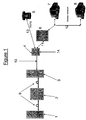
- FIG. 1 A typical arrangement is shown in Figure 1 .
- the exchange or central office 1 is connected by way of one or more intermediate nodes, known as cabinets 2 and distribution points 3, to the customer premises network termination equipment (NTE) 4.
- NTE customer premises network termination equipment
- the NTEs are connected to the distribution point 3, but longer connections where the termination is a long distance from any other termination may be connected directly to a cabinet 4 without an intermediate DP 3.
- Connected to the termination equipment 4 by internal connections 11, 13 are one or more standard telephones 5 and a "hub" (home gateway) 6 serving a home network 12 (wired or wireless) to which is connected one or more computer terminals 7, 8.
- the "final drop" 10 between the distribution point 3 and the customer premises network termination equipment 4 is made by copper connection, but the connections 9 between the central office 1 and the cabinet 2, and between the cabinet 2 and the distribution point 3, are made by fibre optic connection.
- Such arrangements break the hitherto continuous copper connection between the local exchange 1 and the customer premises 4, and more specifically between the local exchange 1 and the intermediate nodes (cabinet 2, distribution point 3).
- the intermediate nodes 2, 3 now have greater power requirements than hitherto, in particular because transmission over the optical or microwave links itself requires power to generate the optical or microwave carrier.
- a problem with such an arrangement is that the network provider is reliant on the customers' own electrical power supplies to power the service.
- the standard "POTS" services have to be powered by the customer supply 14.
- the customer In the event of failure of that supply, the customer would be deprived of telephone service. This is considered unacceptable, as it would prevent vulnerable users making calls in an emergency - in particular, calls to report the power failure itself.
- a method of supplying electrical power to elements of a telecommunications network comprising intermediate network nodes, at least some of said intermediate network nodes being configured to interconnect an optical connection and a plurality of wired electrical communications connections to respective customer premise network interface devices, wherein at least some of the customer premise network interface devices have an external power supply and are configured to supply electrical power to their respective intermediate network nodes over the wired electrical communications connections, the method comprising delivering electrical power over the wired electrical communications connections from an intermediate network node to customer premise network interface device currently having no other electrical power supply.
- the invention also provides an intermediate network node for a telecommunications network configured to interconnect an optical connection and two or more wired electrical communications connections to respective customer premise network interface devices, comprising a power management system arranged to allow the intermediate network node to receive electrical power from, and to deliver electrical power to, one or more of the customer premise network interface devices connected thereto by the wired electrical communications connection.
- a battery backup is preferably provided in the network node and is kept charged by a trickle charge from each participating user termination. This will allow a basic telephone service to be provided even during a widespread power outage.
- the parameters of this basic service may be set by the power management system of the node according to the remaining capacity of the battery, for example telephony-only, calls to/from specified numbers only, calls to the emergency services only (i.e. 112, 911, 999, according to country).
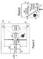
- Figure 3 depicts a network node 3 configured to interconnect an optical connection 9 and two or more wired local connections 10, 110. It includes an optical/copper interface 31 for converting signals from the optical connection 9 to baseband for transmission over the copper connections 10, 110, and vice versa. There is also a multiplexer/demultiplexer 32 for distributing the signals to the two or more wired connections 10, 110, and for combining the signals received therefrom.
- the optical/copper interface 31 and multiplexer/demultiplexer 32 require electrical power to operate, and this power is distributed to these components by a power distribution unit 36 in the network node 3.
- the power is supplied to the power distribution unit 36 from the customer equipment 4, 104 through the wired connections 10, 110.
- the network node 3 is provided with a power control module 33 which generates signals to control the co-operating equipments 4, 104 to deliver the power required, in accordance with demand assessed by the power distribution unit 36.
- the power control module 33 is programmed to generate power control signals in accordance with known properties of the various connections 10, 110, such as the geographical distance to the respective network terminations 4, 104.
- a measuring unit 34 determines a physical property of the connections - this may be the electrical resistance of the wired connection, or the maximum bitrate it can support. These properties are detected by taking measurements from measurement points 35, 135 on the wired connections, and the results of such measurements are fed to the power control unit 33.
- the measurement of line characteristics is a well-developed art, and is used for instance to test line integrity, or to test a line's suitability for advanced services such as high bandwidth internet access.
- the network termination equipment 4 in the customer premises is configured as shown in Figure 4 .
- Each customer premises has a similar network termination equipment, as also exemplified by the equipment 104 in Figure 2 ).
- the device also includes a splitter 40 to separate broadband and POTS traffic carried over respective connections 11, 13.
- Power control signals transmitted from the power control unit 33 in the distribution point 3 are intercepted at a detection point 41 and processed by a power control unit 42, controlling a power distribution unit 46 which delivers electrical power from a mains feed 14 into the network connection 10.
- the power control unit 42 may also co-operate with the measuring unit 34 in the distribution point 3 to determine the resistance, available bandwidth, or other properties of the connection 10.
- the distribution point 3 and customer equipment 4 each have a respective battery power backup 37, 47 associated with their respective power distribution units 36, 46. Under normal conditions these are maintained fully charged by means of trickle currents from the mains power feed 14 to the customer equipment 4, and thus over the "final drop" 10 to the distribution point 3, under the control of the power control units 33, 43.
- the battery backup 37 allows the distribution point to remain usable when none of the co-operating users 4 having a power feed 14 are on line, or in the event of a power failure affecting all the co-operating users. This ensures that the distribution point 3 remains capable of establishing new connections, and that plain telephony service 5 is not lost in those circumstances.
- the battery backup may be fed either from the current drawn from the users currently on line, or as a trickle current from all users having a mains feed.
- the customer termination equipment 4 is also provided with a battery backup 47, to ensure that it remains usable in the event of a failure of the power feed 14.
- SLIC subscriber line interface circuits
- VoIP Voice over Internet Protocol
- DSL digital subscriber loop
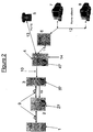
- low bandwidth copper connections 19 may be maintained between the network nodes 2, 3, in parallel with a fibre optic 9. These connections allow a basic telephone and/or narrowband internet service to be provided in the event of failure of one of the components in the optical system 9.
- a battery backup 29 can be maintained in nodes other than the distribution point 3, further towards the exchange, such as the cabinet 2. Because of the branched nature of the network, several customer equipments 4 can feed each distribution point 3, and all the customer equipments served by each of several distribution points 3 will serve a single cabinet 2, so the current drawn from each customer will be very small. These trickle currents are controlled by the respective power control units 33, 43, to prevent overcharging.
- the actual power drawn from each customer termination 4 is controlled by the power control function 33, and is the subject of our International patent application WO2009/138710 entitled "Power Supply System", which was filed concurrently with the present application.
- a fibre-fed remote node 3 also has some copper connection 19 to a cabinet 2, then it is possible to trickle-charge a battery 27 located at the cabinet from excess charge that is obtained via reverse power feed from the NTEs 4 located at the customer premises. Under power outage conditions, the battery 27 located in the cabinet 2 can change to a forwards power-feed mode which can then charge the batteries 37 located within the fibre-fed remote nodes 3.
- the ultimate aim of bi-directional power feed is to provide sufficient electrical capacity at the fibre-fed remote node 3 to power the common ONU/multiplexer circuitry and the SLICS in order to provide a 64kbit/s based lifeline POTS service - either indefinitely or for a pre-determined time defined by a service level agreement.
- the cabinet 2, distribution point 3 and customer equipment 4 each have a respective battery power backup 37, 47 associated with their respective power control units 33, 43. Under normal conditions these are maintained fully charged by means of trickle currents from the mains power feed 64kbit/s based lifeline POTS service - either indefinitely or for a pre-determined time defined by a service level agreement.
- the cabinet 2, distribution point 3 and customer equipment 4 each have a respective battery power backup 37, 47 associated with their respective power control units 33, 43. Under normal conditions these are maintained fully charged by means of trickle currents from the mains power feed 14 to the customer equipment 4, and thus over the "final drop" 10 to the distribution point.
- a battery backup 29 can also be maintained in nodes further towards the exchange, such as the cabinet 2. Because of the branched nature of the network, several customer equipments 4 can feed each distribution point 3, and all the customer equipments served by each of several distribution points 3 will serve a single cabinet 2, so the current drawn from each one will be very small. These trickle currents are controlled by the respective power control units 33, 43, to prevent overcharging.
- the main priority is to ensure sufficient power capacity at the fibre-fed remote node to provide the "lifeline" plain telephone service between the exchange 1 and the telephone handset 5 over the connections 9, 10, 13. This requires the nodes 2, 3, 4 in the network to continue to function, despite the loss of power from the mains supply 14 in the network termination equipment 4 which normally maintains them. If there is a power-outage at the network termination equipment 4 then the remote nodes 2, 3 have to rely on their local battery backup.
- the battery power 27, 37, 47 can be sufficient to maintain the service for a reasonable duration.
- the power management systems 33, 43 can be used to transfer charge from one battery 27, 37 to another over the network according to the usage, or remaining life, of each battery 27, 37, 47. Consequently, a bi-directional power feed can be used to provide sufficient electrical capacity at the fibre-fed remote node 3 to power the common ONU/multiplexer circuitry 31/32 and the subscriber line interface circuit (SLIC) in order to provide a 64kbit/s based lifeline POTS service - either indefinitely or for a pre-determined time defined by a service level agreement.
- SLIC subscriber line interface circuit
- customer equipment without provision for local power feeds may also be connected to the distribution point 3.
- the power control unit operates dynamically, to take account of different users coming on or off line, so that power is maintained when some users go off line.
- the amount of power, if any, delivered by each customer equipment may be recorded by the distribution point 3, and used to calculate an appropriate discount to each user's bill.
Landscapes
- Engineering & Computer Science (AREA)
- Signal Processing (AREA)
- Devices For Supply Of Signal Current (AREA)
- Telephonic Communication Services (AREA)
Claims (12)
- Zwischennetzwerkknoten (3) für ein Telekommunikationsnetzwerk, der dazu ausgelegt ist, eine optische Verbindung (9) und zwei oder mehr verdrahtete elektrische Kommunikationsverbindungen (10) mit jeweiligen kundenseitigen Netzwerkschnittstellenvorrichtungen (4) zu verbinden, umfassend ein Energieverwaltungssystem (33), das angeordnet ist, um dem Zwischennetzwerkknoten zu ermöglichen, elektrische Energie von den kundenseitigen Netzwerkschnittstellenvorrichtungen, die durch die verdrahteten elektrischen Kommunikationsverbindungen (10) daran angeschlossen sind, zu empfangen und an diese elektrische Energie zu liefern.
- Zwischennetzwerkknoten nach Anspruch 1, umfassend ein Kommunikationsverbindungs-Steuerungssystem zum Liefern einer ersten Kategorie von Telekommunikationsdiensten, wenn dem Zwischennetzwerkknoten von einer oder mehreren kundenseitigen Netzwerkschnittstellenvorrichtungen (4) Energie zugeführt wird, und zum Liefern einer zweiten Kategorie von Kommunikationsdiensten, wenn dem Zwischennetzwerkknoten keine Energie zugeführt wird, wobei die zweite Kategorie einen begrenzteren Dienst bereitstellt.
- Zwischennetzwerkknoten nach Anspruch 2, wobei die zweite Kategorie des Kommunikationsdienstes für alle kundenseitigen Netzwerkschnittstellenvorrichtungen bereitgestellt wird, die dem Zwischennetzwerkknoten keine Energie zuführen.
- Zwischennetzwerkknoten nach Anspruch 1, 2 oder 3, umfassend eine elektrische Speichervorrichtung (37) zum Versorgen des Zwischennetzwerkknotens und aller angeschlossenen kundenseitigen Netzschnittstellenvorrichtungen, die Energie von diesen beziehen, wenn keine externe Energieversorgung verfügbar ist, wobei das Energieverwaltungssystem (33) angeordnet ist, um die Speichervorrichtung durch eine Erhaltungsladung von allen kundenseitigen Netzschnittstellenvorrichtungen, die Energie an den Zwischennetzwerkknoten liefern, zu laden.
- Zwischennetzwerkknoten nach Anspruch 4, wenn er von Anspruch 3 abhängig ist, wobei ein Kommunikationsverbindungs-Steuerungssystem durch das Energieverwaltungssystem (33) gesteuert wird, um den Dienst gemäß der in der elektrischen Speichervorrichtung (37) gespeicherten Restladung zu begrenzen.
- Telekommunikationsnetzwerk, umfassend mehrere Zwischennetzwerkknoten (3, 9), jeweils nach einem der vorhergehenden Ansprüche, die durch ein elektrisches Kommunikationsnetzwerk (19) miteinander verbunden sind, und wobei die Energieverwaltungsmittel der Zwischennetzwerkknoten angeordnet sind, um zusammenzuarbeiten, um elektrische Energie über das elektrische Kommunikationsnetzwerk von einem oder mehreren Zwischennetzwerkknoten (3) oder kundenseitigen Netzwerkschnittstellenvorrichtungen (4) zu liefern, die eine Verbindung zu einer externen Energieversorgung aufweisen.
- Verfahren zum Zuführen elektrische Energie an Elemente eines Telekommunikationsnetzwerks, das Zwischennetzwerkknoten umfasst, wobei mindestens einige der Zwischennetzwerkknoten (3) dazu ausgelegt sind, eine optische Verbindung (9) und mehrere verdrahtete elektrische Kommunikationsverbindungen (10, 110) mit jeweiligen kundenseitigen Netzwerkschnittstellenvorrichtungen (4) zu verbinden, wobei zumindest einige der kundenseitigen Netzwerkschnittstellenvorrichtungen eine externe Energieversorgung (14) aufweisen und dazu ausgelegt sind, elektrische Energie an ihre jeweiligen Zwischennetzwerkknoten über die verdrahteten elektrischen Kommunikationsverbindungen zuzuführen, wobei das Verfahren das Liefern elektrischer Energie über die verdrahteten elektrischen Kommunikationsverbindungen (10, 110) von einem Zwischennetzwerkknoten an kundenseitige Netzwerkschnittstellenvorrichtungen umfasst, die derzeit keine andere elektrische Energieversorgung aufweisen.
- Verfahren nach Anspruch 7, wobei mindestens einige der Zwischennetzwerkknoten (3) elektrische Speichervorrichtungen (37) zum Versorgen der jeweiligen Zwischennetzwerkknoten und aller angeschlossenen kundenseitigen Netzwerkschnittstellenvorrichtungen (4) umfassen, die Energie von diesen beziehen, wenn keine andere Energieversorgung für die kundenseitigen Netzwerkschnittstellenvorrichtungen verfügbar ist, wobei die Speichervorrichtung durch Erhaltungsladungen von einer oder mehreren der kundenseitigen Netzwerkschnittstellenvorrichtungen geladen wird, wenn eine Energieversorgung für die kundenseitigen Netzwerkschnittstellenvorrichtungen verfügbar ist.
- Verfahren nach Anspruch 7 oder 8, wobei elektrische Energie durch das Netzwerk (10) von den Zwischennetzwerkknoten (3) an eine oder mehrere der kundenseitigen Netzwerkschnittstellenvorrichtungen (4) während Unterbrechungen ihrer externen Energieversorgungen geliefert werden kann.
- Verfahren nach Anspruch 9, wobei eine erste Kategorie eines Telekommunikationsdienstes für kundenseitige Netzwerkschnittstellenvorrichtungen bereitgestellt wird, die mit einem Zwischennetzwerkknoten (3) verbunden sind, über den dem Zwischennetzwerkknoten Energie zugeführt wird, und eine zweite, begrenztere Kategorie eines Kommunikationsdienstes für kundenseitige Netzwerkschnittstellenvorrichtungen bereitgestellt wird, die aktuell dem Zwischennetzwerkknoten keine Energie zuführen.
- Verfahren nach Anspruch 10, wobei eine erste Kategorie eines Telekommunikationsdienstes für kundenseitige Netzwerkschnittstellenvorrichtungen bereitgestellt wird, die einem Zwischennetzwerkknoten Energie zuführen, und eine zweite, begrenztere Kategorie eines Kommunikationsdienstes für kundenseitige Netzwerkschnittstellenvorrichtungen bereitgestellt wird, die Energie von einem Zwischennetzwerkknoten beziehen.
- Verfahren nach Anspruch 10 oder 11, wenn es von Anspruch 8 abhängig ist, wobei der bereitgestellte Dienst gemäß der verbleibenden Kapazität der Energiespeichermittel begrenzt wird.
Priority Applications (1)
| Application Number | Priority Date | Filing Date | Title |
|---|---|---|---|
| EP09746028.1A EP2286578B1 (de) | 2008-05-15 | 2009-04-21 | Leistungs-backup-system |
Applications Claiming Priority (3)
| Application Number | Priority Date | Filing Date | Title |
|---|---|---|---|
| EP08251710A EP2120442A1 (de) | 2008-05-15 | 2008-05-15 | Leistungs-Backup-System |
| EP09746028.1A EP2286578B1 (de) | 2008-05-15 | 2009-04-21 | Leistungs-backup-system |
| PCT/GB2009/001008 WO2009138711A1 (en) | 2008-05-15 | 2009-04-21 | Power backup system |
Publications (2)
| Publication Number | Publication Date |
|---|---|
| EP2286578A1 EP2286578A1 (de) | 2011-02-23 |
| EP2286578B1 true EP2286578B1 (de) | 2020-12-23 |
Family
ID=39627760
Family Applications (2)
| Application Number | Title | Priority Date | Filing Date |
|---|---|---|---|
| EP08251710A Ceased EP2120442A1 (de) | 2008-05-15 | 2008-05-15 | Leistungs-Backup-System |
| EP09746028.1A Active EP2286578B1 (de) | 2008-05-15 | 2009-04-21 | Leistungs-backup-system |
Family Applications Before (1)
| Application Number | Title | Priority Date | Filing Date |
|---|---|---|---|
| EP08251710A Ceased EP2120442A1 (de) | 2008-05-15 | 2008-05-15 | Leistungs-Backup-System |
Country Status (3)
| Country | Link |
|---|---|
| US (1) | US9300815B2 (de) |
| EP (2) | EP2120442A1 (de) |
| WO (1) | WO2009138711A1 (de) |
Families Citing this family (23)
| Publication number | Priority date | Publication date | Assignee | Title |
|---|---|---|---|---|
| EP2362626A1 (de) | 2010-02-15 | 2011-08-31 | British Telecommunications public limited company | Telefongerät, das einen Netzwerkknoten mit Energie versorgt |
| IL210374A0 (en) | 2010-12-30 | 2011-03-31 | Eci Telecom Ltd | Technique for remote power feeding in access networks |
| US8601289B1 (en) * | 2011-02-21 | 2013-12-03 | Adtran, Inc. | Optical network unit with redundant reverse powering from customer premises equipment |
| US10313533B2 (en) | 2012-03-20 | 2019-06-04 | British Telecommunications Public Limited Company | Power distribution for telecommunications system |
| EP2642688A1 (de) | 2012-03-20 | 2013-09-25 | British Telecommunications public limited company | Stromverteilung für Telekommunikationssystem |
| CN103051462A (zh) * | 2013-01-07 | 2013-04-17 | 中兴通讯股份有限公司 | 接入设备的供电方法及装置 |
| EP2830302A1 (de) | 2013-07-23 | 2015-01-28 | British Telecommunications public limited company | Rückleistungssystem für Telekommunikationsknoten |
| EP2843926B1 (de) * | 2013-09-03 | 2017-07-12 | Alcatel Lucent | Übertragungsvorrichtung mit Rückleistung |
| US10855373B2 (en) * | 2013-09-09 | 2020-12-01 | British Telecommunications Public Limited Company | Fibre network proxy |
| JP6409783B2 (ja) * | 2013-11-14 | 2018-10-24 | ソニー株式会社 | 電力供給装置 |
| EP3090532B1 (de) | 2013-12-31 | 2022-02-23 | British Telecommunications public limited company | Vorrichtung zur verwendung bei der stromversorgung über eine telefonleitung |
| TWI572182B (zh) * | 2014-01-03 | 2017-02-21 | 亞旭電腦股份有限公司 | 網路架構及其局端設備與用戶端設備 |
| US9319537B2 (en) * | 2014-04-22 | 2016-04-19 | Microsemi Corporation | Load balancing reverse power supply |
| CN106464769B (zh) * | 2014-05-16 | 2018-06-12 | 美高森美公司 | 用于反向功率馈送的装置和方法 |
| CN105227212A (zh) * | 2014-06-10 | 2016-01-06 | 中兴通讯股份有限公司 | 反向供电管理方法、装置及系统 |
| CN107078912B (zh) | 2014-08-20 | 2020-10-09 | 英国电讯有限公司 | 电信本地分配网络及其操作方法以及客户驻地设备 |
| EP3286842B1 (de) * | 2015-04-20 | 2019-03-06 | Microsemi P.O.E. Ltd. | System und verfahren zur umgekehrten stromversorgung |
| EP3099005B1 (de) * | 2015-05-26 | 2019-12-25 | Alcatel Lucent | Bereitstellung neuer breitbandkommunikation durch umgekehrte stromversorgung |
| CN105302268A (zh) * | 2015-10-20 | 2016-02-03 | 浪潮电子信息产业股份有限公司 | 一种rack机柜后备电源 |
| CA3029294C (en) | 2016-07-04 | 2024-03-12 | Microsemi P.O.E Ltd. | Reverse power feeding power sourcing equipment and method |
| EP3560116B1 (de) | 2016-12-21 | 2021-12-22 | British Telecommunications Public Limited Company | Netzwerkknoten |
| US10340977B2 (en) | 2017-07-28 | 2019-07-02 | Microsemi P.O.E Ltd. | Reverse power feeding power sourcing equipment and method |
| US10951056B2 (en) | 2018-03-07 | 2021-03-16 | At&T Intellectual Property I, L.P. | Systems and methods for intelligent power distribution |
Family Cites Families (11)
| Publication number | Priority date | Publication date | Assignee | Title |
|---|---|---|---|---|
| FI92448C (fi) | 1992-12-29 | 1994-11-10 | Nokia Telecommunications Oy | Järjestelmä jännitteen järjestämiseksi useaan sähköisen yksikön yhteiseen jännitelinjaan |
| US6028916A (en) * | 1997-12-31 | 2000-02-22 | Mediaone Group, Inc. | Method and apparatus for maintaining availability of lifeline telephony service on a hybrid fiber-coax network |
| US7116761B2 (en) * | 1998-11-30 | 2006-10-03 | Qwest Communications International Inc. | Fiber to the curb and fiber to the neighborhood power architecture |
| SE9903476L (sv) * | 1999-09-24 | 2001-03-25 | Ericsson Telefon Ab L M | Anordning och metod som avser kraftförsörjning i ett kommunikationsnätverk |
| US6947554B2 (en) * | 2001-11-08 | 2005-09-20 | Motorola, Inc. | Least mean power consumption in telecommunications systems |
| US7672591B2 (en) * | 2005-03-01 | 2010-03-02 | Soto Alexander I | System and method for a subscriber-powered network element |
| US8259929B2 (en) * | 2005-11-04 | 2012-09-04 | 2Wire, Inc. | Methods and apparatuses to provide a back up power supply for a network interface device |
| US20080028237A1 (en) * | 2006-07-26 | 2008-01-31 | Roadnarrows, Llc | Power Management Using Integrated Data and Power Interfaces |
| US8929959B2 (en) * | 2007-04-24 | 2015-01-06 | Telefonaktiebolaget L M Ericsson (Publ) | Method and a device for receiving data in a mobile communication device in a broadcast system |
| CA2620490C (en) * | 2007-10-04 | 2016-06-28 | Genesis Technical Systems Corp. | Remote powering of dsl adms |
| EP2120443A1 (de) | 2008-05-15 | 2009-11-18 | BRITISH TELECOMMUNICATIONS public limited company | Stromversorgungssystem |
-
2008
- 2008-05-15 EP EP08251710A patent/EP2120442A1/de not_active Ceased
-
2009
- 2009-04-21 WO PCT/GB2009/001008 patent/WO2009138711A1/en not_active Ceased
- 2009-04-21 EP EP09746028.1A patent/EP2286578B1/de active Active
- 2009-04-21 US US12/992,847 patent/US9300815B2/en active Active
Non-Patent Citations (1)
| Title |
|---|
| None * |
Also Published As
| Publication number | Publication date |
|---|---|
| US9300815B2 (en) | 2016-03-29 |
| EP2286578A1 (de) | 2011-02-23 |
| WO2009138711A1 (en) | 2009-11-19 |
| US20110064212A1 (en) | 2011-03-17 |
| EP2120442A1 (de) | 2009-11-18 |
Similar Documents
| Publication | Publication Date | Title |
|---|---|---|
| US9300815B2 (en) | Power backup system | |
| US8963367B2 (en) | Technique for remote power feeding in access networks | |
| EP2120443A1 (de) | Stromversorgungssystem | |
| JP3218538B2 (ja) | 同軸ケーブルネットワークへの電力供給方法及び装置 | |
| US6804536B1 (en) | Wireless communications interface | |
| KR0135508B1 (ko) | 전화 교환 시스템과, 데이터 액세스 장치로부터 고객 구내 장치를 액세스 하는 방법 | |
| CN105493486B (zh) | 用于电信节点的反向供电系统 | |
| EP1189422B1 (de) | Vorrichtung und Verfahren zur Bereitstellung von Leistungsnotdiensten für DSL-Teilnehmern | |
| EP2362626A1 (de) | Telefongerät, das einen Netzwerkknoten mit Energie versorgt | |
| CN1319319C (zh) | 在一个通信网络中有关电源的一种配置和方法 | |
| EP1089538A1 (de) | Ein System zum Bereitstellen eines IP-Fernsprechdienstes in Notfalle auf Kabelanschaltnetzen | |
| EP1084564A2 (de) | System und verfahren zur vermittlung von stimme und daten über ein lokales paketnetzwerk | |
| CA2730020A1 (en) | Synchronization of communication equipment | |
| EP2829015B1 (de) | Stromverteilung für telekommunikationssystem | |
| US20020151302A1 (en) | Lifeline backup system and method for telephone networks | |
| JP2002534851A (ja) | 通信設備内での電力制限呼処理のシステムおよび方法 | |
| EP2642688A1 (de) | Stromverteilung für Telekommunikationssystem | |
| CN101908965B (zh) | 一种光网络单元、电话系统及相应的呼叫响应方法 | |
| US20030033262A1 (en) | Line connection controller | |
| Jhunjhunwala | Affordable fibre access network for developing countries | |
| Lin | Migration of home information system toward ISDN | |
| JP2005159617A (ja) | 通話システム | |
| MXPA00009327A (en) | A system to provide lifeline ip telephony service on cable access networks |
Legal Events
| Date | Code | Title | Description |
|---|---|---|---|
| PUAI | Public reference made under article 153(3) epc to a published international application that has entered the european phase |
Free format text: ORIGINAL CODE: 0009012 |
|
| 17P | Request for examination filed |
Effective date: 20101018 |
|
| AK | Designated contracting states |
Kind code of ref document: A1 Designated state(s): AT BE BG CH CY CZ DE DK EE ES FI FR GB GR HR HU IE IS IT LI LT LU LV MC MK MT NL NO PL PT RO SE SI SK TR |
|
| AX | Request for extension of the european patent |
Extension state: AL BA RS |
|
| DAX | Request for extension of the european patent (deleted) | ||
| STAA | Information on the status of an ep patent application or granted ep patent |
Free format text: STATUS: EXAMINATION IS IN PROGRESS |
|
| 17Q | First examination report despatched |
Effective date: 20161107 |
|
| RAP1 | Party data changed (applicant data changed or rights of an application transferred) |
Owner name: BRITISH TELECOMMUNICATIONS PUBLIC LIMITED COMPANY |
|
| GRAP | Despatch of communication of intention to grant a patent |
Free format text: ORIGINAL CODE: EPIDOSNIGR1 |
|
| STAA | Information on the status of an ep patent application or granted ep patent |
Free format text: STATUS: GRANT OF PATENT IS INTENDED |
|
| INTG | Intention to grant announced |
Effective date: 20200720 |
|
| GRAS | Grant fee paid |
Free format text: ORIGINAL CODE: EPIDOSNIGR3 |
|
| GRAA | (expected) grant |
Free format text: ORIGINAL CODE: 0009210 |
|
| STAA | Information on the status of an ep patent application or granted ep patent |
Free format text: STATUS: THE PATENT HAS BEEN GRANTED |
|
| AK | Designated contracting states |
Kind code of ref document: B1 Designated state(s): AT BE BG CH CY CZ DE DK EE ES FI FR GB GR HR HU IE IS IT LI LT LU LV MC MK MT NL NO PL PT RO SE SI SK TR |
|
| REG | Reference to a national code |
Ref country code: GB Ref legal event code: FG4D |
|
| REG | Reference to a national code |
Ref country code: DE Ref legal event code: R096 Ref document number: 602009063203 Country of ref document: DE |
|
| REG | Reference to a national code |
Ref country code: AT Ref legal event code: REF Ref document number: 1348819 Country of ref document: AT Kind code of ref document: T Effective date: 20210115 |
|
| REG | Reference to a national code |
Ref country code: IE Ref legal event code: FG4D |
|
| PG25 | Lapsed in a contracting state [announced via postgrant information from national office to epo] |
Ref country code: GR Free format text: LAPSE BECAUSE OF FAILURE TO SUBMIT A TRANSLATION OF THE DESCRIPTION OR TO PAY THE FEE WITHIN THE PRESCRIBED TIME-LIMIT Effective date: 20210324 Ref country code: FI Free format text: LAPSE BECAUSE OF FAILURE TO SUBMIT A TRANSLATION OF THE DESCRIPTION OR TO PAY THE FEE WITHIN THE PRESCRIBED TIME-LIMIT Effective date: 20201223 Ref country code: NO Free format text: LAPSE BECAUSE OF FAILURE TO SUBMIT A TRANSLATION OF THE DESCRIPTION OR TO PAY THE FEE WITHIN THE PRESCRIBED TIME-LIMIT Effective date: 20210323 |
|
| REG | Reference to a national code |
Ref country code: AT Ref legal event code: MK05 Ref document number: 1348819 Country of ref document: AT Kind code of ref document: T Effective date: 20201223 |
|
| REG | Reference to a national code |
Ref country code: NL Ref legal event code: MP Effective date: 20201223 |
|
| PG25 | Lapsed in a contracting state [announced via postgrant information from national office to epo] |
Ref country code: LV Free format text: LAPSE BECAUSE OF FAILURE TO SUBMIT A TRANSLATION OF THE DESCRIPTION OR TO PAY THE FEE WITHIN THE PRESCRIBED TIME-LIMIT Effective date: 20201223 Ref country code: SE Free format text: LAPSE BECAUSE OF FAILURE TO SUBMIT A TRANSLATION OF THE DESCRIPTION OR TO PAY THE FEE WITHIN THE PRESCRIBED TIME-LIMIT Effective date: 20201223 Ref country code: BG Free format text: LAPSE BECAUSE OF FAILURE TO SUBMIT A TRANSLATION OF THE DESCRIPTION OR TO PAY THE FEE WITHIN THE PRESCRIBED TIME-LIMIT Effective date: 20210323 |
|
| PG25 | Lapsed in a contracting state [announced via postgrant information from national office to epo] |
Ref country code: HR Free format text: LAPSE BECAUSE OF FAILURE TO SUBMIT A TRANSLATION OF THE DESCRIPTION OR TO PAY THE FEE WITHIN THE PRESCRIBED TIME-LIMIT Effective date: 20201223 Ref country code: NL Free format text: LAPSE BECAUSE OF FAILURE TO SUBMIT A TRANSLATION OF THE DESCRIPTION OR TO PAY THE FEE WITHIN THE PRESCRIBED TIME-LIMIT Effective date: 20201223 |
|
| REG | Reference to a national code |
Ref country code: LT Ref legal event code: MG9D |
|
| PG25 | Lapsed in a contracting state [announced via postgrant information from national office to epo] |
Ref country code: CZ Free format text: LAPSE BECAUSE OF FAILURE TO SUBMIT A TRANSLATION OF THE DESCRIPTION OR TO PAY THE FEE WITHIN THE PRESCRIBED TIME-LIMIT Effective date: 20201223 Ref country code: EE Free format text: LAPSE BECAUSE OF FAILURE TO SUBMIT A TRANSLATION OF THE DESCRIPTION OR TO PAY THE FEE WITHIN THE PRESCRIBED TIME-LIMIT Effective date: 20201223 Ref country code: PT Free format text: LAPSE BECAUSE OF FAILURE TO SUBMIT A TRANSLATION OF THE DESCRIPTION OR TO PAY THE FEE WITHIN THE PRESCRIBED TIME-LIMIT Effective date: 20210423 Ref country code: SK Free format text: LAPSE BECAUSE OF FAILURE TO SUBMIT A TRANSLATION OF THE DESCRIPTION OR TO PAY THE FEE WITHIN THE PRESCRIBED TIME-LIMIT Effective date: 20201223 Ref country code: RO Free format text: LAPSE BECAUSE OF FAILURE TO SUBMIT A TRANSLATION OF THE DESCRIPTION OR TO PAY THE FEE WITHIN THE PRESCRIBED TIME-LIMIT Effective date: 20201223 Ref country code: LT Free format text: LAPSE BECAUSE OF FAILURE TO SUBMIT A TRANSLATION OF THE DESCRIPTION OR TO PAY THE FEE WITHIN THE PRESCRIBED TIME-LIMIT Effective date: 20201223 |
|
| PG25 | Lapsed in a contracting state [announced via postgrant information from national office to epo] |
Ref country code: AT Free format text: LAPSE BECAUSE OF FAILURE TO SUBMIT A TRANSLATION OF THE DESCRIPTION OR TO PAY THE FEE WITHIN THE PRESCRIBED TIME-LIMIT Effective date: 20201223 Ref country code: PL Free format text: LAPSE BECAUSE OF FAILURE TO SUBMIT A TRANSLATION OF THE DESCRIPTION OR TO PAY THE FEE WITHIN THE PRESCRIBED TIME-LIMIT Effective date: 20201223 |
|
| REG | Reference to a national code |
Ref country code: DE Ref legal event code: R097 Ref document number: 602009063203 Country of ref document: DE |
|
| PG25 | Lapsed in a contracting state [announced via postgrant information from national office to epo] |
Ref country code: IS Free format text: LAPSE BECAUSE OF FAILURE TO SUBMIT A TRANSLATION OF THE DESCRIPTION OR TO PAY THE FEE WITHIN THE PRESCRIBED TIME-LIMIT Effective date: 20210423 |
|
| PG25 | Lapsed in a contracting state [announced via postgrant information from national office to epo] |
Ref country code: IT Free format text: LAPSE BECAUSE OF FAILURE TO SUBMIT A TRANSLATION OF THE DESCRIPTION OR TO PAY THE FEE WITHIN THE PRESCRIBED TIME-LIMIT Effective date: 20201223 |
|
| PLBE | No opposition filed within time limit |
Free format text: ORIGINAL CODE: 0009261 |
|
| STAA | Information on the status of an ep patent application or granted ep patent |
Free format text: STATUS: NO OPPOSITION FILED WITHIN TIME LIMIT |
|
| PG25 | Lapsed in a contracting state [announced via postgrant information from national office to epo] |
Ref country code: MC Free format text: LAPSE BECAUSE OF FAILURE TO SUBMIT A TRANSLATION OF THE DESCRIPTION OR TO PAY THE FEE WITHIN THE PRESCRIBED TIME-LIMIT Effective date: 20201223 Ref country code: DK Free format text: LAPSE BECAUSE OF FAILURE TO SUBMIT A TRANSLATION OF THE DESCRIPTION OR TO PAY THE FEE WITHIN THE PRESCRIBED TIME-LIMIT Effective date: 20201223 Ref country code: ES Free format text: LAPSE BECAUSE OF FAILURE TO SUBMIT A TRANSLATION OF THE DESCRIPTION OR TO PAY THE FEE WITHIN THE PRESCRIBED TIME-LIMIT Effective date: 20201223 |
|
| 26N | No opposition filed |
Effective date: 20210924 |
|
| PG25 | Lapsed in a contracting state [announced via postgrant information from national office to epo] |
Ref country code: LU Free format text: LAPSE BECAUSE OF NON-PAYMENT OF DUE FEES Effective date: 20210421 |
|
| REG | Reference to a national code |
Ref country code: BE Ref legal event code: MM Effective date: 20210430 |
|
| PG25 | Lapsed in a contracting state [announced via postgrant information from national office to epo] |
Ref country code: CH Free format text: LAPSE BECAUSE OF NON-PAYMENT OF DUE FEES Effective date: 20210430 Ref country code: LI Free format text: LAPSE BECAUSE OF NON-PAYMENT OF DUE FEES Effective date: 20210430 |
|
| PG25 | Lapsed in a contracting state [announced via postgrant information from national office to epo] |
Ref country code: SI Free format text: LAPSE BECAUSE OF FAILURE TO SUBMIT A TRANSLATION OF THE DESCRIPTION OR TO PAY THE FEE WITHIN THE PRESCRIBED TIME-LIMIT Effective date: 20201223 |
|
| PG25 | Lapsed in a contracting state [announced via postgrant information from national office to epo] |
Ref country code: IE Free format text: LAPSE BECAUSE OF NON-PAYMENT OF DUE FEES Effective date: 20210421 |
|
| PG25 | Lapsed in a contracting state [announced via postgrant information from national office to epo] |
Ref country code: IS Free format text: LAPSE BECAUSE OF FAILURE TO SUBMIT A TRANSLATION OF THE DESCRIPTION OR TO PAY THE FEE WITHIN THE PRESCRIBED TIME-LIMIT Effective date: 20210423 |
|
| PG25 | Lapsed in a contracting state [announced via postgrant information from national office to epo] |
Ref country code: BE Free format text: LAPSE BECAUSE OF NON-PAYMENT OF DUE FEES Effective date: 20210430 |
|
| PG25 | Lapsed in a contracting state [announced via postgrant information from national office to epo] |
Ref country code: HU Free format text: LAPSE BECAUSE OF FAILURE TO SUBMIT A TRANSLATION OF THE DESCRIPTION OR TO PAY THE FEE WITHIN THE PRESCRIBED TIME-LIMIT; INVALID AB INITIO Effective date: 20090421 Ref country code: CY Free format text: LAPSE BECAUSE OF FAILURE TO SUBMIT A TRANSLATION OF THE DESCRIPTION OR TO PAY THE FEE WITHIN THE PRESCRIBED TIME-LIMIT Effective date: 20201223 |
|
| P01 | Opt-out of the competence of the unified patent court (upc) registered |
Effective date: 20230623 |
|
| PG25 | Lapsed in a contracting state [announced via postgrant information from national office to epo] |
Ref country code: MK Free format text: LAPSE BECAUSE OF FAILURE TO SUBMIT A TRANSLATION OF THE DESCRIPTION OR TO PAY THE FEE WITHIN THE PRESCRIBED TIME-LIMIT Effective date: 20201223 |
|
| PG25 | Lapsed in a contracting state [announced via postgrant information from national office to epo] |
Ref country code: TR Free format text: LAPSE BECAUSE OF FAILURE TO SUBMIT A TRANSLATION OF THE DESCRIPTION OR TO PAY THE FEE WITHIN THE PRESCRIBED TIME-LIMIT Effective date: 20201223 |
|
| PG25 | Lapsed in a contracting state [announced via postgrant information from national office to epo] |
Ref country code: MT Free format text: LAPSE BECAUSE OF FAILURE TO SUBMIT A TRANSLATION OF THE DESCRIPTION OR TO PAY THE FEE WITHIN THE PRESCRIBED TIME-LIMIT Effective date: 20201223 |
|
| PGFP | Annual fee paid to national office [announced via postgrant information from national office to epo] |
Ref country code: DE Payment date: 20250319 Year of fee payment: 17 |
|
| PGFP | Annual fee paid to national office [announced via postgrant information from national office to epo] |
Ref country code: GB Payment date: 20260319 Year of fee payment: 18 |
|
| PGFP | Annual fee paid to national office [announced via postgrant information from national office to epo] |
Ref country code: FR Payment date: 20260320 Year of fee payment: 18 |