EP2287070A2 - Système de chargement de charges lourdes - Google Patents
Système de chargement de charges lourdes Download PDFInfo
- Publication number
- EP2287070A2 EP2287070A2 EP10007154A EP10007154A EP2287070A2 EP 2287070 A2 EP2287070 A2 EP 2287070A2 EP 10007154 A EP10007154 A EP 10007154A EP 10007154 A EP10007154 A EP 10007154A EP 2287070 A2 EP2287070 A2 EP 2287070A2
- Authority
- EP
- European Patent Office
- Prior art keywords
- support structure
- ship
- loading system
- crane runway
- heavy
- Prior art date
- Legal status (The legal status is an assumption and is not a legal conclusion. Google has not performed a legal analysis and makes no representation as to the accuracy of the status listed.)
- Withdrawn
Links
- 238000000034 method Methods 0.000 claims abstract description 15
- 241000282326 Felis catus Species 0.000 claims description 6
- 241000238633 Odonata Species 0.000 claims description 6
- 230000008878 coupling Effects 0.000 claims description 6
- 238000010168 coupling process Methods 0.000 claims description 6
- 238000005859 coupling reaction Methods 0.000 claims description 6
- 239000000969 carrier Substances 0.000 description 9
- 238000005452 bending Methods 0.000 description 4
- 238000005096 rolling process Methods 0.000 description 4
- 238000005259 measurement Methods 0.000 description 3
- 230000003247 decreasing effect Effects 0.000 description 2
- 230000001419 dependent effect Effects 0.000 description 2
- 238000003032 molecular docking Methods 0.000 description 2
- 240000006829 Ficus sundaica Species 0.000 description 1
- 230000002411 adverse Effects 0.000 description 1
- 238000004891 communication Methods 0.000 description 1
- 230000000694 effects Effects 0.000 description 1
- 238000007667 floating Methods 0.000 description 1
- 239000012530 fluid Substances 0.000 description 1
- 238000012544 monitoring process Methods 0.000 description 1
- UUORTJUPDJJXST-UHFFFAOYSA-N n-(2-hydroxyethyl)prop-2-enamide Chemical compound OCCNC(=O)C=C UUORTJUPDJJXST-UHFFFAOYSA-N 0.000 description 1
- 230000003068 static effect Effects 0.000 description 1
- 239000000758 substrate Substances 0.000 description 1
- XLYOFNOQVPJJNP-UHFFFAOYSA-N water Substances O XLYOFNOQVPJJNP-UHFFFAOYSA-N 0.000 description 1
- 239000003643 water by type Substances 0.000 description 1
Images


Classifications
-
- B—PERFORMING OPERATIONS; TRANSPORTING
- B63—SHIPS OR OTHER WATERBORNE VESSELS; RELATED EQUIPMENT
- B63B—SHIPS OR OTHER WATERBORNE VESSELS; EQUIPMENT FOR SHIPPING
- B63B27/00—Arrangement of ship-based loading or unloading equipment for cargo or passengers
- B63B27/10—Arrangement of ship-based loading or unloading equipment for cargo or passengers of cranes
- B63B27/12—Arrangement of ship-based loading or unloading equipment for cargo or passengers of cranes of gantry type
Definitions
- the present invention relates to a heavy load loading system and a method for loading and / or unloading of ships.
- portal cranes For loading and unloading of ships often portal cranes are used, which have a cantilevered crane runway carrier, which extends beyond the ship to be loaded in order to lower the goods to be loaded on the ship or lift from there.
- a cantilevered crane runway carrier which extends beyond the ship to be loaded in order to lower the goods to be loaded on the ship or lift from there.
- the maximum load of known ship cranes is also limited by the fact that they derive both their own weight and that of the goods to be moved into the ground on which they are built.
- the bearing capacity of the subsurface and in particular the Grundbruchwiderstand significantly affects the maximum load of known ship cranes, with the result that extremely heavy loads such as transformers, presses or power turbine turbines are not moved with conventional ship cranes or only with the help of auxiliary measures such as additional cranes can.
- the invention is therefore based on the object of a heavy load loading system and a method for loading and / or unloading of ships to move even extremely heavy loads such as transformers, presses or power plant turbines.
- the heavy-duty loading system has at least one crane runway girder along which a lifting trolley can be moved beyond the ship to be loaded and / or unloaded, the at least one gantry girder on a first support structure on the shore side and on a second support structure on the ship side, which is located on the loading and / or unloading ship is stored.
- the invention it is thus proposed for the first time to provide a second support for the usually cantilevered crane runway girder, which is located on the ship to be loaded and / or unloaded and thus supports or supports the usually freely projecting end of the gantry support.
- the weight of the crane runway girder itself as well as the weight of the goods to be moved is thus proportionately derived via the shore-side support structure into the ground and the ship-side support structure in the ship, whereby the Grundbruchgefahr the substrate on which the first land-side support structure is reduced.
- the ship-side support structure is designed such that with the heavy load loading system to be loaded goods hanging on the hoist up in the inner region of the support structures are conveyed.
- the ship-side support structure for example, have a U-shaped plan, as this can ensure that goods to be loaded on the hoist hanging through the opening of the "U" can be transported into the inner region of the support structures.
- the heavy-duty loading system may comprise two mutually parallel crane runway girders, both of which are mounted on the land side on the first support structure and on the ship side on the second support structure.
- the weight of the loads to be moved is thus, before it is introduced into the two support structures, split on two crane runway beams, so that each of the two crane runway again undergoes less bending moment and shear force, which means inversely an increase in the maximum load.
- the heavy load loading system can comprise at least one, preferably two, cat carriers which can be moved together along the crane runway carriers, which span the distance between the two crane runway carriers.
- At least one, preferably two hoists may be provided on each of the cat carriers, which may be, for example, cable or chain hoists or rope or chain winches.
- the cat carriers may be, for example, cable or chain hoists or rope or chain winches.
- strand jacks are used as hoists, since loads of several 100 t can be lifted with such strand jacks, so that the hoist has no relevant influence on the maximum load capacity of the heavy-load loading system.
- the heavy-duty loading system according to the invention is suitable for moving extremely heavy loads
- the draft of the ship loading and / or unloading with the heavy-duty loading system according to the invention will generally not change or will only change slightly, since the buoyancy of the ship is generally high will be many times greater than the loads to be moved.
- the respective ship can thus be regarded as a kind of infinite rigid support to which the ship-side support structure releases its loads.
- the first support structure and / or the second support structure to compensate for load-induced inclination changes of the crane runway carrier are adjustable in height, including the first support structure and / or the second support structure can have telescopic, preferably hydraulically telescopic supports. If, in fact, the draft of the ship to be loaded should change during the loading process, this draft change has an effect on the inclination of the crane runway girder as a result of the bearing of the crane runway girder via the second ship-side support structure.
- the heavy-duty loading system may comprise a control device according to another embodiment, which continuously changes the height of the first support structure and / or the second support structure, evaluating the Kranbahnanineist.
- the control device evaluates, for example, the measurement results generated by the digital spirit level and generates corresponding control signals, by which an actuator for adjusting the height of the respective support structure can be made to make the desired height adjustment.
- the second or the ship-side support structure may include at least two stackable modules, wherein the upper module is preferably releasably connected to the at least one crane runway girder.
- This embodiment may prove to be advantageous in particular when different and in particular different sized ships are to be loaded with the heavy-duty loading system according to the invention since, depending on the size of the ship and the structure, different levels of support structures on the ship are required.
- the present embodiment allows the ship-side support structure to comprise at least two stackable modules, only the lower module, in different high embodiments must be maintained in order to bridge the height difference to the lower edge of the upper module.
- the ship-side support structure in at least two stackable modules to subdivide thus turns out to be advantageous that, for example, the lower module can be an integral part of the ship, so that this lower module are effectively regarded as an adapter for coupling to the heavy-load loading system according to the invention can.
- the respective crane runway carrier only a single support point on the shore-side support structure in order to prevent unwanted forced voltages are introduced into the respective crane runway carrier, which can be caused by a multiple storage.
- the respective crane runway girder can thus slightly deflect due to the load, without any forced-cut sizes occurring, as may be the case with statically overdetermined systems.
- the support, on which the at least one crane runway support is mounted on the first support structure is a monovalent bearing displaceable in the longitudinal direction of the at least one crane runway support.
- each crane runway carrier is mounted on two supports on the second support structure and preferably releasably connected thereto, wherein a load balancing device, preferably a hydraulic coupling is provided which automatically performs load balancing between the supports on which the respective crane runway carrier on the second support structure is stored.
- each support comprises a piston-cylinder unit, which are in fluid communication with each other, whereby load-induced deformations of the one bearing can be converted into corresponding opposite deformations of the other bearing, which corresponds to a load balance between the respective camps.
- the object underlying the invention is also achieved with a method for loading and / or unloading ships, which has the features of claim 13.
- a method for loading and / or unloading ships which has the features of claim 13.
- the inventive method for loading and / or unloading of ships runs so that first a land-side support structure and a ship-side support structure, which is located on the loading and / or unloading ship, are created on which then stored at least one crane runway becomes. Subsequently, goods to be loaded are then loaded using a trolley having a hoist, which is movable along the at least one crane runway carrier.
- the crane track carrier inclination is actively changed by preferably changing the height of the ship-side support structure and / or the shore-side support structure. This can be done, for example, that an operator continuously crane runner inclination using a sensor attached thereto, for. As a dragonfly or digital spirit level, monitored.
- the operator can activate an actuation actuator, such as a hydraulic pump, to hydraulically telescope in or out the supports of the affected support structure, for example in the area of the supports Piston-cylinder units are to be arranged.
- an actuation actuator such as a hydraulic pump
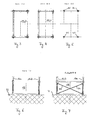
- the Fig. 1 shows a heavy-load loading system 10 according to the invention in a side view.
- the heavy duty loading system 10 is adapted to load a ship S floating in a body of water G with extremely heavy goods such as transformers, presses or power plant turbines or to clear the ship S.
- the heavy-load loading system 10 has two mutually parallel crane runway girders 16a, 16b, which may, for example, be I-girders of the IPE, HEAA, HEA, HEB or HEM series.
- the crane runway girders 16a, 16b are preferably designed as closed hollow-profile boxes with a height dimension of the order of 150 cm to 250 cm, as shown in FIG Fig. 6 to 11 can be removed.
- the heavy duty loading system 10 further comprises a first land-side support structure 12, which may for example be erected on the subsurface U of a harbor, and a second ship-side support structure 14 which extends into the hull of the ship S and stands up there.
- the two crane runway girders 16a, 16b are mounted on the first support structure 12 on the shore and on the second support structure 14 on the ship.
- each of the two crane runway girder 16a, 16b thus the static system of a single-frame carrier is based, in which both the maximum bending moment and the maximum occurring lateral force is smaller than in a cantilevered crane runway girder.
- Fig. 2 how best of all Fig. 2 can be removed, extend between the two parallel crane runway girders 16a, 16b two trolley 18 forming Katzlini 20a, 20b, which are not shown in detail on sliding or rolling means on the upper flange of the two crane runway girder 16a, 16b in the longitudinal direction of the same.
- the trolley 18 may also be formed by more or less than two cat carriers.
- the trolley 18 has a total of four synchronously operable hoists 22, which may preferably be stranded jacks, as can be lifted with such strand jacks loads of several 100 t, so that hoist 22 has no relevant influence on the maximum load capacity of the heavy load loading system 10 has.
- the two support structures 12, 14 are spatial frames with rigid and preferably concave frame corners (see, for example, FIG. Fig. 7 . Fig. 1 ), whereby not only the spatial rigidity of the support structures 12, 14 but also the maximum occurring internal internal forces, which are caused by the corner moments, can be kept small.
- the support structures 12, 14 are thus each formed by three frames, which are arranged and oriented relative to each other so that they form a U-shape in plan view, as for example the 3 and 4 can be removed.
- the mutually perpendicular frames are divided each with a common corner support.
- the support structures 12, 14 Due to the fact that the support structures 12, 14 have a U-shape in the plan view, it is possible to transport goods to be suspended on the trolley 18 or the hoists 22 in particular into the inner area of the ship-side support structure 14 and there to the ship S, which it is to be loaded, can be discontinued. Also, in this way, a discharge of the ship S is possible by goods that are located in the interior of the U-shape of the ship-side support structure 14 on the ship S, raised from there by means of the trolley 18 and the hoists 22 and out of the area the ship-side support structure 14 are conveyed out.
- both the frame panels extending in the longitudinal direction of the crane runway girders 16a, 16b and the transversely extending outer frame panels can be stiffened by bandages 24 in the form of crossing bars or ropes.
- bandages 24 in the form of crossing bars or ropes.
- only the said U-shape forming frame or their supports can be stiffened with bandages, whereas the two inner supports of the two support structures 12, 14 should not be stiffened by bandages, as this the transport of hanging on the hoists 22 Goods in the area of the land-side support structure 12 in the inner region of the ship-side support structure 14 or vice versa would be hindered.
- the ship-side support structure 14 is height-adjustable, as shown in FIG Fig. 1 indicated by the arrows H.
- This height adjustment H can be at a draft change take advantage of the ship S to the extent that the height adjustment H, the height of the support structure 14 can be increased or decreased by the same amount by which the draft of the ship S or has decreased. In this way it can be prevented that the crane runway girders 16a, 16b experience an undesired change in inclination.
- the support structure 14 in the illustrated embodiment has telescopic, preferably hydraulically telescoping supports 26 (FIG. Fig. 1 ), so that any depth changes of the ship S can be compensated continuously or in real time by actuation of associated actuation actuators (not recognizable).
- a dragonfly 28 and / or a digital spirit level 28 is provided in the area of the gantry girders 16a, 16b so as to reduce the inclination of the crane girder 16a, 16b continuously monitor respective crane runway girder 16a, 16b and, if appropriate, either manually or using a corresponding control device to cause the aforementioned actuator to vary the height of the supports 26 of the support structure 14.
- the ship-side support structure 14 consists of at least two stackable U-shaped frame modules 14.1, 14.2, wherein the upper frame module 14.2 with each the two crane runway girders 16a, 16b can be detachably connected via two strap connections 30.
- the upper frame module 14.2 can thus be attributed to a certain extent the stationary, land-side part of the heavy load loading system 10, whereas the lower frame module 14.1 can be attributed to the ship S, which allows each ship S, be with the inventive heavy-load loading system 10 be - or to be unloaded, has its own frame module 14.1 to compensate for the height difference to the lower edge of the upper frame module 14.2 can.
- the lower frame module 14.1 or its supports 26 therefore do not have to have such a large telescopic lift that the height difference can thus be bridged to the lower edge of the crane runway girders 16a, 16b.
- the two support points 30 on which each of the crane runway girders 16a, 16b rests on the support structure 14 are provided by a load balancing device such as a hydraulic coupling K interconnected so as to ensure a load balance between the support points 30. In this way it can be ensured that the support structure 14 is always uniformly loaded, whereby the risk of buckling individual supports is reduced by any overload.
- the two crane runway girders 16a, 16b are mounted on the landside support structure 12 only at a single support point 32 in the form of a monovalent support, which permits longitudinal movement of the crane run girders 16a, 16b with respect to the shore support structure 12.
- an already pre-assembled lower, ship-side frame module 14.1 can subsequently be fitted into the fuselage, for example with a mobile crane (not shown) of the ship S are lifted, if the ship S does not already have such a lower frame module 14.1 itself.
- an already preassembled second or upper frame module 14.2 is placed on the lower frame module 14.1 with the mobile crane, so that then placed on the two so constructed support structures 12, 14 with the help of the mobile crane, the two crane runway girder 16a, 16b in the manner explained above or can be stored.
- the unit consisting of gantry girders 16a, 16b and upper frame module 14.2 can also be brought into position as a whole with the aid of the mobile crane. After finally the trolley 18 with the mobile crane on the two crane runway girders 16a, 16b was discontinued, then the operation of the heavy duty loading system 10 can be recorded.
- a heavy load loading system is proposed for the first time, which at least partially discharges its loads to a ship to be loaded or unloaded.
Landscapes
- Chemical & Material Sciences (AREA)
- Engineering & Computer Science (AREA)
- Combustion & Propulsion (AREA)
- Mechanical Engineering (AREA)
- Ocean & Marine Engineering (AREA)
- Ship Loading And Unloading (AREA)
Applications Claiming Priority (1)
| Application Number | Priority Date | Filing Date | Title |
|---|---|---|---|
| DE200910032887 DE102009032887A1 (de) | 2009-07-13 | 2009-07-13 | Schwerlast-Verladesystem |
Publications (2)
| Publication Number | Publication Date |
|---|---|
| EP2287070A2 true EP2287070A2 (fr) | 2011-02-23 |
| EP2287070A3 EP2287070A3 (fr) | 2012-12-05 |
Family
ID=43382751
Family Applications (1)
| Application Number | Title | Priority Date | Filing Date |
|---|---|---|---|
| EP10007154A Withdrawn EP2287070A3 (fr) | 2009-07-13 | 2010-07-12 | Système de chargement de charges lourdes |
Country Status (2)
| Country | Link |
|---|---|
| EP (1) | EP2287070A3 (fr) |
| DE (1) | DE102009032887A1 (fr) |
Cited By (1)
| Publication number | Priority date | Publication date | Assignee | Title |
|---|---|---|---|---|
| CN108689308A (zh) * | 2018-07-17 | 2018-10-23 | 东台市富康机械有限公司 | 具有浮体支承的门式起重机 |
Families Citing this family (1)
| Publication number | Priority date | Publication date | Assignee | Title |
|---|---|---|---|---|
| DE102009051986B4 (de) * | 2009-11-05 | 2020-09-03 | August Alborn Gmbh & Co. Kg | Vorrichtung zum Umsetzen von Schwerlast von einem Wasserfahrzeug an Land oder umgekehrt |
Family Cites Families (8)
| Publication number | Priority date | Publication date | Assignee | Title |
|---|---|---|---|---|
| GB621818A (en) * | 1946-10-30 | 1949-04-20 | Charles Edward Dougherty | Improvements relating to the loading and unloading of ships |
| DE802532C (de) * | 1948-10-31 | 1951-02-15 | Maschf Augsburg Nuernberg Ag | Verladeeinrichtung fuer See- und Binnenhaefen |
| SE419325B (sv) * | 1976-06-11 | 1981-07-27 | Resmastservice Ab | Sett for att lasta och lossa tunga kollin pa fartyg samt anordning for settets genomforande |
| DE3101438C2 (de) * | 1981-01-17 | 1985-11-21 | ZF-Herion-Systemtechnik GmbH, 7990 Friedrichshafen | Hebe- und Senkeinrichtung mit einem Regelsystem zur Vermeidung von Schrägstellungen horizontal zu haltender Baukörper |
| WO1990008093A1 (fr) * | 1989-01-20 | 1990-07-26 | Norman Tonkin | Grue a conteneurs |
| NO168937C (no) * | 1989-04-26 | 1992-04-22 | Jebsen Skipsrederi | Anordning ved stykkgodsskip med sideportaapninger. |
| NL1002362C2 (nl) * | 1996-02-15 | 1997-08-18 | Johannes Hubertus Kieboom | Onderbouwconstructie met slagzij minimaliserende draagconstructie voor zwenkkraan op binnenvaartuig. |
| CN101279640B (zh) * | 2008-05-16 | 2013-07-10 | 游勇 | 船岸双支撑式货物装卸船机 |
-
2009
- 2009-07-13 DE DE200910032887 patent/DE102009032887A1/de not_active Withdrawn
-
2010
- 2010-07-12 EP EP10007154A patent/EP2287070A3/fr not_active Withdrawn
Non-Patent Citations (1)
| Title |
|---|
| None |
Cited By (1)
| Publication number | Priority date | Publication date | Assignee | Title |
|---|---|---|---|---|
| CN108689308A (zh) * | 2018-07-17 | 2018-10-23 | 东台市富康机械有限公司 | 具有浮体支承的门式起重机 |
Also Published As
| Publication number | Publication date |
|---|---|
| EP2287070A3 (fr) | 2012-12-05 |
| DE102009032887A1 (de) | 2011-01-20 |
Similar Documents
| Publication | Publication Date | Title |
|---|---|---|
| DE60126984T2 (de) | Verfahren und vorrichtung zur anordnung mindestens einer windturbine an offenem wasser | |
| DE4024135C1 (fr) | ||
| DE60013310T2 (de) | Meeresbauwerk | |
| WO2008046728A1 (fr) | Chariot de transport relié au sol, en particulier pour le transport de conteneurs | |
| DE2802249A1 (de) | Stabilisierungseinrichtung fuer ein kran-arbeitsschiff | |
| DE69913923T2 (de) | Drehkran und seiner Verwendung | |
| DE102015006117A1 (de) | Verfahren zum Betrieb eines Krans und Kran | |
| DE2641027A1 (de) | Kran zum verladen von umschlagguetern einheitlicher abmessungen | |
| DE102007039778A1 (de) | Flurgebundenes Transportfahrzeug, insbesondere für den Transport von Containern | |
| DE60101160T2 (de) | Fördersystem für lasten | |
| DE102006015307A1 (de) | Mobiler Großkran | |
| DE2748340C2 (de) | Kletterkran | |
| DE102011120408A1 (de) | Lastaufnahmeeinrichtung zum Anheben von schweren Anlagenteilen, insbesondere von Offshore-Anlagen | |
| EP0775080B1 (fr) | Systeme de levage de charges | |
| EP2287070A2 (fr) | Système de chargement de charges lourdes | |
| DE1506280B1 (de) | Einrichtung zum Transport und zum Stauen von Lastkaehnen auf einem Hochseelastkahntraeger | |
| EP3494259B1 (fr) | Dispositif d'étaiement de pont pour l'étaiement d'un segment de pont et procédé pour faire fonctionner des dispositifs d'étaiement de pont | |
| DE102009051986B4 (de) | Vorrichtung zum Umsetzen von Schwerlast von einem Wasserfahrzeug an Land oder umgekehrt | |
| DE4002289C2 (fr) | ||
| DE19833184C2 (de) | Containerbrücke mit höhenverstellbarem Brückenträger | |
| DE2422692A1 (de) | Fahrzeug mit einem ladegeraet | |
| EP1661843B1 (fr) | Méthode pour le déplacement de charges lourdes et accessoire d'aide au levage pour un appareil de levage | |
| DE2721947A1 (de) | Spreader fuer die verladung von containern | |
| DE2720506B2 (de) | Be- und Entladeanlage für Ladegüter von Schiffen | |
| EP3694792B1 (fr) | Dispositif souterrain de collecte pour déchets |
Legal Events
| Date | Code | Title | Description |
|---|---|---|---|
| PUAI | Public reference made under article 153(3) epc to a published international application that has entered the european phase |
Free format text: ORIGINAL CODE: 0009012 |
|
| AK | Designated contracting states |
Kind code of ref document: A2 Designated state(s): AL AT BE BG CH CY CZ DE DK EE ES FI FR GB GR HR HU IE IS IT LI LT LU LV MC MK MT NL NO PL PT RO SE SI SK SM TR |
|
| AX | Request for extension of the european patent |
Extension state: BA ME RS |
|
| PUAL | Search report despatched |
Free format text: ORIGINAL CODE: 0009013 |
|
| AK | Designated contracting states |
Kind code of ref document: A3 Designated state(s): AL AT BE BG CH CY CZ DE DK EE ES FI FR GB GR HR HU IE IS IT LI LT LU LV MC MK MT NL NO PL PT RO SE SI SK SM TR |
|
| AX | Request for extension of the european patent |
Extension state: BA ME RS |
|
| RIC1 | Information provided on ipc code assigned before grant |
Ipc: B63B 27/12 20060101AFI20121030BHEP |
|
| STAA | Information on the status of an ep patent application or granted ep patent |
Free format text: STATUS: THE APPLICATION IS DEEMED TO BE WITHDRAWN |
|
| 18D | Application deemed to be withdrawn |
Effective date: 20130606 |