EP2287126A1 - Vorrichtung und verfahren zur verarbeitung von gas aus einem zementofen - Google Patents
Vorrichtung und verfahren zur verarbeitung von gas aus einem zementofen Download PDFInfo
- Publication number
- EP2287126A1 EP2287126A1 EP09766536A EP09766536A EP2287126A1 EP 2287126 A1 EP2287126 A1 EP 2287126A1 EP 09766536 A EP09766536 A EP 09766536A EP 09766536 A EP09766536 A EP 09766536A EP 2287126 A1 EP2287126 A1 EP 2287126A1
- Authority
- EP
- European Patent Office
- Prior art keywords
- gas
- exhaust gas
- solid
- cement kiln
- extracted
- Prior art date
- Legal status (The legal status is an assumption and is not a legal conclusion. Google has not performed a legal analysis and makes no representation as to the accuracy of the status listed.)
- Withdrawn
Links
Images


Classifications
-
- B—PERFORMING OPERATIONS; TRANSPORTING
- B01—PHYSICAL OR CHEMICAL PROCESSES OR APPARATUS IN GENERAL
- B01D—SEPARATION
- B01D53/00—Separation of gases or vapours; Recovering vapours of volatile solvents from gases; Chemical or biological purification of waste gases, e.g. engine exhaust gases, smoke, fumes, flue gases, aerosols
- B01D53/34—Chemical or biological purification of waste gases
- B01D53/46—Removing components of defined structure
- B01D53/48—Sulfur compounds
- B01D53/50—Sulfur oxides
-
- B—PERFORMING OPERATIONS; TRANSPORTING
- B01—PHYSICAL OR CHEMICAL PROCESSES OR APPARATUS IN GENERAL
- B01D—SEPARATION
- B01D53/00—Separation of gases or vapours; Recovering vapours of volatile solvents from gases; Chemical or biological purification of waste gases, e.g. engine exhaust gases, smoke, fumes, flue gases, aerosols
- B01D53/34—Chemical or biological purification of waste gases
- B01D53/74—General processes for purification of waste gases; Apparatus or devices specially adapted therefor
- B01D53/75—Multi-step processes
-
- B—PERFORMING OPERATIONS; TRANSPORTING
- B01—PHYSICAL OR CHEMICAL PROCESSES OR APPARATUS IN GENERAL
- B01D—SEPARATION
- B01D53/00—Separation of gases or vapours; Recovering vapours of volatile solvents from gases; Chemical or biological purification of waste gases, e.g. engine exhaust gases, smoke, fumes, flue gases, aerosols
- B01D53/34—Chemical or biological purification of waste gases
- B01D53/46—Removing components of defined structure
- B01D53/68—Halogens or halogen compounds
- B01D53/70—Organic halogen compounds
-
- B—PERFORMING OPERATIONS; TRANSPORTING
- B01—PHYSICAL OR CHEMICAL PROCESSES OR APPARATUS IN GENERAL
- B01D—SEPARATION
- B01D53/00—Separation of gases or vapours; Recovering vapours of volatile solvents from gases; Chemical or biological purification of waste gases, e.g. engine exhaust gases, smoke, fumes, flue gases, aerosols
- B01D53/34—Chemical or biological purification of waste gases
- B01D53/74—General processes for purification of waste gases; Apparatus or devices specially adapted therefor
- B01D53/81—Solid phase processes
-
- B—PERFORMING OPERATIONS; TRANSPORTING
- B01—PHYSICAL OR CHEMICAL PROCESSES OR APPARATUS IN GENERAL
- B01D—SEPARATION
- B01D53/00—Separation of gases or vapours; Recovering vapours of volatile solvents from gases; Chemical or biological purification of waste gases, e.g. engine exhaust gases, smoke, fumes, flue gases, aerosols
- B01D53/34—Chemical or biological purification of waste gases
- B01D53/74—General processes for purification of waste gases; Apparatus or devices specially adapted therefor
- B01D53/86—Catalytic processes
-
- B—PERFORMING OPERATIONS; TRANSPORTING
- B01—PHYSICAL OR CHEMICAL PROCESSES OR APPARATUS IN GENERAL
- B01D—SEPARATION
- B01D53/00—Separation of gases or vapours; Recovering vapours of volatile solvents from gases; Chemical or biological purification of waste gases, e.g. engine exhaust gases, smoke, fumes, flue gases, aerosols
- B01D53/34—Chemical or biological purification of waste gases
- B01D53/74—General processes for purification of waste gases; Apparatus or devices specially adapted therefor
- B01D53/86—Catalytic processes
- B01D53/8665—Removing heavy metals or compounds thereof, e.g. mercury
-
- C—CHEMISTRY; METALLURGY
- C04—CEMENTS; CONCRETE; ARTIFICIAL STONE; CERAMICS; REFRACTORIES
- C04B—LIME, MAGNESIA; SLAG; CEMENTS; COMPOSITIONS THEREOF, e.g. MORTARS, CONCRETE OR LIKE BUILDING MATERIALS; ARTIFICIAL STONE; CERAMICS; REFRACTORIES; TREATMENT OF NATURAL STONE
- C04B7/00—Hydraulic cements
- C04B7/36—Manufacture of hydraulic cements in general
- C04B7/364—Avoiding environmental pollution during cement-manufacturing
-
- F—MECHANICAL ENGINEERING; LIGHTING; HEATING; WEAPONS; BLASTING
- F27—FURNACES; KILNS; OVENS; RETORTS
- F27B—FURNACES, KILNS, OVENS OR RETORTS IN GENERAL; OPEN SINTERING OR LIKE APPARATUS
- F27B7/00—Rotary-drum furnaces, i.e. horizontal or slightly inclined
- F27B7/20—Details, accessories or equipment specially adapted for rotary-drum furnaces
- F27B7/42—Arrangement of controlling, monitoring, alarm or like devices
-
- F—MECHANICAL ENGINEERING; LIGHTING; HEATING; WEAPONS; BLASTING
- F27—FURNACES; KILNS; OVENS; RETORTS
- F27D—DETAILS OR ACCESSORIES OF FURNACES, KILNS, OVENS OR RETORTS, IN SO FAR AS THEY ARE OF KINDS OCCURRING IN MORE THAN ONE KIND OF FURNACE
- F27D17/00—Arrangements for using waste heat; Arrangements for using, or disposing of, waste gases
- F27D17/20—Arrangements for treatment or cleaning of waste gases
- F27D17/22—Arrangements for treatment or cleaning of waste gases for removing solid constituents
-
- B—PERFORMING OPERATIONS; TRANSPORTING
- B01—PHYSICAL OR CHEMICAL PROCESSES OR APPARATUS IN GENERAL
- B01D—SEPARATION
- B01D2253/00—Adsorbents used in seperation treatment of gases and vapours
- B01D2253/10—Inorganic adsorbents
- B01D2253/102—Carbon
-
- B—PERFORMING OPERATIONS; TRANSPORTING
- B01—PHYSICAL OR CHEMICAL PROCESSES OR APPARATUS IN GENERAL
- B01D—SEPARATION
- B01D2255/00—Catalysts
- B01D2255/10—Noble metals or compounds thereof
- B01D2255/102—Platinum group metals
- B01D2255/1021—Platinum
-
- B—PERFORMING OPERATIONS; TRANSPORTING
- B01—PHYSICAL OR CHEMICAL PROCESSES OR APPARATUS IN GENERAL
- B01D—SEPARATION
- B01D2255/00—Catalysts
- B01D2255/10—Noble metals or compounds thereof
- B01D2255/102—Platinum group metals
- B01D2255/1023—Palladium
-
- B—PERFORMING OPERATIONS; TRANSPORTING
- B01—PHYSICAL OR CHEMICAL PROCESSES OR APPARATUS IN GENERAL
- B01D—SEPARATION
- B01D2255/00—Catalysts
- B01D2255/20—Metals or compounds thereof
- B01D2255/207—Transition metals
- B01D2255/20707—Titanium
-
- B—PERFORMING OPERATIONS; TRANSPORTING
- B01—PHYSICAL OR CHEMICAL PROCESSES OR APPARATUS IN GENERAL
- B01D—SEPARATION
- B01D2255/00—Catalysts
- B01D2255/20—Metals or compounds thereof
- B01D2255/207—Transition metals
- B01D2255/20723—Vanadium
-
- B—PERFORMING OPERATIONS; TRANSPORTING
- B01—PHYSICAL OR CHEMICAL PROCESSES OR APPARATUS IN GENERAL
- B01D—SEPARATION
- B01D2257/00—Components to be removed
- B01D2257/20—Halogens or halogen compounds
- B01D2257/206—Organic halogen compounds
- B01D2257/2064—Chlorine
-
- B—PERFORMING OPERATIONS; TRANSPORTING
- B01—PHYSICAL OR CHEMICAL PROCESSES OR APPARATUS IN GENERAL
- B01D—SEPARATION
- B01D2257/00—Components to be removed
- B01D2257/30—Sulfur compounds
- B01D2257/302—Sulfur oxides
-
- B—PERFORMING OPERATIONS; TRANSPORTING
- B01—PHYSICAL OR CHEMICAL PROCESSES OR APPARATUS IN GENERAL
- B01D—SEPARATION
- B01D2257/00—Components to be removed
- B01D2257/40—Nitrogen compounds
- B01D2257/404—Nitrogen oxides other than dinitrogen oxide
-
- B—PERFORMING OPERATIONS; TRANSPORTING
- B01—PHYSICAL OR CHEMICAL PROCESSES OR APPARATUS IN GENERAL
- B01D—SEPARATION
- B01D2257/00—Components to be removed
- B01D2257/60—Heavy metals or heavy metal compounds
-
- B—PERFORMING OPERATIONS; TRANSPORTING
- B01—PHYSICAL OR CHEMICAL PROCESSES OR APPARATUS IN GENERAL
- B01D—SEPARATION
- B01D2257/00—Components to be removed
- B01D2257/70—Organic compounds not provided for in groups B01D2257/00 - B01D2257/602
- B01D2257/708—Volatile organic compounds V.O.C.'s
-
- B—PERFORMING OPERATIONS; TRANSPORTING
- B01—PHYSICAL OR CHEMICAL PROCESSES OR APPARATUS IN GENERAL
- B01D—SEPARATION
- B01D2258/00—Sources of waste gases
- B01D2258/02—Other waste gases
- B01D2258/0233—Other waste gases from cement factories
Definitions
- the present invention relates to an apparatus and a method for treating a gas extracted from a kiln exhaust gas passage running from an inlet end of a cement kiln to a bottom cyclone.
- chlorine, sulfur, alkali and the like cause troubles such as preheater clogging in a cement manufacturing facility, and especially chlorine has the most harmful effect, so that a chlorine bypass system is used in order to remove chlorine by extracting a part of combustion gas from a kiln exhaust gas passage running from an inlet end of a cement kiln to a bottom cyclone.
- This chlorine bypass system is, for example, as described in Patent document 1, a system that cools an extracted combustion gas; separates dust contained in the exhaust gas with a classifier into a coarse powder and a fine powder; and recovers separated fine powder (chlorine bypass dust) containing much chlorine component (potassium chloride: KCl).
- a gas G1 extracted from a kiln exhaust gas passage running from an inlet end of a cement kiln 41 to a bottom cyclone (not shown) is cooled with a cold air from a cooling fan 43 in a probe 42, and is introduced into a cyclone 44 so as to be separated into a coarse powder D1 and an exhaust gas G2 containing a fine powder D2.
- the coarse powder D1 is returned to a cement kiln system, on the other hand, the fine powder D2 and exhaust gas G2 are cooled to a temperature between 150°C and 250°C by a cold air from a cooling fan 46 in a cooler 45, and are introduced into a bag filter 47. Then, in the bag filter 47 is collected the fine powder (chlorine bypass dust) D2, and the fine powder D2 collected in a dust tank 48 is added to a cement grinding mill system. On the other hand, an exhaust gas G3 from the bag filter 47 is returned to the cement kiln system through an exhaust fan 49 or discharged to the atmosphere after exhaust gas treatment.
- a gas G1 extracted with a probe 52 from an inlet end of a cement kiln 51 is introduced into a classifier 54, and is separated into a coarse powder D1, and a fine powder D2 and an exhaust gas G2.
- the separated coarse powder D1 with low chlorine content is returned to a cement kiln system.
- the fine powder D2 with high chlorine content and the exhaust gas G2 are cooled in a cooler 56 where a cold air A is introduced by a cooling fan 55, and the fine powder D2 is collected in the bag filter 57. Then, a fine powder D recovered in the cooler 56 or collected with the bag filter 57 (the dust D is hereinafter referred to as "chlorine bypass dust") is stored in a dust tank 58 and distributed to a cement grinding process and a tank 60 by vehicles 59 or the like.
- the chlorine bypass dust D is supplied to a dissolution tank 61 from the tank 60 so as to be dissolved in water, and generated slurry S is solid/liquid separated with a belt filter 62.
- a separated filtrate (salt water) L are partially contained selenium, thallium, zinc, antimony, tellurium, mercury, arsenic and the like, so that the filtrate L is treated in a drainage treatment device 63 with chemicals and the like, and is discharged.
- the conventional chlorine bypass dust system is constituted such that the exhaust gas G2 containing the fine powder D2 is cooled once in the cooler 45, and then, it is introduced into the bag filter 47.
- the above construction is designed in consideration of heat resistance of the bag filter 47 (upper limit is approximately 250°C), it is only heat energy loss and not desirable to cool the exhaust gas G2, whose original temperature is between 400°C and 600°C, to a temperature between 150°C and 250°C.
- the cooled exhaust gas with a low temperature is introduced into the cement kiln system, so that it becomes a cause to reduce the thermal efficiency of the kiln system.
- POPs persistent organic pollutants
- PCDD dioxins
- PCDF peroxins
- dioxins can be thermally decomposed through complete burning under high temperature of 800°C or higher, it has a characteristic that it is recomposed through exposition to a temperature range of approximately 300°C.
- the temperature of the exhaust gas G2 in the cyclone 44 and the cooler 45 enters the temperature range where dioxins are recomposed, so that dioxins decomposed in the cement kiln are recomposed in the cyclone 44 and the cooler 45.
- the fine powder D2 and chlorine contained in the gas function as a catalyst for the recomposition reaction and accelerate generation of dioxins, which may cause great increase in concentrations of the organic contaminants.
- the present invention has been made in consideration of the above problems in the conventional art, and the object thereof is to provide apparatuses and methods for treating cement kiln exhaust gas with four characteristics described below.
- the first is restraining heat energy loss when an extracted gas from a kiln exhaust gas passage is treated; the second is restraining generation of organic contaminants; the third is efficiently recovering heavy metals contained in the chlorine bypass dust; and the fourth is reducing chemical cost in drainage treatment after washing treatment of the chlorine bypass dust.
- the present invention relates to a cement kiln exhaust gas treatment apparatus, and the treatment apparatus is characterized by comprising: a device for extracting a part of combustion gas from a kiln exhaust gas passage running from an inlet end of a cement kiln to a bottom cyclone; and a solid/gas separator with heat resistance of 300°C or higher, wherein gas extracted with the extracting device is introduced into the solid/gas separator with a temperature of the gas being between 300°C and 700°C.
- the apparatus has the solid/gas separator with heat resistance of 300°C or higher, and the extracted gas is introduced into the solid/gas separator with a temperature of the gas being between 300°C and 700°C, preferably between 400°C and 700°C, or more preferably between 500°C and 700°C, so that it becomes unnecessary to cool the extracted gas during gas treatment, which makes it possible to restrain heat energy loss.
- the extracted gas since the extracted gas is not exposed to a temperature range of recomposition of dioxins upstream of the solid/gas separator, a condition that the temperature of the extracted gas exceeding the recomposition temperature of dioxins is maintained until the dust functioning as a catalyst in the solid/gas separator is removed. With this, it becomes possible to restrain decomposition of dioxins and generation of organic contaminants.
- the cement kiln exhaust gas treatment apparatus may further comprises a catalyst device downstream of the solid/gas separator to decompose and remove an organic contaminant, which further effectively detoxifies the exhaust gas.
- the organic contaminant includes persistent organic pollutants (POPs) such as dioxins (PCDD, PCDF, co-PCB), polychlorinated biphenyls (PCBs), precursors of dioxins and volatile organic contaminants (VOC).
- POPs persistent organic pollutants
- PCDD dioxins
- PCDF PCDF
- co-PCB polychlorinated biphenyls
- VOC volatile organic contaminants
- a device for adsorbing and removing the organic contaminant contained in the exhaust gas from the solid/gas separator may be installed, which also further effectively detoxifies the exhaust gas.
- a desulfurization agent can be blown to the gas to prevent the catalyst device from being corroded with sulfur.
- a device for recovering one or more selected from selenium, thallium, zinc, antimony, tellurium, mercury and arsenic can be installed downstream of the solid/gas separator.
- the solid/gas separator for solid/gas separating the extracted gas with a high temperature one or more selected from selenium, thallium, zinc, antimony, tellurium, mercury and arsenic (hereinafter referred to as "heavy metals"), contained in the extracted gas in gas or mist state pass trough the solid/gas separator in volatilized state in the gas and recovered with the recovery device.
- one of a cooler for cooling exhaust gas solid/gas separated with the solid/gas separator and a heat exchanger for recovering heat from the exhaust gas solid/gas separated with the solid/gas separator can be installed at a portion selected from between the solid/gas separator and the catalyst device, between the solid/gas separator and the removal device, and between the solid/gas separator and the recovery device.
- a temperature of the exhaust gas can be adjusted in accordance with suitability on temperature of the catalyst device or the removal device, so that it becomes possible to further improve removal efficiency of organic contaminants.
- heat recovered with the heat exchanger can be utilized for raising temperature of the gas from which organic contaminants or heavy metals are recovered, or for other processes.
- a classifier may be installed to separate a coarse powder from the gas extracted with the extracting device, and the extracted gas exhausted from the classifier and containing fine powder can be supplied to the solid/gas separator.
- this invention relates to a cement kiln exhaust gas treatment method, and this method is characterized by comprising the steps of: extracting a part of combustion gas from a kiln exhaust gas passage running from an inlet end of a cement kiln to a bottom cyclone; and introducing the extracted gas into the solid/gas separator with heat resistance of 300 °C or higher to solid/gas separate the extracted gas with a temperature of the extracted gas being between 300°C and 700°C.
- a coarse powder contained in the extracted gas can be removed before the solid/gas separation. Removing the coarse powder not only allows chlorine removal efficiency to be improved, but also prevents the coarse powder from being introduced into the solid/gas separator, resulting in prolonged life of the solid/gas separator.
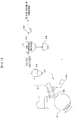
- FIG. 1 shows a cement kiln exhaust gas treatment apparatus according to the first embodiment of the present invention
- this treatment apparatus 1 roughly comprises: an extraction probe 42 for extracting a part of combustion gas from a kiln exhaust gas passage running from an inlet end of a cement kiln 41 to a bottom cyclone (not shown); a cooling fan 43 for supplying a cold air to the prove 42; a cyclone 44 as a classifier for separating a coarse powder D1 contained in a gas G1 extracted with the probe 42; a high-temperature bag filter 2 for solid/gas separating an exhaust gas G2 containing a fine powder D2 discharged from the cyclone 44; a dust tank 48 for recovering fine powder (chlorine bypass dust) collected with the high-temperature bag filter 2; an exhaust fan 49 for inducing an exhaust gas G3 from the high-temperature bag filter 2; and the like.
- devices excepting the high-temperature bag filter 2 are the same as those utilized in the conventional chlorine bypass system.
- devices in Fig. 1 are attached the same symbols as used in Fig. 5 .
- the high-temperature bag filter 2 is, for example, a bag filter with ceramic filters and is a high heat-resistance solid/gas separator with heat resistance until approximately 900°C.
- bag filters of this kind various types such as one with a plurality of stick-type ceramic tubes (ceramic filters) shaped as honeycam cells, and another with sheet-type ceramic filters are developed.
- the type of the filter will not be limited so long as it is able to collect fine particles of 0.1 ⁇ m or more from the exhaust gas G2.
- a temperature of the gas G1 extracted from the probe 42 is usually 700 °C or lower, so that from this point of view, it is unnecessary for the high-temperature bag filter 2 to have heat resistance up to 900°C, and sufficient up to 700°C .
- the exhaust gas G2 whose temperature is between 400°C and 700°C is introduced into the high-temperature bag filter 2, as described above, since the high-temperature bag filter 2 has heat resistance up to 900°C the exhaust gas G2 supplied from the cyclone 44 can be solid/gas separated with a temperature as it is. And, with the high-temperature bag filter 2, the fine powder D2 contained in the exhaust gas G2 is collected to recover it in the dust tank 48, and with the induction fan 49, the gas G3 exhausted from the high-temperature bag filter 2 is induced to return it to the cement kiln system, or after utilized as a heat source for drying cement raw materials, sludge, and the like, the gas G3 is discharged to the atmosphere.
- the installation of the high-temperature bag filter 2 downstream of the cyclone 44 allows the exhaust gas G2 to be solid/gas separated while maintaining a temperature of the gas G2 when discharged from the cyclone 44 (between 400°C and 700°C). As a result, it becomes unnecessary to cool the exhaust gas G2 during gas treatment, which makes it possible to restrain heat energy loss.
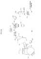
- this treatment apparatus 10 is provided with a heat exchanger 11 for cooling the exhaust gas G3 from the high-temperature bag filter 2 downstream of the high-temperature bag filter 2, and a catalyst device 12 for removing organic contaminants from an exhaust gas G5 cooled in the heat exchanger 11.
- the construction from the probe 42 to the exhaust fan 49 is the same as the treatment apparatus 1 shown in Fig. 1 .
- the heat exchanger 11 is installed to cool the exhaust gas G4 upstream of the catalyst 12 to a temperature between 150°C and 400°C, and control the temperature of the exhaust gas G4 so as to be suitable for catalyst activity.
- a conduit tube 11a for circulating heat medium this conduit tube 11a is utilized as a heat source for drying/grinding processes, boilers, and the like not shown. With this, heat recovered from the exhaust gas G4 is utilized as a heat source for drying cement raw materials or sludges.
- the catalyst device 12 is installed to decompose and remove organic contaminants contained in the exhaust gas G5.
- This catalyst device 12 can be constituted in the shape of a honeycam, so that it can be constituted comparatively small even when a large amount of exhaust gas is treated.
- the titanium-vanadium catalyst means a catalyst indispensably having titanium (Ti) and vanadium (V). This catalyst exhibits an excellent function in decomposition and removal of organic contaminants, and provides high decomposition activity of NO x (denitrogenization activity) as a toxic substance as well.
- POPs persistent organic pollutants
- PCDD dioxins
- PCDF dioxins
- co-PCB precursors of the dioxins
- PCBs polychlorinated biphenyl
- VOC volatile organic contaminants
- the exhaust gas G3 from the high-temperature bag filter 2 is introduced into the heat exchanger 11 through the exhaust fan 49. Then, in the heat exchanger 11, the exhaust gas G4 is cooled to a temperature between 150°C and 400°C while recovered heat, and then, in the catalyst device 12, organic contaminants such as POPs, VOC are decomposed to purify the exhaust gas G5. Meanwhile, an exhaust gas G6 purification-treated with the catalyst device 12 may be returned to the cement kiln system through an exhaust fan (not shown), or discharged to the atmosphere.
- the catalyst device 12 is arranged downstream of the high-temperature bag filter 2 to decompose and remove organic contaminants slightly generated and precursors of dioxins remaining in the exhaust gas, resulting in further detoxification of the exhaust gas.
- the exhaust gas G4 is introduced into the catalyst device 12 after cooled in the heat exchanger 11, depending on the kinds and the like of catalysts, there is a case where a temperature suitable for catalyst activity is approximately 500°C and the cooling is unnecessary, in such a case, it is unnecessary to install the heat exchanger 11, and the exhaust gas G3 from the high-temperature bag filter 2 may be introduced directly into the catalyst device 12.
- a spray 13 may be installed on a conduit tube 2a connecting the cyclone 44 and the high-temperature bag filter 2 with each other, and a desulfurization agent may be added if necessary.
- a desulfurization agent hydrated lime, calcium oxide, calcinated cement raw materials (cement raw materials partly withdrawn from a bottom cyclone of a preheater and the like), coal ash, sodium hydroxide or the like can be used.
- humidity control can be performed to make water content of the gas suitable for desulfurization.
- this treatment apparatus 20 is provided with a heat exchanger 21 for cooling the exhaust gas G3 from the high-temperature bag filter 2 downstream of the high-temperature bag filter 2, and an adsorption tower 22 for adsorbing and removing organic contaminants from the exhaust gas G5 cooled in the heat exchanger 21.
- the construction from the probe 42 to the exhaust fan 49 is the same as that of the treatment apparatus 1 in Fig. 1 .
- the heat exchanger 21 is installed to cool the exhaust gas G4 to a temperature between 100 °C and 200 °C upstream of the adsorption tower 22, and make the temperature of the gas G4 suitable for operation of the adsorption tower 22.
- a conduit tube 21a for circulating heat medium is connected with a dryer (not shown) and the like, heat recovered from the exhaust gas G4 is utilized as a heat resource for drying/grinding processes, a boiler, and the like.
- the adsorption tower 22 is installed to adsorb and remove organic contaminants contained in the exhaust gas G5.
- Activated carbon or the like can be utilized as an adsorbent for the organic contaminants.
- VOC volatile organic contaminants
- sulfur in the exhaust gas G5 can be removed together with POPs such as dioxins (PCDD, PCDF, co-PCB), precursors of the dioxins (former substances) and polychlorinated biphenyl (PCBs).
- PCDD dioxins
- PCDF co-PCB
- PCBs polychlorinated biphenyl
- active coke, coal, coal ash, blast-furnace ash, ash containing unburned carbon and the like are utilized as the adsorbent for the organic contaminants.
- the adsorption tower 22 installed downstream of the high-temperature bag filter 2 adsorbs and removes organic contaminants slightly generated and precursors of dioxins remaining in the exhaust gas, therefore, in the same manner as the second embodiment, it becomes possible to further effectively detoxify the exhaust gas.
- this treatment apparatus 30 is provided with a heat exchanger 31 for recovering heat from the exhaust gas G3 from the high-temperature bag filter 2 downstream of the high-temperature bag filter 2, and a recovery device 32 for recovering heavy metals from the exhaust gas G4 from which heat is recovered.
- the construction from the probe 42 to the high-temperature bag filter 2 is the same as that of the treatment apparatus 1 shown in Fig. 1 .
- the heat exchanger 31 is installed to cool the exhaust gas G4 to a temperature between 50°C and 200°C upstream of the recovery device 32, and make the temperature of the gas G4 suitable for recovering heavy metals.
- the conduit tube 31a for circulating heat medium is connected with a dryer (not shown) and the like, heat recovered from the exhaust gas G4 is utilized as a heat resource for drying/grinding processes, a boiler, and the like.
- the recovery device 32 has a dust collector, a gas-cleaning tower and a condenser.
- the dust collector is installed to collect a fine powder to which heavy metals contained in exhaust gas condense.
- the gas-cleaning tower is provided with a circulating-water conduit tube, a circulating-water pump, and the like to discharge the exhaust gas to the atmosphere, or return it to a kiln system.
- acid sulfuric acid and others
- alkali sodium hydroxide, lime milk and others
- chemicals hypoochlorous acid, chelate and others
- the exhaust gas G3 from the high-temperature bag filter 2 is introduced into the heat exchanger 31. Then, after cooled to a temperature between 50°C and 200°C in the heat exchanger 31 while heat thereof being recovered, the exhaust gas G4 is introduced into the dust collector of the recovery device 32 to collect the fine powder containing heavy metals (compounds of each heavy metal). Finally, the exhaust gas G5 is discharged to the atmosphere, or returned to the kiln system.
- the heat exchanger 31 is arranged between the high-temperature bag filter 2 and the recovery device 32, without equipping the heat exchanger 31, it is also possible to recover heavy metals by using a recovery device capable of recovering volatilizing heavy metals in the exhaust gas as they are.
- selenium, thallium, zinc, antimony, tellurium, mercury, and arsenic are mentioned as heavy metals in the above embodiment, especially, selenium and thallium, which have low melting points and easily vaporize in the exhaust gas, are efficiently recoverable in these metals.
- spraying a heavy metals elusion inhibitor such as lime and activated carbon to the exhaust gas before introducing the exhaust gas into the dust collector of the recovery device 32 prevents heavy metals from eluting from the fine powder where the heavy metals condense.
- the heat exchanger 31 is utilized to cool the exhaust gas G3, but it is also possible to perform cooling only with a cooler without recovering heat from the exhaust gas G3. And, introducing cold air into the exhaust gas G3 is also able to control the gas temperature.
- the exhaust gas G2 containing the fine powder D2 is introduced into the high-temperature bag filter 2, but the gas G1 extracted with the probe 42 may be introduced directly into the high-temperature bag filter 2 without installing the cyclone 44.
- a part of combustion gas from the inlet end of the cement kiln 41 is extracted with the probe 42, instead of the inlet end, a part of combustion gas can be extracted from a kiln exhaust gas passage running from the inlet end to the bottom cyclone.
Landscapes
- Engineering & Computer Science (AREA)
- Chemical & Material Sciences (AREA)
- Environmental & Geological Engineering (AREA)
- Chemical Kinetics & Catalysis (AREA)
- Health & Medical Sciences (AREA)
- Oil, Petroleum & Natural Gas (AREA)
- Analytical Chemistry (AREA)
- General Chemical & Material Sciences (AREA)
- Biomedical Technology (AREA)
- General Engineering & Computer Science (AREA)
- Mechanical Engineering (AREA)
- Ceramic Engineering (AREA)
- Life Sciences & Earth Sciences (AREA)
- Biodiversity & Conservation Biology (AREA)
- Environmental Sciences (AREA)
- Public Health (AREA)
- Ecology (AREA)
- Materials Engineering (AREA)
- Structural Engineering (AREA)
- Organic Chemistry (AREA)
- Treating Waste Gases (AREA)
- Processing Of Solid Wastes (AREA)
- Inorganic Chemistry (AREA)
- Geology (AREA)
Applications Claiming Priority (3)
| Application Number | Priority Date | Filing Date | Title |
|---|---|---|---|
| JP2008157792 | 2008-06-17 | ||
| JP2008294245 | 2008-11-18 | ||
| PCT/JP2009/060338 WO2009154088A1 (ja) | 2008-06-17 | 2009-06-05 | セメントキルン排ガスの処理装置及び処理方法 |
Publications (2)
| Publication Number | Publication Date |
|---|---|
| EP2287126A1 true EP2287126A1 (de) | 2011-02-23 |
| EP2287126A4 EP2287126A4 (de) | 2014-03-26 |
Family
ID=41434004
Family Applications (1)
| Application Number | Title | Priority Date | Filing Date |
|---|---|---|---|
| EP09766536.8A Withdrawn EP2287126A4 (de) | 2008-06-17 | 2009-06-05 | Vorrichtung und verfahren zur verarbeitung von gas aus einem zementofen |
Country Status (6)
| Country | Link |
|---|---|
| EP (1) | EP2287126A4 (de) |
| JP (1) | JP5522740B2 (de) |
| KR (2) | KR101721614B1 (de) |
| CN (2) | CN104964573A (de) |
| TW (1) | TW201002413A (de) |
| WO (1) | WO2009154088A1 (de) |
Cited By (9)
| Publication number | Priority date | Publication date | Assignee | Title |
|---|---|---|---|---|
| EP2389997A4 (de) * | 2009-01-22 | 2012-10-31 | Taiheiyo Cement Corp | Vorrichtung zum entfernen von schwermetallen und zementherstellungssystem |
| EP2604586A4 (de) * | 2010-08-10 | 2015-04-22 | Taiheiyo Cement Corp | Verfahren und vorrichtung zur bearbeitung von chlor-bypassstaub und entladungsgas |
| WO2015067363A1 (de) * | 2013-11-06 | 2015-05-14 | Thyssenkrupp Industrial Solutions Ag | Verfahren zur reinigung von bypassgasen der zement- oder mineralsindustrie sowie anlage der zement- oder mineralsindustrie |
| AT14170U1 (de) * | 2014-05-27 | 2015-05-15 | Scheuch Gmbh | Vorrichtung zur Herstellung von Zementklinker |
| WO2016001409A1 (de) * | 2014-07-03 | 2016-01-07 | Thyssenkrupp Industrial Solutions Ag | Adsorption von voc an flugasche und bodenprodukt aus vergasungsprozessen |
| EP2992942A1 (de) * | 2014-09-03 | 2016-03-09 | SLM Solutions Group AG | Vorrichtung zur Herstellung von 3D Werkstücken durch schichtweises Aufbauen mit verbessertem Recyclinggaskreislauf |
| WO2016139225A1 (de) * | 2015-03-04 | 2016-09-09 | Khd Humboldt Wedag Gmbh | Verfahren und anlage zur entstickung von bypassgasen in einem mehrstufigen system von mischkammern bei einer anlage zur herstellung von zementklinker |
| WO2019072957A1 (de) * | 2017-10-12 | 2019-04-18 | Thyssenkrupp Industrial Solutions Ag | Verfahren und anlage zur herstellung von zementklinker oder eines anderen mineralischen produkts |
| EP3055266B1 (de) | 2013-10-08 | 2019-08-21 | KHD Humboldt Wedag GmbH | Verfahren zur entstickung von bypassabgasen in einer anlage zur herstellung von zementklinker |
Families Citing this family (22)
| Publication number | Priority date | Publication date | Assignee | Title |
|---|---|---|---|---|
| JP5501694B2 (ja) * | 2009-08-19 | 2014-05-28 | 太平洋セメント株式会社 | 肥料並びにその製造方法及び製造装置 |
| TWI586923B (zh) * | 2010-02-23 | 2017-06-11 | 太平洋水泥股份有限公司 | 焚化灰燼及水泥窯燃燒氣體抽氣粉塵之水洗方法以及水洗系統 |
| US8377175B2 (en) | 2010-02-26 | 2013-02-19 | Arcelormittal Investigacion Y Desarrollo, S.L. | Apparatus and method for treating exhaust gas |
| ES2612484T3 (es) * | 2010-02-26 | 2017-05-17 | Arcelormittal | Aparato y procedimiento para el tratamiento de gases de escape que contienen vapores de zinc |
| JP5348792B2 (ja) * | 2010-03-17 | 2013-11-20 | 太平洋セメント株式会社 | 燃焼ガス抽気プローブ及びその運転方法 |
| JP5652950B2 (ja) * | 2011-01-06 | 2015-01-14 | 太平洋セメント株式会社 | 塩素バイパスシステム及び塩素バイパス抽気ガスの処理方法 |
| CN106524773A (zh) * | 2011-01-31 | 2017-03-22 | 太平洋水泥株式会社 | 氯旁通系统和氯旁通抽气气体的处理方法 |
| JP2012188322A (ja) * | 2011-03-11 | 2012-10-04 | Taiheiyo Cement Corp | 塩素バイパス排ガスの処理装置及び処理方法 |
| JP2012200627A (ja) * | 2011-03-24 | 2012-10-22 | Taiheiyo Cement Corp | 塩素バイパス排ガスの処理装置及び処理方法 |
| JP5850494B2 (ja) * | 2011-11-18 | 2016-02-03 | 太平洋セメント株式会社 | 放射性セシウムの除去方法及び除去装置 |
| DE102012110653B3 (de) * | 2012-11-07 | 2014-05-15 | Thyssenkrupp Resource Technologies Gmbh | Zementherstellungsanlage |
| JP6046526B2 (ja) * | 2013-03-11 | 2016-12-14 | 日本山村硝子株式会社 | 排ガス中のセレン回収システムおよびセレン回収方法 |
| JP2016056070A (ja) * | 2014-09-11 | 2016-04-21 | 太平洋セメント株式会社 | 塩素バイパス排ガスの処理方法 |
| CN109045965B (zh) * | 2018-09-03 | 2024-05-31 | 环境保护部华南环境科学研究所 | 一种废气净化系统及方法 |
| JP7352867B2 (ja) * | 2020-03-23 | 2023-09-29 | 住友大阪セメント株式会社 | 塩素バイパスダストの処理方法、セメント混和材の製造方法、セメント組成物の製造方法、セメント硬化体の製造方法、塩素バイパスダストの処理装置、および、セメント混和材の製造装置 |
| CN112275036B (zh) * | 2020-10-14 | 2022-06-17 | 太仓中化环保化工有限公司 | 一种用于制冷剂生产过程汇总副产物分离设备 |
| CN112807873A (zh) * | 2020-12-22 | 2021-05-18 | 佛山市伊清环保工程技术有限公司 | 一种窑炉烟气多污染物协同治理成套装备 |
| KR102297744B1 (ko) * | 2021-03-02 | 2021-09-02 | 허주영 | 시멘트 소성로 또는 제철소 소결로 공정에서 탈질 및 디더스팅(De-Dusting) 기능을 동시 처리하는 촉매 일체형 집진기 |
| JP2022139866A (ja) * | 2021-03-12 | 2022-09-26 | Ube三菱セメント株式会社 | セメントクリンカ及びセメントの製造方法 |
| CN113181737B (zh) * | 2021-06-15 | 2024-10-25 | 玉锋实业集团有限公司 | 一种带有袋滤器的淀粉干燥除尘装置 |
| TWI786954B (zh) | 2021-11-22 | 2022-12-11 | 財團法人工業技術研究院 | 同時去除易燃氣體與一氧化二氮的裝置與方法 |
| KR102512130B1 (ko) | 2022-10-24 | 2023-03-22 | 쌍용씨앤이 주식회사 | 시멘트 소성로의 순환물질을 인출하여 배가스 오염물질을 처리하는 장치 및 방법 |
Family Cites Families (17)
| Publication number | Priority date | Publication date | Assignee | Title |
|---|---|---|---|---|
| DK0808809T4 (da) * | 1995-12-11 | 2012-12-10 | Taiheiyo Cement Corp | Fremgangsmåde til behandling af ovnforbrændingsgas ved afledning af chlor og et apparat dertil |
| JPH09227184A (ja) * | 1996-02-21 | 1997-09-02 | Chichibu Onoda Cement Corp | セメントキルン排ガス処理方法及びその装置 |
| JP3172131B2 (ja) * | 1997-10-24 | 2001-06-04 | 川崎重工業株式会社 | セメント焼成装置からの有害物質の除去方法及び装置 |
| WO2000012444A1 (fr) * | 1998-08-28 | 2000-03-09 | Taiheiyo Cement Corporation | Dispositif et procede de derivation des gaz brules d'un four |
| JP4418055B2 (ja) * | 1999-08-31 | 2010-02-17 | 太平洋セメント株式会社 | アルカリ塩化物の分離方法及び装置 |
| JP2002166125A (ja) * | 2000-11-29 | 2002-06-11 | Taiheiyo Cement Corp | 燃焼排ガスの処理方法 |
| JP2003117343A (ja) * | 2001-10-12 | 2003-04-22 | Mitsubishi Heavy Ind Ltd | 排ガス処理装置 |
| JP2003277106A (ja) * | 2002-03-27 | 2003-10-02 | Taiheiyo Cement Corp | 排ガス処理方法及び処理装置 |
| JP3933509B2 (ja) * | 2002-03-29 | 2007-06-20 | 太平洋セメント株式会社 | 塩化カリウムの回収方法及び回収装置 |
| EP1649922B1 (de) * | 2003-07-10 | 2011-01-26 | Taiheiyo Cement Corporation | Vorrichtung und verfahren zur behandlung von verbrennungsabgas |
| CN100455532C (zh) * | 2004-09-29 | 2009-01-28 | 太平洋水泥株式会社 | 水泥窑燃烧气体抽气灰尘的处理系统及处理方法 |
| JP2006096615A (ja) * | 2004-09-29 | 2006-04-13 | Taiheiyo Cement Corp | セメントキルンの排ガスの処理方法 |
| EP1842836A4 (de) * | 2005-01-06 | 2013-12-11 | Taiheiyo Cement Corp | Vorrichtung und verfahren zur verarbeitung von zementofenverbrennungsabgas |
| JP4823596B2 (ja) * | 2005-07-25 | 2011-11-24 | 住友大阪セメント株式会社 | セメント焼成設備における排ガスの処理方法及び処理装置 |
| JP4689514B2 (ja) * | 2006-03-29 | 2011-05-25 | 住友大阪セメント株式会社 | セメント焼成設備における排ガスの処理方法及び処理装置 |
| JP5088923B2 (ja) * | 2006-07-19 | 2012-12-05 | 太平洋セメント株式会社 | セメント製造方法及び装置 |
| JP2008132413A (ja) | 2006-11-28 | 2008-06-12 | Taiheiyo Cement Corp | 燃焼排ガス処理装置及び湿式集塵機排水処理方法 |
-
2009
- 2009-06-05 KR KR1020157034289A patent/KR101721614B1/ko active Active
- 2009-06-05 TW TW098118760A patent/TW201002413A/zh unknown
- 2009-06-05 CN CN201510449548.9A patent/CN104964573A/zh active Pending
- 2009-06-05 JP JP2010517844A patent/JP5522740B2/ja active Active
- 2009-06-05 EP EP09766536.8A patent/EP2287126A4/de not_active Withdrawn
- 2009-06-05 CN CN2009801230756A patent/CN102066282A/zh active Pending
- 2009-06-05 WO PCT/JP2009/060338 patent/WO2009154088A1/ja not_active Ceased
- 2009-06-05 KR KR1020107027486A patent/KR20110030446A/ko not_active Ceased
Cited By (16)
| Publication number | Priority date | Publication date | Assignee | Title |
|---|---|---|---|---|
| US8679234B2 (en) | 2009-01-22 | 2014-03-25 | Taiheiyo Cement Corporation | Heavy metal removing apparatus and cement production system |
| EP2389997A4 (de) * | 2009-01-22 | 2012-10-31 | Taiheiyo Cement Corp | Vorrichtung zum entfernen von schwermetallen und zementherstellungssystem |
| EP2604586A4 (de) * | 2010-08-10 | 2015-04-22 | Taiheiyo Cement Corp | Verfahren und vorrichtung zur bearbeitung von chlor-bypassstaub und entladungsgas |
| EP3055266B1 (de) | 2013-10-08 | 2019-08-21 | KHD Humboldt Wedag GmbH | Verfahren zur entstickung von bypassabgasen in einer anlage zur herstellung von zementklinker |
| CN105705218A (zh) * | 2013-11-06 | 2016-06-22 | 蒂森克虏伯工业解决方案股份公司 | 用于清洁水泥或矿产业的旁路气体的方法以及水泥或矿产业的系统 |
| WO2015067363A1 (de) * | 2013-11-06 | 2015-05-14 | Thyssenkrupp Industrial Solutions Ag | Verfahren zur reinigung von bypassgasen der zement- oder mineralsindustrie sowie anlage der zement- oder mineralsindustrie |
| US9855527B2 (en) | 2013-11-06 | 2018-01-02 | Thyssenkrupp Industrial Solutions Ag | Method for cleaning bypass gases of the cement or mineral industry, and system of the cement or mineral industry |
| AT14170U1 (de) * | 2014-05-27 | 2015-05-15 | Scheuch Gmbh | Vorrichtung zur Herstellung von Zementklinker |
| WO2015179892A1 (de) | 2014-05-27 | 2015-12-03 | Scheuch Gmbh | Vorrichtung zur herstellung von zementklinker |
| WO2016001409A1 (de) * | 2014-07-03 | 2016-01-07 | Thyssenkrupp Industrial Solutions Ag | Adsorption von voc an flugasche und bodenprodukt aus vergasungsprozessen |
| EP2992942A1 (de) * | 2014-09-03 | 2016-03-09 | SLM Solutions Group AG | Vorrichtung zur Herstellung von 3D Werkstücken durch schichtweises Aufbauen mit verbessertem Recyclinggaskreislauf |
| WO2016139225A1 (de) * | 2015-03-04 | 2016-09-09 | Khd Humboldt Wedag Gmbh | Verfahren und anlage zur entstickung von bypassgasen in einem mehrstufigen system von mischkammern bei einer anlage zur herstellung von zementklinker |
| CN107428610A (zh) * | 2015-03-04 | 2017-12-01 | Khd洪保德韦达克有限公司 | 在生产水泥熟料的装置中、于混合室的多阶段系统中用于使旁通气体脱氮的方法和装置 |
| US10260809B2 (en) | 2015-03-04 | 2019-04-16 | Khd Humboldt Wedag Gmbh | Method and plant for denitrifying bypass gases in a multi-stage system of mixing chambers in a plant for producing cement clinker |
| US20190154335A1 (en) * | 2015-03-04 | 2019-05-23 | Khd Humboldt Wedag Gmbh | Method and plant for denitrifying bypass gases in a multi-stage system of mixing chambers in a plant for producing cement clinker |
| WO2019072957A1 (de) * | 2017-10-12 | 2019-04-18 | Thyssenkrupp Industrial Solutions Ag | Verfahren und anlage zur herstellung von zementklinker oder eines anderen mineralischen produkts |
Also Published As
| Publication number | Publication date |
|---|---|
| JP5522740B2 (ja) | 2014-06-18 |
| JPWO2009154088A1 (ja) | 2011-11-24 |
| CN102066282A (zh) | 2011-05-18 |
| EP2287126A4 (de) | 2014-03-26 |
| TW201002413A (en) | 2010-01-16 |
| KR20150140870A (ko) | 2015-12-16 |
| CN104964573A (zh) | 2015-10-07 |
| KR101721614B1 (ko) | 2017-03-30 |
| KR20110030446A (ko) | 2011-03-23 |
| WO2009154088A1 (ja) | 2009-12-23 |
Similar Documents
| Publication | Publication Date | Title |
|---|---|---|
| EP2287126A1 (de) | Vorrichtung und verfahren zur verarbeitung von gas aus einem zementofen | |
| EP1649922B1 (de) | Vorrichtung und verfahren zur behandlung von verbrennungsabgas | |
| KR101425289B1 (ko) | 배기가스 처리 시스템 및 배기가스 처리 방법 | |
| JP5877578B2 (ja) | 燃焼排ガス処理装置及び処理方法 | |
| JPWO2009110356A1 (ja) | セメントキルン抽気ガスの処理システム及び処理方法 | |
| KR20120080222A (ko) | 배기 가스 처리 시스템 및 배기 가스 처리 방법 | |
| JP5917190B2 (ja) | 排ガス中の水銀回収装置 | |
| JP2013248548A (ja) | 排ガス処理方法および排ガス処理装置 | |
| US4873065A (en) | Flue gas purification process | |
| JPH10109016A (ja) | 重金属含有排ガス処理方法と装置 | |
| JP5867690B2 (ja) | 排ガス処理システムと排ガス処理方法 | |
| JP2007039296A (ja) | セメント製造装置の排ガスの処理方法及び処理システム | |
| JP2015213858A (ja) | セメントキルンの燃焼排ガス処理装置及び処理方法 | |
| JP5808072B2 (ja) | セメントキルン抽気ガスの処理システム及び処理方法 | |
| JP5823269B2 (ja) | セメントキルン排ガスの処理システム及びその運転方法 | |
| JP2007117890A (ja) | 排ガス処理方法及びシステム | |
| JP5528743B2 (ja) | セメントキルン抽気ガスの処理システム及び処理方法 | |
| HK1153725A (en) | Apparatus and method for treating gas discharged from cement kiln | |
| JP4781005B2 (ja) | 湿式集塵機排水処理方法 | |
| HK1196581A (en) | System and method for treating bleed gas from cement kiln | |
| HK1148265A (en) | System and method for treating bleed gas from cement kiln | |
| JPH0533089B2 (de) | ||
| JP2007216183A (ja) | ダイオキシン類の除去方法 |
Legal Events
| Date | Code | Title | Description |
|---|---|---|---|
| PUAI | Public reference made under article 153(3) epc to a published international application that has entered the european phase |
Free format text: ORIGINAL CODE: 0009012 |
|
| 17P | Request for examination filed |
Effective date: 20101117 |
|
| AK | Designated contracting states |
Kind code of ref document: A1 Designated state(s): AT BE BG CH CY CZ DE DK EE ES FI FR GB GR HR HU IE IS IT LI LT LU LV MC MK MT NL NO PL PT RO SE SI SK TR |
|
| AX | Request for extension of the european patent |
Extension state: AL BA RS |
|
| DAX | Request for extension of the european patent (deleted) | ||
| A4 | Supplementary search report drawn up and despatched |
Effective date: 20140226 |
|
| RIC1 | Information provided on ipc code assigned before grant |
Ipc: B01D 53/94 20060101ALI20140220BHEP Ipc: B01D 53/81 20060101ALI20140220BHEP Ipc: C04B 7/60 20060101AFI20140220BHEP Ipc: B01D 53/86 20060101ALI20140220BHEP Ipc: B01D 53/72 20060101ALI20140220BHEP Ipc: F27D 17/00 20060101ALI20140220BHEP Ipc: C04B 7/36 20060101ALI20140220BHEP Ipc: F27B 7/42 20060101ALI20140220BHEP Ipc: B01D 53/50 20060101ALI20140220BHEP Ipc: B01D 53/75 20060101ALI20140220BHEP Ipc: B01D 53/70 20060101ALI20140220BHEP |
|
| STAA | Information on the status of an ep patent application or granted ep patent |
Free format text: STATUS: THE APPLICATION IS DEEMED TO BE WITHDRAWN |
|
| 18D | Application deemed to be withdrawn |
Effective date: 20140925 |