EP2287400A2 - Schienenunterstützungs-Anordnung mit federnden Befestigungselementen - Google Patents
Schienenunterstützungs-Anordnung mit federnden Befestigungselementen Download PDFInfo
- Publication number
- EP2287400A2 EP2287400A2 EP10171911A EP10171911A EP2287400A2 EP 2287400 A2 EP2287400 A2 EP 2287400A2 EP 10171911 A EP10171911 A EP 10171911A EP 10171911 A EP10171911 A EP 10171911A EP 2287400 A2 EP2287400 A2 EP 2287400A2
- Authority
- EP
- European Patent Office
- Prior art keywords
- slabs
- rails
- slab
- ground
- assembly according
- Prior art date
- Legal status (The legal status is an assumption and is not a legal conclusion. Google has not performed a legal analysis and makes no representation as to the accuracy of the status listed.)
- Withdrawn
Links
- 239000004567 concrete Substances 0.000 claims description 9
- 239000002184 metal Substances 0.000 claims description 9
- 239000013013 elastic material Substances 0.000 claims description 5
- 239000004570 mortar (masonry) Substances 0.000 claims description 5
- 238000007667 floating Methods 0.000 claims description 2
- 230000002093 peripheral effect Effects 0.000 claims 2
- 230000003014 reinforcing effect Effects 0.000 claims 1
- 230000010355 oscillation Effects 0.000 description 6
- 230000005540 biological transmission Effects 0.000 description 4
- 239000011150 reinforced concrete Substances 0.000 description 4
- 239000004568 cement Substances 0.000 description 3
- 230000000284 resting effect Effects 0.000 description 3
- 230000009471 action Effects 0.000 description 2
- 230000000712 assembly Effects 0.000 description 2
- 238000000429 assembly Methods 0.000 description 2
- 238000009412 basement excavation Methods 0.000 description 2
- 230000008901 benefit Effects 0.000 description 2
- 238000010276 construction Methods 0.000 description 2
- 239000007788 liquid Substances 0.000 description 2
- 238000012423 maintenance Methods 0.000 description 2
- 239000000463 material Substances 0.000 description 2
- 230000002787 reinforcement Effects 0.000 description 2
- XLYOFNOQVPJJNP-UHFFFAOYSA-N water Substances O XLYOFNOQVPJJNP-UHFFFAOYSA-N 0.000 description 2
- 241001669679 Eleotris Species 0.000 description 1
- 230000002238 attenuated effect Effects 0.000 description 1
- 238000005266 casting Methods 0.000 description 1
- 230000008878 coupling Effects 0.000 description 1
- 238000010168 coupling process Methods 0.000 description 1
- 238000005859 coupling reaction Methods 0.000 description 1
- 230000001419 dependent effect Effects 0.000 description 1
- 238000006073 displacement reaction Methods 0.000 description 1
- 230000000670 limiting effect Effects 0.000 description 1
- 238000000034 method Methods 0.000 description 1
- 238000012986 modification Methods 0.000 description 1
- 230000004048 modification Effects 0.000 description 1
- 230000036961 partial effect Effects 0.000 description 1
- 230000002829 reductive effect Effects 0.000 description 1
- 239000007787 solid Substances 0.000 description 1
- 125000006850 spacer group Chemical group 0.000 description 1
- 238000004804 winding Methods 0.000 description 1
- 239000002023 wood Substances 0.000 description 1
Images



Classifications
-
- E—FIXED CONSTRUCTIONS
- E01—CONSTRUCTION OF ROADS, RAILWAYS, OR BRIDGES
- E01B—PERMANENT WAY; PERMANENT-WAY TOOLS; MACHINES FOR MAKING RAILWAYS OF ALL KINDS
- E01B1/00—Ballastway; Other means for supporting the sleepers or the track; Drainage of the ballastway
- E01B1/002—Ballastless track, e.g. concrete slab trackway, or with asphalt layers
- E01B1/007—Ballastless track, e.g. concrete slab trackway, or with asphalt layers with interlocking means to withstand horizontal forces
-
- E—FIXED CONSTRUCTIONS
- E01—CONSTRUCTION OF ROADS, RAILWAYS, OR BRIDGES
- E01B—PERMANENT WAY; PERMANENT-WAY TOOLS; MACHINES FOR MAKING RAILWAYS OF ALL KINDS
- E01B19/00—Protection of permanent way against development of dust or against the effect of wind, sun, frost, or corrosion; Means to reduce development of noise
- E01B19/003—Means for reducing the development or propagation of noise
-
- E—FIXED CONSTRUCTIONS
- E01—CONSTRUCTION OF ROADS, RAILWAYS, OR BRIDGES
- E01B—PERMANENT WAY; PERMANENT-WAY TOOLS; MACHINES FOR MAKING RAILWAYS OF ALL KINDS
- E01B2/00—General structure of permanent way
- E01B2/003—Arrangement of tracks on bridges or in tunnels
-
- E—FIXED CONSTRUCTIONS
- E01—CONSTRUCTION OF ROADS, RAILWAYS, OR BRIDGES
- E01B—PERMANENT WAY; PERMANENT-WAY TOOLS; MACHINES FOR MAKING RAILWAYS OF ALL KINDS
- E01B3/00—Transverse or longitudinal sleepers; Other means resting directly on the ballastway for supporting rails
- E01B3/28—Transverse or longitudinal sleepers; Other means resting directly on the ballastway for supporting rails made from concrete or from natural or artificial stone
- E01B3/40—Slabs; Blocks; Pot sleepers; Fastening tie-rods to them
Definitions
- the present invention refers to a rail supporting assembly comprising slabs with cushioning elements for fastening thereof to the ground.
- further cushioning elements may be interposed, underneath and to the sides, between the rail supporing elements and their seats (apertures) formed in said slabs.
- the main object of the present invention is, therefore, to overcome the above mentioned drawbacks of the prior art, by providing a supporting assembly for railway and/or subway lines made up of slabs having a reduced transmission of stresses to the ground and improved cushioning of vibrations, even those due to lateral or transverse oscillations of the slabs during the passage of carriages on the rails.
- a further object of the present invention is that of providing such an assembly that leaves escape routes free, and that does not require wider and thus more costly tunnels to be created.
- Said fastening elements are able to stop longitudinal and/or transverse movements (displacements) of the slabs with respect to the ground, preventing them from shifting with respect to their seat but without impairing their ability to balance (float) in said resting position.
- Each of said fastening elements is formed by a parallelepiped-shaped rigid central structure fixed to the ground (seat) and an outer rubber part (frame) which laterally surrounds said inner structure and in which each fixing element is housed in a cavity suitably formed in said slabs so that each cavity is a through cavity passing through the thickness of said slabs.
- Each cavity is preferably formed by two recesses of two adjacent slabs made on the sides of each slab perpendicularly to the direction of movement (longitudinal axis of the rails).
- each cavity as defined above may be replaced by a through cavity formed completely inside said slabs; or each cavity as defined above may be replaced by a plurality of cavities formed between adjacent slabs or formed completely inside each of said slabs.
- each of said cavities as defined above may be open at the bottom towards the ground but closed at the top towards the rails.
- the central part of the fastening element acts as a stopper against movements of the slab in the direction of movement of the train and transversally to said movement whilst the external rubber part which surrounds the central structure acts as a cushioning element for the vibrations generated by lateral oscillations of the slab both in the direction of movement of the train and transversally to said movement.
- the fastening element or stopper is in contact with the slabs through its elastic frame (outer cushioning rubber) and is fastened to the ground by means of tie bars: there are no other tie bars that fix the slab to the ground so that no tie bars pass through the slab.
- the number of fastening elements is not binding for the purposes of the present invention.
- the rails keep the slabs bound to each other, one might think of using a smaller number of the above described cushioning fastening elements than the number of slabs, for example providing for there to be two or more, preferably three, slabs between two fastening elements.
- stopper every so often (for example one out of ten or even twenty) to allow water to drain easily into the manholes beneath.
- slab is any block of reinforced concrete on which one or more rail contact and constraining assemblies must be housed. Said blocks of reinforced concrete are constrained to each other by means of the rails which pass from one block to another.
- rail supporting (or bearing) elements is any element on which a rail may be rested and able also to carry the members for fastening of said rail to said element.
- These elements may be blocks, sleepers or couplers for rails formed directly with the slab by concrete casting, preferably sleepers, commonly used in the railway and subway field.
- the sleepers may be standard railway sleepers, of wood, French type twin-block, etc.
- said slab is generally in the form of a parallelepiped whose dimensions depend upon the characteristics and the type of railway or subway line that is to be built, the dimensions of the fastening element remaining equal.
- shape of the slab also depends upon the type of supporting element that is chosen in creating the line which will be housed in one or more apertures specially formed in the slab.
- cushioning elastic elements are also provided, interposed between the seat of the railway structure represented by the excavation in the ground (also known as the slab) and the cement slabs, over which the present slab assembly floats.
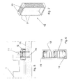
- FIG 1 shows diagrammatically part of an assembly 100 for supporting and fastening to the ground rails of railway and/or subway lines 21, with vibration cushioning, of the present invention, represented for simplicity of the drawing by three slabs (defined also as plates), each designated by the reference numeral 1 and including sleepers 20.
- Reference numeral 11 indicates a fastening element which is placed between one slab 1 and the other ( Figure 2 ). Beneath each slab 1 there are positioned elastic cushioning elements 9 which in turn rest on the seat 10 of the assembly ( Figure 3a ).
- each slab can float in its resting position.
- the seat 10 is created after having carried out the excavation, housed suitable pipes, for example for drainage of rain water, and after having performed compacting operations so as to provide a highly coplanar plane, as illustrated in Figure 3a .
- FIG 3 shows diagrammatically the part of the assembly 100 illustrated in Figures 1-2 but without sleepers 20 (or ties) and rails 21 and without some fastening elements 11 (those adjacent to two slabs 1) for the sake of simplicity of the drawing.
- Each of said slabs 1 has a plurality of three housings 2 able to accommodate the sleepers 20 ( Figure 1 ).
- Each slab 1 further has two C-shaped undercuts 4 cut in the sides 5 perpendicular to the axes 3 of the rails. When two slabs 1 come to be in a position adjacent to one another, the respective C-shaped undercuts 4 form a rectangular cavity 8. Said cavity 8 passes through the thickness of the slabs 1.
- the fastening element 11 is housed in one or more of said cavities 8 formed by adjacent slabs 1. Said fastening element 11 is only in contact with the undercuts 4 of the slabs as shown in Figure 3 .
- said fastening element 11 or stopper is in contact with the slabs through its elastic frame (outer cushioning rubber) and is fastened to the ground by means of tie bars.
- rubber or elastic elements 34 can be inserted between the sleepers 20 and their seat in the slab 1 ( Figure 8 ) in order further to reduce vibrations.
- Said elements 34 are generally glued around the ends of the sleepers 20 and subsequently said sleepers are laid in the respective housing 2.
- Said fastening element 11 is formed by an outer rectangular frame 12 made of cushioning elastic material, for example rubber, and the outer profile thereof equal to the size of the cavity 8 formed by the undercuts 4 of two adjacent slabs 1. Any cushioning material used in the art to reduce and/or cushion mechanical stresses and the transmission of vibrations can be used as cushioning elastic material.
- the thickness of the frame 12 can advantageously range from 20 to 200 mm, for example. In a preferred embodiment the thickness is 40 mm.
- such an assembly is also advantageous compared with assemblies used for non-subway lines wherein the slabs rest on an underlying concrete slab thanks to the presence of protruding parts suitable to be fixed in the slabs beneath, provided with non through cavities, by means of a groove-and-tongue coupling, so as to obtain fixing of the slab.
- this embodiment entails long maintenance operations in view of the need to lift the slab to gain access to the underlying concrete slab.
Landscapes
- Engineering & Computer Science (AREA)
- Architecture (AREA)
- Civil Engineering (AREA)
- Structural Engineering (AREA)
- Railway Tracks (AREA)
- Machines For Laying And Maintaining Railways (AREA)
- Fluid-Damping Devices (AREA)
- Vibration Dampers (AREA)
- Road Paving Structures (AREA)
Applications Claiming Priority (1)
| Application Number | Priority Date | Filing Date | Title |
|---|---|---|---|
| IT001435A ITMI20091435A1 (it) | 2009-08-06 | 2009-08-06 | Sistema di supporto di rotaie con elementi di fissaggio ammortizzanti |
Publications (2)
| Publication Number | Publication Date |
|---|---|
| EP2287400A2 true EP2287400A2 (de) | 2011-02-23 |
| EP2287400A3 EP2287400A3 (de) | 2013-10-09 |
Family
ID=41666713
Family Applications (1)
| Application Number | Title | Priority Date | Filing Date |
|---|---|---|---|
| EP10171911.0A Withdrawn EP2287400A3 (de) | 2009-08-06 | 2010-08-04 | Schienenunterstützungs-Anordnung mit federnden Befestigungselementen |
Country Status (2)
| Country | Link |
|---|---|
| EP (1) | EP2287400A3 (de) |
| IT (1) | ITMI20091435A1 (de) |
Cited By (5)
| Publication number | Priority date | Publication date | Assignee | Title |
|---|---|---|---|---|
| WO2016129001A1 (en) * | 2015-02-10 | 2016-08-18 | Vianini Industria S.P.A. | Modular system for the laying of underground and railroad and tram lines |
| CN107858872A (zh) * | 2017-12-25 | 2018-03-30 | 洛阳明创矿山冶金设备有限公司 | 一种可实现自动预紧的地铁导轨结构 |
| WO2022153046A1 (en) * | 2021-01-12 | 2022-07-21 | The Council Of The City Of Coventry | Rail support arrangement |
| CN115522412A (zh) * | 2022-11-28 | 2022-12-27 | 无锡市青山铁路器材有限公司 | 一种铁路轨道减振组件系统 |
| CN115821644A (zh) * | 2022-10-27 | 2023-03-21 | 武汉理工大学 | 无砟轨道、板、轨道板部及承轨部 |
Family Cites Families (6)
| Publication number | Priority date | Publication date | Assignee | Title |
|---|---|---|---|---|
| FR2204198A5 (de) * | 1972-10-24 | 1974-05-17 | Bernard Raoul | |
| DE4415363C1 (de) * | 1994-05-02 | 1995-09-28 | Walter Bau Ag | Eine feste Fahrbahn bildender Oberbau für Schienenbahnen, insb. für Brücken und Verfahren zu seiner Herstellung |
| DE19620731A1 (de) * | 1996-05-23 | 1997-11-27 | Strabag Hoch Und Ingenieurbau | Feste Fahrbahn für schienengebundene Fahrzeuge auf Brücken und Verfahren zu ihrer Herstellung |
| IT1296837B1 (it) * | 1997-12-03 | 1999-08-02 | Mario Ernesto Santini | Struttura per il sostegno ed il contenimento di campate di binario ferroviario e procedimento per la posa in opera della suddetta |
| DE10018112A1 (de) * | 2000-04-12 | 2001-10-25 | Zueblin Ag | Verfahren zur Herstellung einer schwingungsgedämpften festen Fahrbahn auf Tunneln, Brücken oder in Trögen |
| DE50209523D1 (de) * | 2001-09-04 | 2007-04-05 | Rail One Gmbh | Feste Fahrbahn mit zumindest einer Monoblockschwelle |
-
2009
- 2009-08-06 IT IT001435A patent/ITMI20091435A1/it unknown
-
2010
- 2010-08-04 EP EP10171911.0A patent/EP2287400A3/de not_active Withdrawn
Non-Patent Citations (1)
| Title |
|---|
| None |
Cited By (10)
| Publication number | Priority date | Publication date | Assignee | Title |
|---|---|---|---|---|
| WO2016129001A1 (en) * | 2015-02-10 | 2016-08-18 | Vianini Industria S.P.A. | Modular system for the laying of underground and railroad and tram lines |
| CN107858872A (zh) * | 2017-12-25 | 2018-03-30 | 洛阳明创矿山冶金设备有限公司 | 一种可实现自动预紧的地铁导轨结构 |
| WO2022153046A1 (en) * | 2021-01-12 | 2022-07-21 | The Council Of The City Of Coventry | Rail support arrangement |
| WO2022153049A1 (en) * | 2021-01-12 | 2022-07-21 | The Council Of The City Of Coventry | Method of installing a rail support arrangement |
| GB2618743A (en) * | 2021-01-12 | 2023-11-15 | The Council Of The City Of Coventry | Method of installing a rail support arrangement |
| GB2621708A (en) * | 2021-01-12 | 2024-02-21 | The Council Of The City Of Coventry | Rail support arrangement |
| GB2618743B (en) * | 2021-01-12 | 2024-06-05 | The Council Of The City Of Coventry | Railway Infrastructure For A Rail System |
| GB2621708B (en) * | 2021-01-12 | 2024-10-16 | The Council Of The City Of Coventry | Railway Infrastructure for a Light Rail System |
| CN115821644A (zh) * | 2022-10-27 | 2023-03-21 | 武汉理工大学 | 无砟轨道、板、轨道板部及承轨部 |
| CN115522412A (zh) * | 2022-11-28 | 2022-12-27 | 无锡市青山铁路器材有限公司 | 一种铁路轨道减振组件系统 |
Also Published As
| Publication number | Publication date |
|---|---|
| ITMI20091435A1 (it) | 2011-02-07 |
| EP2287400A3 (de) | 2013-10-09 |
Similar Documents
| Publication | Publication Date | Title |
|---|---|---|
| EP2287400A2 (de) | Schienenunterstützungs-Anordnung mit federnden Befestigungselementen | |
| KR102017684B1 (ko) | 헌치 보강형 콘크리트 바닥판 모듈 | |
| KR101288601B1 (ko) | 기성 콘크리트 말뚝과 바닥 슬래브를 이용한 지하차도 및 그의 시공방법 | |
| RS20100230A (sr) | Betonski šinski postroj za šinska vozila | |
| JP2002227101A (ja) | 鉄道線路用マクラギ一体型コンクリート道床構造 | |
| KR101670587B1 (ko) | 철도궤도용 z형상 프리캐스트 콘크리트 슬래브 패널을 이용한 철도궤도구조 | |
| JP4540632B2 (ja) | 架設桁 | |
| JP2021042610A (ja) | カルバート構造物、及び、その構築方法 | |
| JP3595528B2 (ja) | 線路下構造物構築工法 | |
| KR100603906B1 (ko) | 유자형 하로 유도상 피씨 거더 | |
| KR20160117923A (ko) | 철도교용 철골철근콘크리트 슬래브 궤도 및 그 시공 방법 | |
| JPH02120401A (ja) | 複合構造の恒久線路 | |
| EA006338B1 (ru) | Фиксированный путь для рельсового транспорта и способ его изготовления | |
| JP4858850B2 (ja) | 既存軌道の防振軌道化施工方法 | |
| KR100603901B1 (ko) | 기존 거더의 일부를 활용한 판형교 유도상 구조 및 시공방법 | |
| KR20160014411A (ko) | 교량과의 상호작용 저감형 콘크리트 궤도 및 이러한 콘크리트 궤도가 부설된 철도교량 | |
| JP4162291B2 (ja) | 鉄道工事桁用受台、及び鉄道工事桁用受台の施工方法 | |
| JP2004324245A (ja) | フローティングラダーマクラギ、フローティングラダー軌道及びその敷設方法 | |
| CN213173149U (zh) | 一种浮置板道床 | |
| CN211872411U (zh) | 用于桥梁的轨道单元及轨道结构 | |
| JP3788774B2 (ja) | 鉄道の軌道構造、および鉄道の軌道構築方法 | |
| KR101302045B1 (ko) | 개량형 철도교량 리모델링 구조 및 이의 시공방법 | |
| JP6823389B2 (ja) | 軌きょう支持構造 | |
| KR101270377B1 (ko) | 프리캐스트 콘크리트 세그먼트와 강재 세그먼트를 구비한 합성형 거더 | |
| KR101215764B1 (ko) | 지하 구조물 외벽의 매입슬래브 구조 |
Legal Events
| Date | Code | Title | Description |
|---|---|---|---|
| PUAI | Public reference made under article 153(3) epc to a published international application that has entered the european phase |
Free format text: ORIGINAL CODE: 0009012 |
|
| AK | Designated contracting states |
Kind code of ref document: A2 Designated state(s): AL AT BE BG CH CY CZ DE DK EE ES FI FR GB GR HR HU IE IS IT LI LT LU LV MC MK MT NL NO PL PT RO SE SI SK SM TR |
|
| AX | Request for extension of the european patent |
Extension state: BA ME RS |
|
| PUAL | Search report despatched |
Free format text: ORIGINAL CODE: 0009013 |
|
| AK | Designated contracting states |
Kind code of ref document: A3 Designated state(s): AL AT BE BG CH CY CZ DE DK EE ES FI FR GB GR HR HU IE IS IT LI LT LU LV MC MK MT NL NO PL PT RO SE SI SK SM TR |
|
| AX | Request for extension of the european patent |
Extension state: BA ME RS |
|
| RIC1 | Information provided on ipc code assigned before grant |
Ipc: E01B 19/00 20060101ALI20130904BHEP Ipc: E01B 1/00 20060101AFI20130904BHEP Ipc: E01B 2/00 20060101ALI20130904BHEP |
|
| STAA | Information on the status of an ep patent application or granted ep patent |
Free format text: STATUS: THE APPLICATION IS DEEMED TO BE WITHDRAWN |
|
| 18D | Application deemed to be withdrawn |
Effective date: 20140301 |