EP2287403A2 - Procédé de fabrication d'un revêtement routier, de préférence d'un revêtement routier en béton, et finisseuse de route - Google Patents
Procédé de fabrication d'un revêtement routier, de préférence d'un revêtement routier en béton, et finisseuse de route Download PDFInfo
- Publication number
- EP2287403A2 EP2287403A2 EP10007646A EP10007646A EP2287403A2 EP 2287403 A2 EP2287403 A2 EP 2287403A2 EP 10007646 A EP10007646 A EP 10007646A EP 10007646 A EP10007646 A EP 10007646A EP 2287403 A2 EP2287403 A2 EP 2287403A2
- Authority
- EP
- European Patent Office
- Prior art keywords
- road
- concrete
- vibrating
- paver
- vibrating bodies
- Prior art date
- Legal status (The legal status is an assumption and is not a legal conclusion. Google has not performed a legal analysis and makes no representation as to the accuracy of the status listed.)
- Withdrawn
Links
- 239000004567 concrete Substances 0.000 title claims abstract description 67
- 238000004519 manufacturing process Methods 0.000 title claims abstract description 39
- 238000009499 grossing Methods 0.000 claims abstract description 24
- 230000006835 compression Effects 0.000 claims abstract description 11
- 238000007906 compression Methods 0.000 claims abstract description 11
- 239000004566 building material Substances 0.000 claims abstract description 6
- 238000000034 method Methods 0.000 claims description 11
- 238000005056 compaction Methods 0.000 claims description 7
- 239000004035 construction material Substances 0.000 claims description 6
- 238000009826 distribution Methods 0.000 claims description 5
- 238000007598 dipping method Methods 0.000 claims 1
- 239000010426 asphalt Substances 0.000 description 26
- 239000000463 material Substances 0.000 description 4
- 238000006073 displacement reaction Methods 0.000 description 2
- 239000000203 mixture Substances 0.000 description 2
- 230000000737 periodic effect Effects 0.000 description 2
- 230000006978 adaptation Effects 0.000 description 1
- 239000000969 carrier Substances 0.000 description 1
- 238000007654 immersion Methods 0.000 description 1
- 238000009434 installation Methods 0.000 description 1
- 238000003801 milling Methods 0.000 description 1
- 238000012986 modification Methods 0.000 description 1
- 230000004048 modification Effects 0.000 description 1
- 230000010355 oscillation Effects 0.000 description 1
- 230000003534 oscillatory effect Effects 0.000 description 1
- 238000002360 preparation method Methods 0.000 description 1
- 239000000725 suspension Substances 0.000 description 1
Images


Classifications
-
- E—FIXED CONSTRUCTIONS
- E01—CONSTRUCTION OF ROADS, RAILWAYS, OR BRIDGES
- E01C—CONSTRUCTION OF, OR SURFACES FOR, ROADS, SPORTS GROUNDS, OR THE LIKE; MACHINES OR AUXILIARY TOOLS FOR CONSTRUCTION OR REPAIR
- E01C19/00—Machines, tools or auxiliary devices for preparing or distributing paving materials, for working the placed materials, or for forming, consolidating, or finishing the paving
- E01C19/48—Machines, tools or auxiliary devices for preparing or distributing paving materials, for working the placed materials, or for forming, consolidating, or finishing the paving for laying-down the materials and consolidating them, or finishing the surface, e.g. slip forms therefor, forming kerbs or gutters in a continuous operation in situ
- E01C19/4833—Machines, tools or auxiliary devices for preparing or distributing paving materials, for working the placed materials, or for forming, consolidating, or finishing the paving for laying-down the materials and consolidating them, or finishing the surface, e.g. slip forms therefor, forming kerbs or gutters in a continuous operation in situ with tamping or vibrating means for consolidating or finishing, e.g. immersed vibrators, with or without non-vibratory or non-percussive pressing or smoothing means
- E01C19/4853—Apparatus designed for railless operation, e.g. crawler-mounted, provided with portable trackway arrangements
- E01C19/486—Apparatus designed for railless operation, e.g. crawler-mounted, provided with portable trackway arrangements with non-vibratory or non-percussive pressing or smoothing means; with supplemental elements penetrating the paving to work the material thereof
Definitions
- the invention further relates to a method for producing a road surface, preferably a concrete road surface, according to the preamble of claim 11.
- Road surfaces are made of asphalt or concrete.
- road surfaces which consist partly of asphalt and concrete.
- asphalt pavements the milled worn out asphalt pavement is replaced by a concrete pavement.
- the invention has for its object to provide a method which makes it possible to produce a road paver for asphalt road surfaces and concrete road surfaces, especially concrete cover layers. It is another object of the invention to provide a paver for the production of asphalt road surfaces, which also concrete road surfaces can be produced.
- a paver to solve this problem has the features of claim 1. Accordingly, it is provided to form the compression means as at least partially immersed in the road construction material Studttel Sciences.
- the vibrating bodies make it possible to produce concrete pavements with a road paver intended for the production of asphalt pavings, in that, in contrast to the production of asphalt pavements, where pressure is exerted on the asphalt pavement material from above, the concrete is at least partially embedded therein submerged vibrating bodies is not compressed by pressure, but by vibrations.
- the paver according to the invention fulfills an essential prerequisite that is required to produce concrete road surfaces.
- a preferred development of the paver provides it to attach the vibrating body hanging preferably on a carrier. It may be a carrier on which the smoothing device and / or other components of the road paver are held.
- the suspended arrangement allows the vibrating body to "dig in” by shaking movements to a designated depth into the fresh concrete for pavement preparation.
- the suspended arrangement of the Rüttelores can be done on flaccid ropes or chains so that they can migrate laterally, so have no leadership in the production direction and transverse thereto.
- it is provided to hang the RütteloresITE out, preferably on rigid or substantially rigid rods or tubes or similar strands. In this way it is prevented that the Garttel Congress realize do not dodge or move together due to the moving in the direction of production road paver.
- pipes for guided suspension of the vibrating body on the carrier for supplying energy to the arranged inside the vibrating body vibration or Serve unbalance generator. These may be electrical, hydraulic or pneumatic lines.
- the Ganttel emotions are at least one transverse to the direction of production row.
- the Ganttel emotions are at least one row suspended over the entire working width of the paver distributed on the carrier. This allows the fresh concrete to be evenly compressed over the entire working width.
- the invention further provides for arranging the vibrating bodies in front of and / or behind a transverse distribution device for the road building material. If the vibrating bodies are arranged both in front of and behind the transverse distribution device, this is done in two parallel rows, one of which is located in front of and behind the transverse distribution device. The vibrating bodies are then expediently suspended on a support on which the transverse distribution device is also located.
- a method for solving the above-mentioned problem comprises the measures of claim 11.
- the road construction material preferably concrete
- the compression means are at least partially immersed in the road construction material.
- shaking a road paver for asphalt pavements can effectively compact concrete for pavements to be made therefrom.
- immersing the compression means in the concrete this is offset by the compression means in shaking, in particular in vibrations.
- the smoothing device In contrast to the usual in the production of asphalt pavements floating operation of the smoothing device, wherein the smoothing device rests with its own weight on the fresh road surface, the guiding of the smoothing device in the intended working height has the consequence that the smoothing device is a quasi-rigid unit with the rest Part of the paver, in particular its drive, forms and thereby the smoothing device is supported together with at least a portion of the weight of the paver on the freshly built concrete pavement.
- the smoothing device is rigidly guided or rigidly fixed in the working height.
- the working height thereby changes only if this is necessary due to a curved course of the substructure of the road or a change in the layer thickness of the concrete pavement.
- it is preferably provided to guide the smoothing device with a height control or regulation by maintaining the rigid guidance of the smoothing device, which is preferably a screed, in particular a high-density screed.
- the compression means are preferably permanently shaking, preferably oscillating, driven, independently of each other by their own drive.
- the frequency with which the compression means shake or be driven swingably, according to a preferred embodiment of the invention changeable, so that it is individually adaptable to the prevailing conditions.
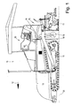
- the Fig. 1 shows schematically a paver 10, which is inventively designed so that it not only serves to produce an asphalt road surface, but is also suitable for the production of a concrete pavement. Above all, the paver 10 is also suitable for applying a concrete topcoat to an existing asphalt pavement whose worn overlay is removed by, for example, milling.
- the paver 10 has a chassis 11, which is formed in the embodiment shown as a crawler chassis.
- the chassis of the paver 10 can also be a wheel drive.
- a trough-like or trough-shaped reservoir 13 is arranged at the front of the paver 10.
- the reservoir 13 serves to receive a supply of serving for the production of the pavement material, namely an asphalt mixture, when the paver 10, an asphalt pavement is made.
- a conveying member in particular a scraper conveyor 14 (FIG. Fig. 5 )
- the asphalt mixture is transported from the reservoir 13 against the production direction 12 to a rear end 14 of the paver 10.
- the paver 10 has at the rear end 14, behind the chassis 11, via a distributor screw 15 which extends transversely to the production direction 12 and serves to distribute the material for the production of the road surface over the entire working width of the paver 10 evenly.
- a smoothing device in which the road paver 10 shown here is a screed 17.
- the screed 17 and the auger 16 are suspended from two support arms 18.
- the support arms 18 are pivotally mounted by the hydraulic cylinder 19 on the chassis 11 for moving up and down the screed 17 and the auger 16.
- the screed 17 can be both operatorunver selectedlich and be variable in width. Such a modification of the working width of the road paver 10 permitting screed 17 is shown in the figures.
- This screed 17 has a central main beam 20 and two on opposite sides of the same transversely movable to the production direction 12 movable mats 21st
- the paver 10 shown here has for processing concrete 33 to a concrete pavement or a concrete cover layer 32 via a plurality of compression means, which are inventively designed as Rüttel Sciences 23.
- the vibrating bodies 23 are preferably equally designed vibrating bottles.
- the vibrating body 23 are arranged between the chassis 11 and the screed 17. This arrangement is such that all vibrating bodies 23 are arranged hanging on a support 24 connected to the support arms 18.
- two extending over the respective working width of the paver 10 parallel rows, each with a plurality of vibrating bodies 23 attached to the support arms 18 movable up and down carrier 24.
- the road paver 10 has only one row of a plurality of vibrating bodies 23, which may be arranged both in front of and behind the auger 16.
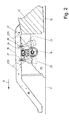
- the carrier 24 has a transversely to the production direction 12 extending rod 25, which may optionally be formed like a tube. Opposite ends of the rod 25 are telescopic, whereby the rod 25 to the variable working width of the paver 10, namely the respective width of the screed 17, is adjustable. The movable ends of the rod 25 are moved together or apart by suitable drives, in particular by hydraulic cylinders or racks, to adapt to the working width of the paver 10.
- Each vibrator body 23 is associated with a displaceable on the rod 25 sleeve 26.
- On the sleeve 26 of the respective Ganttel Sciences 23 is connected to a handle-like upper support rod 27 or a holding tube.
- In the support rod 27 of each Ganttel Sciencess 23 is a vertical slot 28.
- the distance of the Garttel Sciences 23 to each other is variable by a displacement of the respective connected to the support rod 27 sleeve 26 on the rod 25.
- the distance adjustment of the vibrating body 23 transversely to the production direction 12 takes place in the embodiment of Fig.
- the vibrating bodies 23 which are suspended on one or, if appropriate, also a plurality of rods 25, can be folded up into the in the case of non-use, for example if the road paver 10 is to be used for the production of asphalt road surfaces Fig. 2 dashed shown non-use position. This can be done manually, but also by appropriate part-turn actuators.
- the cylindrical vibrating bodies 23, which are preferably designed as vibrating bottles, are provided internally with a vibration exciter which is formed for example by an imbalance drive.
- the imbalance drive or any other vibration generator are electrically operated with an electric motor arranged in the vibrating body 23 or hydraulically or pneumatically. The energy required for this is supplied by the drive of the paver 10.
- the shaking movements of the vibrating bodies 23 are preferably directed radially to the longitudinal central axis 30 of the vibrating body 23, in any direction or circumferentially. However, it is also conceivable, alternatively or additionally, to move the vibrating bodies 23 shaking or vibrating in the direction of the longitudinal central axis 30.
- the concrete 33 is as shown in the Fig. 5
- a concrete mixer on opposite longitudinal sides of the paver 10 on the base 31 unloaded, as a concrete pile 34 on opposite sides of the paver 10.
- the paver 10 in the production direction 12 reach the concrete piles 34 in the sphere of influence of opposite outer ends of the auger 16th whereby the concrete 33 of the concrete piles 34 is distributed substantially evenly over the entire working width of the road paver 10 in front of the screed 17.
- the pre-screed 17 accumulating stock of concrete 33 (FIG. Fig. 2 ) is compressed by the Rüttel Sciencesn 23.
- the vibrating body 23 are guided hanging under the carriers 24, in such a way that they are held laterally by the support rods 27, so in the production direction 12 and in the direction transversely thereto - apart from the Haittelioloen - can not move significantly.
- the vibrating bodies 23 dip at least partially into the concrete 33.
- the shaking or oscillating movements of the vibrating body 23 of the concrete 33 is excited before the screed 17 to be shaken or pulsating movements and so compacted.
- the degree of compaction can be adapted to the type and mixing ratio, in particular the consistency, of the concrete 23.
- the corresponding settings and adjustments are preferably carried out by controls and adjusting drives, which can be influenced by the operator from the control station 35 of the road paver 10.
- the screed 17 When manufacturing the cover layer 32 formed from the concrete 33, the screed 17 is not operated floating as usual in the production of asphalt pavements, but fixed in height.
- the screed 17 is preferably rigidly suspended from the support arms 18, as well as the auger 16 and the carrier 24 for the Rüttel stresses 23. Also, the support arms 18 are not moved. As a result, the height of the screed 17 relative to the chassis 11 remains unchanged during the production of the cover layer 32 formed from the concrete 33. In this way, the screed 17 pushes not only with its own weight, but also with the weight of the paver 10 on the concrete 33 to form the cover layer 32.
- the screed 17 is raised or lowered by pivoting the actuatable by the hydraulic cylinders 19 support arms 18.
- the fixed in height or rigidly guided screed 17 can by the controller, which is preferably a leveling automatic, if necessary, the height and bank of the screed 17 change.
- the road paver 10 a pavement made of asphalt, it is easily convertible by only the vibrating body 23 are pivoted about the rod 25 by turning the sleeves 26 in the in the Fig. 2 Dashed position shown. As a result, the vibrating bodies 23 are brought into a rest position for installing asphalt, for which they are not needed. In addition, the screed 17 is then operated floating. Conversely, the paver 10 can be easily retrofitted for the installation of concrete 33.
- a further alternative embodiment of the road paver for carrying out the method described above is characterized in that the screed 17 is replaced by a smoothing device having a rail extending transversely to the production direction 12.
- the rail of the smoothing device is essentially fashioned rigidly behind the chassis 11 of the paver 10 during the production of the cover layer 33, and preferably on the support arms 18th
Landscapes
- Engineering & Computer Science (AREA)
- Architecture (AREA)
- Civil Engineering (AREA)
- Structural Engineering (AREA)
- Road Paving Machines (AREA)
Applications Claiming Priority (1)
| Application Number | Priority Date | Filing Date | Title |
|---|---|---|---|
| DE102009038007A DE102009038007A1 (de) | 2009-08-20 | 2009-08-20 | Verfahren zur Herstellung eines Straßenbelags, vorzugsweise eines Beton-Straßenbelags, und Straßenfertiger |
Publications (1)
| Publication Number | Publication Date |
|---|---|
| EP2287403A2 true EP2287403A2 (fr) | 2011-02-23 |
Family
ID=42596570
Family Applications (1)
| Application Number | Title | Priority Date | Filing Date |
|---|---|---|---|
| EP10007646A Withdrawn EP2287403A2 (fr) | 2009-08-20 | 2010-07-23 | Procédé de fabrication d'un revêtement routier, de préférence d'un revêtement routier en béton, et finisseuse de route |
Country Status (3)
| Country | Link |
|---|---|
| US (1) | US20110044758A1 (fr) |
| EP (1) | EP2287403A2 (fr) |
| DE (1) | DE102009038007A1 (fr) |
Cited By (4)
| Publication number | Priority date | Publication date | Assignee | Title |
|---|---|---|---|---|
| CN102168398A (zh) * | 2011-03-15 | 2011-08-31 | 河北路桥集团有限公司 | 一种大跨度道路混凝土路面摊铺机 |
| CN112942031A (zh) * | 2021-04-16 | 2021-06-11 | 武汉安盛居装饰工程有限公司 | 一种用于道路硬化施工装置的摊铺机 |
| CN114108413A (zh) * | 2021-12-04 | 2022-03-01 | 广东盈辉建设工程有限公司 | 一种提高路面施工平整度的方法 |
| CN114934422A (zh) * | 2022-05-27 | 2022-08-23 | 江苏金堰交通工程有限公司 | 一种沥青路面平整装置 |
Families Citing this family (8)
| Publication number | Priority date | Publication date | Assignee | Title |
|---|---|---|---|---|
| CN102411591A (zh) * | 2010-09-21 | 2012-04-11 | 阿里巴巴集团控股有限公司 | 一种信息处理的方法及设备 |
| JP2018188890A (ja) * | 2017-05-09 | 2018-11-29 | 鹿島道路株式会社 | 舗装機械 |
| ES1195909Y (es) * | 2017-10-16 | 2018-01-19 | Agusti Y Masoliver S A | Extendedora de aglomerado de asfalto para asfaltar una superficie que debe ser asfaltada |
| CN113186784B (zh) * | 2021-04-26 | 2022-06-14 | 徐州工业职业技术学院 | 一种用于监控摊铺机熨平板仰角变化的装置 |
| CN113215931B (zh) * | 2021-04-26 | 2022-06-14 | 徐州工业职业技术学院 | 一种具有摊铺机熨平板仰角变化监控功能的装置 |
| CN116219835A (zh) * | 2023-04-10 | 2023-06-06 | 孙子坤 | 一种沥青混凝土道路施工压实机 |
| CN116949896B (zh) * | 2023-08-31 | 2026-02-10 | 中冶南方城市建设工程技术有限公司 | 连续配筋混凝土底部振捣装置及其施工方法 |
| CN117344602A (zh) * | 2023-09-08 | 2024-01-05 | 中建海峡建设发展有限公司 | 一种地基浇筑混凝土摊铺装置 |
Family Cites Families (13)
| Publication number | Priority date | Publication date | Assignee | Title |
|---|---|---|---|---|
| US2138103A (en) * | 1937-08-09 | 1938-11-29 | Viber Company | Road paving machine |
| US2248103A (en) * | 1938-04-06 | 1941-07-08 | Mall Arthur William | Road vibrator |
| US2382096A (en) * | 1944-02-14 | 1945-08-14 | Viber Company | Paving machine |
| US3362308A (en) * | 1965-10-23 | 1968-01-09 | William H Ross | Concrete gutter and curb forming machine |
| US3555983A (en) * | 1968-08-02 | 1971-01-19 | Cmi Corp | Paving grout control device |
| US3753621A (en) * | 1971-04-16 | 1973-08-21 | East Moline Metal Prod Co | Concrete-working machine with walking vibrators |
| US4128359A (en) * | 1977-11-14 | 1978-12-05 | Cooper Jr Charles R | Self-propelled concrete vibrator apparatus |
| CH655966A5 (de) * | 1981-04-07 | 1986-05-30 | Joseph Voegele Ag | Fahrbarer fertiger. |
| US5983165A (en) * | 1997-06-04 | 1999-11-09 | Minnich/ Maginnis Mfg. Co., Inc. | Accelerometer-based monitoring of concrete consolidation |
| US5988939A (en) * | 1997-06-27 | 1999-11-23 | Allen Engineering Corp. | Universal bridge deck vibrating system |
| US6551018B2 (en) * | 2001-03-29 | 2003-04-22 | Blaw-Knox Construction Equipment Corporation | Apparatus for tamping paving material |
| US6857815B2 (en) * | 2002-06-14 | 2005-02-22 | Allen Engineering Corporation | Acoustic impedance matched concrete finishing |
| DE102008007308B3 (de) * | 2008-02-02 | 2009-08-13 | Abg Allgemeine Baumaschinen-Gesellschaft Mbh | Vorrichtung zum Verdichten von Straßenbaustoffen |
-
2009
- 2009-08-20 DE DE102009038007A patent/DE102009038007A1/de not_active Withdrawn
-
2010
- 2010-07-23 EP EP10007646A patent/EP2287403A2/fr not_active Withdrawn
- 2010-08-09 US US12/852,764 patent/US20110044758A1/en not_active Abandoned
Non-Patent Citations (1)
| Title |
|---|
| None |
Cited By (7)
| Publication number | Priority date | Publication date | Assignee | Title |
|---|---|---|---|---|
| CN102168398A (zh) * | 2011-03-15 | 2011-08-31 | 河北路桥集团有限公司 | 一种大跨度道路混凝土路面摊铺机 |
| CN102168398B (zh) * | 2011-03-15 | 2013-07-03 | 河北广通路桥工程有限公司 | 一种大跨度道路混凝土路面摊铺机 |
| CN112942031A (zh) * | 2021-04-16 | 2021-06-11 | 武汉安盛居装饰工程有限公司 | 一种用于道路硬化施工装置的摊铺机 |
| CN112942031B (zh) * | 2021-04-16 | 2023-12-08 | 武汉安盛居装饰工程有限公司 | 一种用于道路硬化施工装置的摊铺机 |
| CN114108413A (zh) * | 2021-12-04 | 2022-03-01 | 广东盈辉建设工程有限公司 | 一种提高路面施工平整度的方法 |
| CN114934422A (zh) * | 2022-05-27 | 2022-08-23 | 江苏金堰交通工程有限公司 | 一种沥青路面平整装置 |
| CN114934422B (zh) * | 2022-05-27 | 2023-09-29 | 江苏金堰交通工程有限公司 | 一种沥青路面平整装置 |
Also Published As
| Publication number | Publication date |
|---|---|
| US20110044758A1 (en) | 2011-02-24 |
| DE102009038007A1 (de) | 2011-03-03 |
Similar Documents
| Publication | Publication Date | Title |
|---|---|---|
| EP2287403A2 (fr) | Procédé de fabrication d'un revêtement routier, de préférence d'un revêtement routier en béton, et finisseuse de route | |
| DE2624212C2 (de) | Fahrbare Maschine zum kontinuierlichen Nivellieren und Verdichten der Schotterbettung eines Gleises | |
| DE2713460A1 (de) | Verfahren und vorrichtung zur abtragen einer strassendecke in einer vorgegebenen ebene | |
| EP0560021B1 (fr) | Véhicule pour la réparation de revêtements routiers | |
| DE1784696A1 (de) | Maschine zum Auftragen von verformbarem Strassendeckenmaterial auf eine Stra?tung | |
| DE3709974A1 (de) | Vorrichtung zum einbringen von bewehrungsstaeben in eine fahrbahndecke aus beton | |
| EP2412872A1 (fr) | Poutre lisseuse et finisseuse de route avec poutre lisseuse | |
| DE2147691A1 (de) | Vorrichtung zum verdichten bei der endbehandlung von strassendecken aus heissem mischmaterial | |
| CH488863A (de) | Vorrichtung zur stufenlosen Verstellung der Arbeitsbreite von Strassenfertigern für den Bau von Schwarzdecken und Betonbelägen | |
| DE10038943A1 (de) | Strassenfertiger und Einbauverfahren | |
| WO2023209200A1 (fr) | Finisseuse d'asphalte coulé | |
| EP1582629A1 (fr) | Finisseuse et procédé pour la pose simultanée de plusieurs couches de matériaux | |
| WO2011042130A1 (fr) | Procédé et dispositif permettant d'armer une superstructure de voie de circulation | |
| DD253267A5 (de) | Fahrbare anlage zur kontinuierlichen erneuerung der schienen und schwellen eines gleises | |
| DE19652396C1 (de) | Deckenfertiger | |
| DE2833311A1 (de) | Maschine zur herstellung eines strassenbelags | |
| DE2554710C3 (de) | Verfahren zum Instandsetzen einer bituminösen Fahrbahndeckschicht und Bauzug zur Durchführung des Verfahrens | |
| DE1759744A1 (de) | Auf Raupen oder Raedern fahrender Strassendeckenfertiger | |
| DE939158C (de) | Fertiger, insbesondere fuer bituminoese Strassendecken, mit einem Raupenfahrgestell | |
| EP1897999A2 (fr) | Procédé pour obtenir une finisseuse pour routes à plusieurs couches destiné à l'installation de revêtements de routes à plusieurs couches et finisseuse pour routes à plusieurs couches | |
| DE3117544A1 (de) | Duebelsetzen im betonstrassenbau | |
| EP2166152A1 (fr) | Procédé et dispositif d'amélioration ou de réparation d'installations de voies ferrées | |
| DE102022124731A1 (de) | Automatisches mechanisches system zum positionieren der abziehbohle in der anfangspflastertiefe | |
| DE102005019139B4 (de) | Einbaubohle mit vorgelagerter Verdichtungseinheit | |
| WO2005038140A1 (fr) | Finisseur a coffrage glissant pour realiser des revetements de surface |
Legal Events
| Date | Code | Title | Description |
|---|---|---|---|
| PUAI | Public reference made under article 153(3) epc to a published international application that has entered the european phase |
Free format text: ORIGINAL CODE: 0009012 |
|
| AK | Designated contracting states |
Kind code of ref document: A2 Designated state(s): AL AT BE BG CH CY CZ DE DK EE ES FI FR GB GR HR HU IE IS IT LI LT LU LV MC MK MT NL NO PL PT RO SE SI SK SM TR |
|
| AX | Request for extension of the european patent |
Extension state: BA ME RS |
|
| STAA | Information on the status of an ep patent application or granted ep patent |
Free format text: STATUS: THE APPLICATION IS DEEMED TO BE WITHDRAWN |
|
| 18D | Application deemed to be withdrawn |
Effective date: 20140201 |