EP2287433A2 - Système de vitrage résistant contre des explosions - Google Patents
Système de vitrage résistant contre des explosions Download PDFInfo
- Publication number
- EP2287433A2 EP2287433A2 EP10171880A EP10171880A EP2287433A2 EP 2287433 A2 EP2287433 A2 EP 2287433A2 EP 10171880 A EP10171880 A EP 10171880A EP 10171880 A EP10171880 A EP 10171880A EP 2287433 A2 EP2287433 A2 EP 2287433A2
- Authority
- EP
- European Patent Office
- Prior art keywords
- sheet
- retaining member
- edge region
- projection
- portions
- Prior art date
- Legal status (The legal status is an assumption and is not a legal conclusion. Google has not performed a legal analysis and makes no representation as to the accuracy of the status listed.)
- Withdrawn
Links
- 239000000463 material Substances 0.000 claims abstract description 13
- 239000005340 laminated glass Substances 0.000 claims abstract description 12
- 229920001296 polysiloxane Polymers 0.000 claims description 28
- 230000015572 biosynthetic process Effects 0.000 claims description 19
- 238000005755 formation reaction Methods 0.000 claims description 19
- 239000004411 aluminium Substances 0.000 claims description 15
- 229910052782 aluminium Inorganic materials 0.000 claims description 15
- XAGFODPZIPBFFR-UHFFFAOYSA-N aluminium Chemical compound [Al] XAGFODPZIPBFFR-UHFFFAOYSA-N 0.000 claims description 14
- 239000012790 adhesive layer Substances 0.000 claims description 10
- 239000010410 layer Substances 0.000 claims description 4
- NIXOWILDQLNWCW-UHFFFAOYSA-N acrylic acid group Chemical group C(C=C)(=O)O NIXOWILDQLNWCW-UHFFFAOYSA-N 0.000 claims description 2
- 239000000853 adhesive Substances 0.000 claims 1
- 230000001070 adhesive effect Effects 0.000 claims 1
- 229910052751 metal Inorganic materials 0.000 claims 1
- 239000002184 metal Substances 0.000 claims 1
- 239000011521 glass Substances 0.000 description 62
- 125000006850 spacer group Chemical group 0.000 description 5
- 230000008901 benefit Effects 0.000 description 4
- 238000005192 partition Methods 0.000 description 3
- 238000004140 cleaning Methods 0.000 description 2
- 238000000034 method Methods 0.000 description 2
- 230000004048 modification Effects 0.000 description 2
- 238000012986 modification Methods 0.000 description 2
- 230000037452 priming Effects 0.000 description 2
- 230000008569 process Effects 0.000 description 2
- 150000001398 aluminium Chemical class 0.000 description 1
- 230000001668 ameliorated effect Effects 0.000 description 1
- 230000001419 dependent effect Effects 0.000 description 1
- 239000002360 explosive Substances 0.000 description 1
- 230000006872 improvement Effects 0.000 description 1
- 238000010297 mechanical methods and process Methods 0.000 description 1
- 230000005226 mechanical processes and functions Effects 0.000 description 1
- 230000007246 mechanism Effects 0.000 description 1
- 229920000515 polycarbonate Polymers 0.000 description 1
- 239000004417 polycarbonate Substances 0.000 description 1
- 230000000717 retained effect Effects 0.000 description 1
- 230000003313 weakening effect Effects 0.000 description 1
Images

Classifications
-
- E—FIXED CONSTRUCTIONS
- E06—DOORS, WINDOWS, SHUTTERS, OR ROLLER BLINDS IN GENERAL; LADDERS
- E06B—FIXED OR MOVABLE CLOSURES FOR OPENINGS IN BUILDINGS, VEHICLES, FENCES OR LIKE ENCLOSURES IN GENERAL, e.g. DOORS, WINDOWS, BLINDS, GATES
- E06B3/00—Window sashes, door leaves, or like elements for closing wall or like openings; Layout of fixed or moving closures, e.g. windows in wall or like openings; Features of rigidly-mounted outer frames relating to the mounting of wing frames
- E06B3/54—Fixing of glass panes or like plates
- E06B3/549—Fixing of glass panes or like plates by clamping the pane between two subframes
-
- E—FIXED CONSTRUCTIONS
- E06—DOORS, WINDOWS, SHUTTERS, OR ROLLER BLINDS IN GENERAL; LADDERS
- E06B—FIXED OR MOVABLE CLOSURES FOR OPENINGS IN BUILDINGS, VEHICLES, FENCES OR LIKE ENCLOSURES IN GENERAL, e.g. DOORS, WINDOWS, BLINDS, GATES
- E06B3/00—Window sashes, door leaves, or like elements for closing wall or like openings; Layout of fixed or moving closures, e.g. windows in wall or like openings; Features of rigidly-mounted outer frames relating to the mounting of wing frames
- E06B3/54—Fixing of glass panes or like plates
- E06B3/5454—Fixing of glass panes or like plates inside U-shaped section members
-
- E—FIXED CONSTRUCTIONS
- E06—DOORS, WINDOWS, SHUTTERS, OR ROLLER BLINDS IN GENERAL; LADDERS
- E06B—FIXED OR MOVABLE CLOSURES FOR OPENINGS IN BUILDINGS, VEHICLES, FENCES OR LIKE ENCLOSURES IN GENERAL, e.g. DOORS, WINDOWS, BLINDS, GATES
- E06B5/00—Doors, windows, or like closures for special purposes; Border constructions therefor
- E06B5/10—Doors, windows, or like closures for special purposes; Border constructions therefor for protection against air-raid or other war-like action; for other protective purposes
- E06B5/12—Doors, windows, or like closures for special purposes; Border constructions therefor for protection against air-raid or other war-like action; for other protective purposes against air pressure, explosion, or gas
Definitions
- the invention relates to a blast-resistant glazing system, comprising a sheet of blast resistant glazing material and a retaining member.
- Sheets of glazing material that are highly resistant to bomb blasts are known.
- One such material is certain types of specialist laminated glass.
- Each retaining member is secured to the building, structure, vehicle etc by suitable fastening means and the sheet of glazing material is mounted in the retaining member or members.
- each of two opposed edge regions of the sheet may be mounted in a respective retaining member.
- a known blast-resistant glazing system comprises a sheet of blast-resistant laminated glass and a retaining member in the form of an aluminium bar having a rebate (i.e. a U-sectioned slot) extending therealong.
- a rebate i.e. a U-sectioned slot
- an edge region of the glass sheet is inserted into the rebate and then silicone is injected into the gaps between the glass sheet and the surfaces of the rebate. Once the silicone has cured it forms a strong bond between the glass sheet and the retaining member.
- this known glazing system suffers from a number of problems.
- the surfaces of the edge region of the glass sheet and the surfaces of the rebate need to be carefully cleaned and primed to ensure satisfactory adhesion by the silicone, and it may be difficult to achieve this if the mounting is performed "on site”. It is also difficult, if not impossible, to ensure that the silicone has filled all the gaps between the edge region of the glass and the surfaces of the rebate. Insufficient filling can lead to insufficient adhesion.
- the silicone takes a long time (days or weeks) to cure fully and the adhesion between the retaining member and the glass sheet is weaker during this curing period.
- the final strength of the adhesion may be reduced if the glass sheet is inadvertantly moved, for example by the wind or members of the public, during the curing process. If the glass sheet is damaged, replacement is onerous as the cured silicone needs to be removed completely from the rebate and the rebate surfaces cleaned thoroughly before a replacement glass sheet can be fitted.
- the current invention provides an alternative blast-resistant glazing system.
- at least some of the problems mentioned above may be ameliorated or overcome.
- a blast-resistant glazing system comprising: a sheet of blast-resistant glazing material and a retaining member, the retaining member having two spaced opposed portions for receiving an edge region of the sheet therebetween with each one of the portions lying adjacent a respective major surface of the sheet, the sheet and the retaining member being provided with respective formations extending at respective angles relative to the major surfaces of the sheet so that withdrawal of the edge region of the sheet from between the portions is resisted by engagement between the formations.
- a blast-resistant glazing system comprising: a sheet of blast-resistant glazing material and a retaining member, the retaining member having two spaced opposed portions for receiving an edge region of the sheet therebetween so that each portion lies adjacent a respective major surface of the sheet, the sheet being provided with a projection extending outwardly from one of the major surfaces, the projection interlocking with one of the portions so that withdrawal of the edge region of the sheet from between the portions is resisted by engagement between the projection and said one of the portions.
- the glazing system comprises a sheet 10 of blast-resistant laminated glass and an elongate retaining member 11.
- the retaining member 11 has a first elongate part 12 and a second elongate part 13 held together parallel to one another by a plurality of bolts 14 which are spaced along the length of the retaining member 11.
- the first part 12 is generally L-shaped in section with a base 15 and an arm 16 meeting each other at 90°.
- the base 15 is provided with a plurality of threaded blind holes 17, which are spaced from each other along the base 15, and which extend into the base 15 from the free end of the base 15.
- the free end of the arm 16 is provided with a lip 18, which extends the full length of the arm 16, and which extends from the arm 16 parallel to and in the same direction as the base 15.
- the second part 13 is generally planar and has a thickened base edge 19 which is provided with a plurality of through holes 20 spaced along the length of the second part 13. Opposite to the base edge 19, the second part 13 is provided with a lip 21 which extends the full length of the second part 13 and which extends at 90° to the plane of the second part 13.
- first and second parts 12, 13 are assembled together with the thickened base edge 19 of the second part abutting the free end of the base 15 of the first part 12.
- Each through hole 20 is aligned with a respective one of the threaded blind holes 17 and a respective bolt 14 passes through the through hole 20 and is threadedly engaged with the threaded blind hole 17.
- the arm 16 of the first part 12 lies parallel to and opposite the second part 13 so that a generally U-sectioned channel or rebate 22 is formed between the first and second parts 12, 13.
- the lip 18 on the first part 12 and the lip 21 on the second part 13 extend towards one another to form a slot therebetween, located at the mouth of the U-sectioned rebate 22.
- a first recess 23 is provided in the U-sectioned rebate 22, on the first part 12, between the lip 18 and the base 15, and a second recess 24 is provided in the U-sectioned rebate 22, on the second part 13, between the lip 21 and the thickened base edge 19.
- a rubber spacer 40 lies at the base of the rebate 22 adjacent the base 15 of the first part 12.
- the laminated glass sheet 10 is rectangular with one edge 25 shown in Figure 1 .
- a respective projection 26, 27 is provided on each one of the two opposed major surfaces 28, 29 of the glass sheet 10 adjacent the edge 25 of the sheet 10.
- the two projections 26, 27 are identical and only one will be described in detail.
- the projection 26 extends the full length of and parallel to the edge 25 of the glass sheet 10.
- the projection 26 has a first layer consisting of a strip of very high bond (VHB) tape 30.
- VHB very high bond
- a preferred tape is 25mm wide 4918F VHB acrylic foamed tape supplied by 3M Ltd.
- One side of the VHB tape is adhered to the major surface 28 of the glass sheet 10 at the edge region.
- the other side of the VHB tape 30 is adhered to a strip of aluminium 31, which forms a second outer layer of the projection 26.
- the VHB tape 30 is about 2 mm thick and the aluminium strip 31 is about 3 mm thick.
- the other projection 27 is shown with a strip of VHB tape 32 and a strip of aluminium 33.
- the retaining member 11 may be used to mount the sheet of laminated glass 10 to a building, or to a structure such as a glass wall, a partition or a shelter (eg a bus shelter). Part of the building or structure is shown at 41.
- a structure such as a glass wall, a partition or a shelter (eg a bus shelter).
- Part of the building or structure is shown at 41.
- two or four retaining members 11 will be used. When two retaining members 11 are used, they are used, respectively, to mount opposed edge regions of the sheet 10. When four retaining members 11 are used, each retaining member 11 is used to mount a respective edge of the sheet 10.
- Each retaining member 11 is secured to the building, structure 41 etc using suitable retaining means such as bolts (not shown).
- the bolts 14 are loosened and the second part 13 is pulled away from the first part 12 so as to increase the width of the slot between the first part lip 18 and the second part lip 21.
- the edge region of the sheet 10 is then inserted between the first and second parts 12, 13 until the projections 26, 27 have passed beyond the lips 18, 21 and until the edge 25 of the glass sheet 10 lies against the rubber spacer 40.
- the bolts 14 are then tightened so that the thickened base edge 19 of the second part 13 abuts the base 15 of the first part 12.
- the projection 26 lies in the recess 23 in the first part 12 and the projection 27, on the other major surface of the sheet 10, lies in the recess 24 in the second part 13. Hence, the projection 26 is interlocked with the lip 18 on the first part 12 and the projection 27 is interlocked with the lip 21 on the second part 13.
- the dimensions of the first and second parts 12,13, the thickness of the glass sheet 10 and the thicknesses of the two layers of very high bond tape 30, 32 and the two strips of aluminium 31, 33 are such that the edge region of the glass sheet 10 with the two projections 26, 27 is clamped between the two parts 12, 13.
- the strips of VHB tape 30, 32 are compressed by about 10%.
- the force of the blast will generally act on one or the other of the major surfaces 28, 29 of the glass sheet 10.
- the glass sheet 10 tends to bend between the two retaining members 11 and this, in turn, tends to withdraw the edge regions of the glass sheet 10 from the retaining members 11.
- This withdrawal is resisted by two mechanisms. Firstly, as the edge region of the glass sheet 10 is clamped between the first and second parts 12, 13, withdrawal of the edge region is resisted by friction between the aluminium strips 31, 33 and the first and second parts 12, 13 - as the projections 26, 27 move towards the lips 18, 21.
- the aluminium strip 31 of the projection 26 engages the lip 18 and the aluminium strip 33 of the projection 27 engages the lip 21.
- the engagement between the projections 26, 27 and the lips 18, 21 prevents further withdrawal of the edge region of the glass sheet 10 from the retaining member 11.
- the adhesion of the VHB tape 30, 32 to the glass sheet 10 and also to the aluminium strips 31, 33 can be readily carried out under factory conditions - where the surfaces can be carefully cleaned and curing of the VHB tape 30, 32 can be carried out under controlled conditions (eg of temperature and humidity). Adhesion is preferably carried out in accordance with the instructions of the manufacturer of the VHB tape. In this way, optimum bonding can be achieved.
- the glass sheet 10, with all the necessary projections 26, 27 already formed thereon can then be taken to the building or structure where is is to be used and mounted within the retaining members 11 as described above.
- the process of mounting the glass sheet 10 (with pre-formed projections 26, 27) into the retaining members 11 is a simple mechanical process and does not require adhesion between the glass sheet 10 and the retaining members 11. It can be carried out readily on site by personnel with no experience of silicone bonding. Unlike the conventional blast-resistant glazing system described above, which requires formation of a silicone bond between the glass and the retaining members, there is no risk of insufficient bonding due to incomplete filling of the gaps between the glass and the rebate with silicone, no risk of inadequate bonding caused by dirty surfaces and no risk of weakening of the bond by movement of the glass sheet during curing.
- the Figure 1 embodiment of the current invention has another advantage in that, if the bonding of the VHB tape 30, 32 is performed in the factory, before the glass 10 is mounted to the building or structure, the glazing system provides full blast protection as soon as the glass 10 is mounted in the retaining members 11. This is a significant improvement over the conventional silicone bonding system in which full protection is not achieved for days or weeks until the curing of the silicone is completed.
- Another advantage of the embodiment described above with reference to Figure 1 is that replacement of glass sheets 10 is rapid and easy. As there is no bonding between the retaining members 11 and the glass sheet 10 there is no need to remove previous bonding material (such as silicone in the conventional system) and no need to clean the surfaces of the retaining member. In order to replace a glass sheet 10, the bolts 14 are loosened, the second part 13 is separated from the first part 12 and the old glass sheet 10 is removed. A new glass sheet 10 is then mounted in the retaining members 11 as described above.
- previous bonding material such as silicone in the conventional system
- a further advantage of the embodiment described above with reference to Figure 1 is that the glazing system can accommodate different thicknesses of blast resistant glass sheet with minimal modification.
- the thickness of the aluminium strips 31, 33 can be increased so that the glass sheet 10 with the projections 26, 27 is still clamped between the first and second parts 12, 13.
- the aluminium strips 31, 33 can be made thinner.
- the gap between the arm 16 of the first part 12 and the second part 13 can be increased by inserting a spacer or spacers (not shown in Figure 1 ) between the thickened base edge 19 of the second part 13 and the base 15 of the first part 12.
- the formations it is prefered for the formations to be interlocked but not actually in engagement with one another, in the normal position of the glass sheet. This allows for some blast energy to be absorbed by friction as the glass sheet moves relative to the retaining member and before the formations come into engagement. However, this is not essential and the formations may be in engagement in the normal position of the glass sheet. Although clamping of the glass sheet by the retaining member is useful as it generates friction as the formations move into engagement, clamping is also not essential and the glass sheet may be loosely received in the retaining member - as long as the formations are held in interlocking relationship so that they are either engaged or come into engagement to resist withdrawal of the glass sheet.
- laminated glass sheet and other blast-resistant glazing materials such as polycarbonate sheet may be used.
- the VHB tape 30, 32 serves as an adhesive layer between the glass sheet 10 and the aluminium strips 31, 33.
- Other types of adhesive layer may be used.
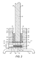
- FIG. 2 A second embodiment is shown in Figure 2 . Parts of this embodiment that are identical or similar to coresponding parts of the Figure 1 embodiment will be given the same reference numerals and will not be described in detail.
- each strip of VHB tape 30, 32 used in the first embodiment is replaced by a strip of structural silicone 34, 35.
- a suitable type of structural silicone is available from Dow Coming as 995 silicone.
- Each strip 34, 35 of structural silicone has a thickness of about 6mm (before clamping between the first and second parts 12, 13). As the structural silicone 34, 35 is thicker than the VHB tape 30, 32 a spacer 36 is placed between the first and second parts 12, 13.
- a structural silicone strip 34, 35 the silicone is applied to the glass sheet 10, after cleaning and priming of the glass sheet, in a clean environment maintained at a suitable temperature and humidity.
- the aluminium strip 31, 33 again cleaned and primed, is then applied to the outside of the silicone.
- the silicone is then left to cure completely in the clean environment. Cleaning, priming and curing are preferably carried out in accordance with the instructions of the manufacturer of the silicone.
- each silicone strip 34, 35 together with the associated aluminium strip 31, 33 makes up a projection that interlocks with one of the lips 18, 21, in the same way as described above in respect of the first embodiment.
- the blast-proof glazing system of the current invention is suitable for use, for example, in buildings; other structures such as bus shelters, partitions, walls etc; as well as in transport means such as ships and vehicles etc.
- Bus shelters using the current blast-proof glazing system were tested for resistance to bomb blasts according to the ISO/FDIS 16933 EXV 25 standard. This involves submitting the bus shelter to the equivalent of a 100kg TNT car bomb with a distance of 25m between the explosive and the bus shelter. Two bus shelters were tested.
- the first shelter used 13.5mm thick laminated glass sheets and also 17.5mm thick laminated glass sheets mounted to a strong bus shelter frame using the glazing system of the Figure 1 embodiment (using VHB tape 30, 32 as the adhesive layer).
- the second bus shelter also used 13.5mm laminated glass sheets and 17.5mm laminated glass sheets mounted to a strong bus shelter frame, this time using the glazing system of the Figure 2 embodiment (using the structural silicone strips 34, 35).
- Each glass sheet, in both bus shelters was mounted using two retaining members - one at the top and one at the bottom.
- the blast-resistant glazing system performed well and all of the glass sheets were retained by the bus shelter frames - ie none of the glass sheets broke free.
- the glazing system of the second bus shelter (using silicone strips 34, 35 as the adhesive layer) was considered to perform slightly better than the glazing system of the first bus shelter (using VHB tape strips 30, 32 as the adhesive layer). This is because whereas a degree of loosening of the glass 10 in the retaining members 11 was observed after the blast, when VHB tape 30, 32 was used, no such loosening was observed when silicone strips 34, 35 were used.
Landscapes
- Engineering & Computer Science (AREA)
- Civil Engineering (AREA)
- Structural Engineering (AREA)
- Securing Of Glass Panes Or The Like (AREA)
Applications Claiming Priority (1)
| Application Number | Priority Date | Filing Date | Title |
|---|---|---|---|
| GB0913933A GB2472459B (en) | 2009-08-07 | 2009-08-07 | Blast-resistant glazing system |
Publications (2)
| Publication Number | Publication Date |
|---|---|
| EP2287433A2 true EP2287433A2 (fr) | 2011-02-23 |
| EP2287433A3 EP2287433A3 (fr) | 2013-12-04 |
Family
ID=41129901
Family Applications (1)
| Application Number | Title | Priority Date | Filing Date |
|---|---|---|---|
| EP10171880.7A Withdrawn EP2287433A3 (fr) | 2009-08-07 | 2010-08-04 | Système de vitrage résistant contre des explosions |
Country Status (4)
| Country | Link |
|---|---|
| US (1) | US20110030295A1 (fr) |
| EP (1) | EP2287433A3 (fr) |
| CA (1) | CA2711832A1 (fr) |
| GB (1) | GB2472459B (fr) |
Cited By (2)
| Publication number | Priority date | Publication date | Assignee | Title |
|---|---|---|---|---|
| WO2012121589A1 (fr) * | 2011-03-07 | 2012-09-13 | Allure Bouw B.V. | Assemblage d'un châssis de fenêtre et d'un panneau de verre isolant |
| RU2683360C2 (ru) * | 2014-05-27 | 2019-03-28 | ГАРДИАН ГЛАСС ЭлЭлСи. | Оконная рамная система для стеклопакета с вакуумной изоляцией |
Families Citing this family (7)
| Publication number | Priority date | Publication date | Assignee | Title |
|---|---|---|---|---|
| US9417001B2 (en) * | 2012-05-18 | 2016-08-16 | Whirlpool Corporation | Top cooling module for a refrigerator |
| EP3092361A4 (fr) * | 2014-01-10 | 2017-10-25 | Insite Manufacturing Pty Ltd | Panneau et assemblage de panneau |
| ES2592809A1 (es) * | 2016-07-21 | 2016-12-01 | Oscar Torrabias Cantal | Elemento estructural para fijación de mamparas de cristal |
| GB2555473A (en) | 2016-10-31 | 2018-05-02 | Zucker John | Frame assembly for sheet material |
| WO2020147908A1 (fr) * | 2019-01-14 | 2020-07-23 | Vkr Holding A/S | Solution de cadre avec joint d'étanchéité venant en butée contre la surface d'une unité vig |
| US20210348437A1 (en) * | 2020-05-05 | 2021-11-11 | TEDnovo LLC | Frameless window installation assembly |
| CN112627693A (zh) * | 2020-12-21 | 2021-04-09 | 合肥博居门业有限公司 | 一种防爆窗及安装方法 |
Family Cites Families (20)
| Publication number | Priority date | Publication date | Assignee | Title |
|---|---|---|---|---|
| US2064530A (en) * | 1934-03-21 | 1936-12-15 | Pittsburgh Plate Glass Co | Double glazed window |
| US4115964A (en) * | 1975-08-08 | 1978-09-26 | Montrouil Enterprises, Inc. | Windows and method of making the same |
| DE2801555A1 (de) * | 1978-01-14 | 1979-07-19 | Roehm Gmbh | Einbruchhemmende schutzverglasung |
| BE902247A (nl) * | 1985-04-22 | 1985-08-16 | Glas Art P V B A | Bevestiging voor glas in metalen profielen. |
| DE3918158C1 (fr) * | 1989-06-03 | 1990-07-26 | Flachglas Ag, 8510 Fuerth, De | |
| US4947597A (en) * | 1989-11-13 | 1990-08-14 | Western Reserve Plastics | Window mounting assembly |
| DE9315811U1 (de) * | 1993-10-18 | 1995-02-16 | Fachverband Glasdach- und Metallbau e.V., 50670 Köln | Wand- oder Türelement mit Glasscheibe |
| US5444958A (en) * | 1993-11-02 | 1995-08-29 | Lu; Ching-Nan | Door frame |
| DE4433052A1 (de) * | 1994-09-16 | 1996-03-21 | Brose Fahrzeugteile | Vorrichtung zum Verbinden einer Fensterscheibe mit einem Fensterheber |
| NL1002128C2 (nl) * | 1996-01-19 | 1997-07-22 | Boomsma Prod Bv | Scheepsraam. |
| CA2205669C (fr) * | 1997-06-19 | 2000-05-16 | Paul W. Poirier | Methode et appareil utilises pour installer une pellicule de securite pour fenetre sur le pourtour d'un cadre de fenetre |
| US7082736B2 (en) * | 1998-11-04 | 2006-08-01 | Transit Care, Inc. | Process for retrofitting an existing bus window having rubber seals with metal members that define a retention space for a sacrificial member |
| IL127424A (en) * | 1998-12-07 | 2000-11-21 | M T D Ind Ltd | Blast protective window |
| DE19857982B4 (de) * | 1998-12-16 | 2006-06-14 | Haverkamp Gmbh | Fenster mit einer ein Sicherheitselement aufweisenden Fensterscheibe |
| US6434905B1 (en) * | 2000-08-02 | 2002-08-20 | C. R. Laurence Co., Inc. | Door rail system |
| US7104015B2 (en) * | 2002-02-22 | 2006-09-12 | Thoi Huu Huynh | Window assembly for buildings in seismic zones |
| US7827761B2 (en) * | 2003-06-23 | 2010-11-09 | Ppg Industries Ohio, Inc. | Plastic spacer stock, plastic spacer frame and multi-sheet unit, and method of making same |
| CN1918358A (zh) * | 2003-12-15 | 2007-02-21 | 纳幕尔杜邦公司 | 具有改进的抗猛烈撞击的结构完整性的防爆玻璃叠层片 |
| DE202006002480U1 (de) * | 2006-02-15 | 2007-06-28 | SWS Gesellschaft für Glasbaubeschläge mbH | Klemmvorrichtung zum Befestigen von Platten |
| GB0616582D0 (en) * | 2006-08-21 | 2006-09-27 | Honey Ian | Frame assembly for sheet material |
-
2009
- 2009-08-07 GB GB0913933A patent/GB2472459B/en not_active Expired - Fee Related
-
2010
- 2010-07-30 CA CA2711832A patent/CA2711832A1/fr not_active Abandoned
- 2010-08-04 EP EP10171880.7A patent/EP2287433A3/fr not_active Withdrawn
- 2010-08-05 US US12/851,067 patent/US20110030295A1/en not_active Abandoned
Non-Patent Citations (1)
| Title |
|---|
| None |
Cited By (2)
| Publication number | Priority date | Publication date | Assignee | Title |
|---|---|---|---|---|
| WO2012121589A1 (fr) * | 2011-03-07 | 2012-09-13 | Allure Bouw B.V. | Assemblage d'un châssis de fenêtre et d'un panneau de verre isolant |
| RU2683360C2 (ru) * | 2014-05-27 | 2019-03-28 | ГАРДИАН ГЛАСС ЭлЭлСи. | Оконная рамная система для стеклопакета с вакуумной изоляцией |
Also Published As
| Publication number | Publication date |
|---|---|
| US20110030295A1 (en) | 2011-02-10 |
| CA2711832A1 (fr) | 2011-02-07 |
| GB2472459A (en) | 2011-02-09 |
| GB2472459B (en) | 2011-10-19 |
| GB0913933D0 (en) | 2009-09-16 |
| EP2287433A3 (fr) | 2013-12-04 |
Similar Documents
| Publication | Publication Date | Title |
|---|---|---|
| EP2287433A2 (fr) | Système de vitrage résistant contre des explosions | |
| US6088979A (en) | Frame for supporting an auxiliary glazing and method for installing the improved frame | |
| AU2021200425B2 (en) | Frame Assembly for Retaining a Screen | |
| US10450743B2 (en) | Window and curtain wall mullions, transoms and systems | |
| CA2858724C (fr) | Isolant thermique pour paroi a rideau | |
| US11214961B2 (en) | Window and curtain wall mullions, transoms and systems | |
| US11982121B1 (en) | Retention clip assemblies, retention systems and methods | |
| DE102004062060B3 (de) | Fensterscheibe mit einem Sicherungselement | |
| US20130239501A1 (en) | Snap-in glass block system | |
| US8528281B2 (en) | Window and door assembly structures | |
| EP3610089B1 (fr) | Meneaux de fenêtre et mur-rideau, traverses et systèmes | |
| CN113167099A (zh) | 框架组件 | |
| US11053728B2 (en) | Frame assembly for sheet material | |
| CA2795650C (fr) | Systeme d'ancrage de vitrage | |
| DE202005012108U1 (de) | Verglasungssystem | |
| EP3314065B1 (fr) | Montants, traverses et systèmes de mur-rideau | |
| DE102006032364B4 (de) | Verglasungssystem | |
| WO2012153140A1 (fr) | Fenêtre résistant aux chocs améliorée et procédé d'installation | |
| KR102636624B1 (ko) | 방화문 하부씰 보양 커버 | |
| JP2010174584A (ja) | 耐震スリット材 | |
| AU2016203546B2 (en) | A frame to receive a mesh panel | |
| CN121897124A (zh) | 一种墙板安装结构及其安装方法 | |
| WO2008065105A1 (fr) | Structure de fenêtre ayant une plaque écran et un organe de fixation | |
| GB2434614A (en) | Fastener with detent formation |
Legal Events
| Date | Code | Title | Description |
|---|---|---|---|
| PUAI | Public reference made under article 153(3) epc to a published international application that has entered the european phase |
Free format text: ORIGINAL CODE: 0009012 |
|
| AK | Designated contracting states |
Kind code of ref document: A2 Designated state(s): AL AT BE BG CH CY CZ DE DK EE ES FI FR GB GR HR HU IE IS IT LI LT LU LV MC MK MT NL NO PL PT RO SE SI SK SM TR |
|
| AX | Request for extension of the european patent |
Extension state: BA ME RS |
|
| PUAL | Search report despatched |
Free format text: ORIGINAL CODE: 0009013 |
|
| AK | Designated contracting states |
Kind code of ref document: A3 Designated state(s): AL AT BE BG CH CY CZ DE DK EE ES FI FR GB GR HR HU IE IS IT LI LT LU LV MC MK MT NL NO PL PT RO SE SI SK SM TR |
|
| AX | Request for extension of the european patent |
Extension state: BA ME RS |
|
| RIC1 | Information provided on ipc code assigned before grant |
Ipc: E06B 5/12 20060101AFI20131029BHEP Ipc: E06B 3/54 20060101ALI20131029BHEP |
|
| 17P | Request for examination filed |
Effective date: 20140530 |
|
| RBV | Designated contracting states (corrected) |
Designated state(s): AL AT BE BG CH CY CZ DE DK EE ES FI FR GB GR HR HU IE IS IT LI LT LU LV MC MK MT NL NO PL PT RO SE SI SK SM TR |
|
| GRAP | Despatch of communication of intention to grant a patent |
Free format text: ORIGINAL CODE: EPIDOSNIGR1 |
|
| INTG | Intention to grant announced |
Effective date: 20141113 |
|
| STAA | Information on the status of an ep patent application or granted ep patent |
Free format text: STATUS: THE APPLICATION IS DEEMED TO BE WITHDRAWN |
|
| 18D | Application deemed to be withdrawn |
Effective date: 20150303 |