EP2287434A2 - Hermetische Verschlussvorrichtung für Schiebetüren und -fenster - Google Patents
Hermetische Verschlussvorrichtung für Schiebetüren und -fenster Download PDFInfo
- Publication number
- EP2287434A2 EP2287434A2 EP10382182A EP10382182A EP2287434A2 EP 2287434 A2 EP2287434 A2 EP 2287434A2 EP 10382182 A EP10382182 A EP 10382182A EP 10382182 A EP10382182 A EP 10382182A EP 2287434 A2 EP2287434 A2 EP 2287434A2
- Authority
- EP
- European Patent Office
- Prior art keywords
- hermeticity
- windows
- flat bar
- hermetic closure
- closure device
- Prior art date
- Legal status (The legal status is an assumption and is not a legal conclusion. Google has not performed a legal analysis and makes no representation as to the accuracy of the status listed.)
- Withdrawn
Links
- 238000006073 displacement reaction Methods 0.000 claims description 4
- 238000013459 approach Methods 0.000 description 6
- 229920001971 elastomer Polymers 0.000 description 4
- 239000004033 plastic Substances 0.000 description 4
- 239000005060 rubber Substances 0.000 description 4
- 238000005452 bending Methods 0.000 description 3
- 239000002245 particle Substances 0.000 description 2
- 230000003252 repetitive effect Effects 0.000 description 2
- 238000000926 separation method Methods 0.000 description 2
- 230000000694 effects Effects 0.000 description 1
- 230000000284 resting effect Effects 0.000 description 1
Images


Classifications
-
- E—FIXED CONSTRUCTIONS
- E06—DOORS, WINDOWS, SHUTTERS, OR ROLLER BLINDS IN GENERAL; LADDERS
- E06B—FIXED OR MOVABLE CLOSURES FOR OPENINGS IN BUILDINGS, VEHICLES, FENCES OR LIKE ENCLOSURES IN GENERAL, e.g. DOORS, WINDOWS, BLINDS, GATES
- E06B7/00—Special arrangements or measures in connection with doors or windows
- E06B7/16—Sealing arrangements on wings or parts co-operating with the wings
- E06B7/18—Sealing arrangements on wings or parts co-operating with the wings by means of movable edgings, e.g. draught sealings additionally used for bolting, e.g. by spring force or with operating lever
- E06B7/20—Sealing arrangements on wings or parts co-operating with the wings by means of movable edgings, e.g. draught sealings additionally used for bolting, e.g. by spring force or with operating lever automatically withdrawn when the wing is opened, e.g. by means of magnetic attraction, a pin or an inclined surface, especially for sills
- E06B7/215—Sealing arrangements on wings or parts co-operating with the wings by means of movable edgings, e.g. draught sealings additionally used for bolting, e.g. by spring force or with operating lever automatically withdrawn when the wing is opened, e.g. by means of magnetic attraction, a pin or an inclined surface, especially for sills with sealing strip being moved to a retracted position by elastic means, e.g. springs
-
- E—FIXED CONSTRUCTIONS
- E06—DOORS, WINDOWS, SHUTTERS, OR ROLLER BLINDS IN GENERAL; LADDERS
- E06B—FIXED OR MOVABLE CLOSURES FOR OPENINGS IN BUILDINGS, VEHICLES, FENCES OR LIKE ENCLOSURES IN GENERAL, e.g. DOORS, WINDOWS, BLINDS, GATES
- E06B3/00—Window sashes, door leaves, or like elements for closing wall or like openings; Layout of fixed or moving closures, e.g. windows in wall or like openings; Features of rigidly-mounted outer frames relating to the mounting of wing frames
- E06B3/32—Arrangements of wings characterised by the manner of movement; Arrangements of movable wings in openings; Features of wings or frames relating solely to the manner of movement of the wing
- E06B3/34—Arrangements of wings characterised by the manner of movement; Arrangements of movable wings in openings; Features of wings or frames relating solely to the manner of movement of the wing with only one kind of movement
- E06B3/42—Sliding wings; Details of frames with respect to guiding
- E06B3/46—Horizontally-sliding wings
- E06B3/4609—Horizontally-sliding wings for windows
Definitions
- the present invention relates to a closure device that achieves a hermetic closure and that is mainly applied in the field of sliding doors and windows.
- the device is characterized in that it comprises at least one flat bar located inside a profile of a movable sheet and capable of longitudinal sliding over the same, this flat bar being connected with a hermeticity element capable of coming into contact with a frame profile in order to perform a hermetic closure so that, in the closure position of the movable sheet, by sliding the flat bar over the profile of the movable sheet the hermeticity element can vary between a first position wherein no contact between it and the frame profile exists, and a second position wherein hermetic contact between it and the frame profile does exist.
- Hermetic closing systems applicable to sliding doors and windows are also known, but their complexity raise the cost of the product whereby is only applied to large dimension and weight sliding doors.
- This system comprises some fittings manually actuated by the user through a lever when the door is closed; lifting up the sliding sheet such that this presses the rubbers inserted in the frames. Due to the high cost of this mechanism, it is only applied in large dimension sliding doors which weight of each movable sheet can be 1,102.31 lb.
- the device object of this invention achieves a hermetic closure without the need of having to perform the lifting action of the movable sheet, with a lower cost device and applicable to both sliding doors and windows of any dimension.
- the invention relates to a hermetic closure device applicable to sliding doors and windows.
- the device is placed inside the profile of the movable sheet and intended to be coupled to the frame profile such that a hermetic closure is performed between both profiles.
- the device comprises at least one flat bar that can longitudinally slide inside the profile of the movable sheet.
- This flat bar is also connected to a hermeticity element capable of coming into contact with the frame profile in order to perform the hermetic closure when the movable sheet is placed in the closure position.
- the hermeticity element can vary between a first position and a second position, in the first position wherein there is not hermetic contact between the hermeticity element and the frame profile so that there is no hermetic closure. It may be that there is no contact between both elements, or that contact does exist between the hermeticity element and the frame profile but not sufficiently enough so as to achieve a hermetic closure.
- the second position is that wherein hermetic contact between the hermeticity element and the frame profile does exist.
- the flat bar sliding causes the movement of the hermeticity element between a position wherein there is no hermetic contact with the frame profile and another wherein there is a hermetic contact between both elements.
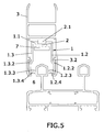
- the device can be installed on the closure side profile and on the upper and lower profile of the movable sheet.
- the hermeticity element (1) has a shaped-U section, presenting a base (1.1) and two walls (1.2, 1.3) intended to embrace the frame profile (6).
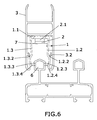
- Such hermeticity element (1) can consist of a single body, according to the embodiment example showed in figures 5 to 8 , or can consist, according to the embodiment example showed in figures 1 to 4 , of three independent pieces, two side walls (1.2, 1.3) are joined to the base (1.1) by introducing their ends (1.2.1, 1.3.1) into a channel (4) of the base (1.1), such ends (1.2.1, 1.3.1) being preferably fixed through clips.
- Each one of these two side walls includes a flap wherewith the hermeticity of the closure is obtained.
- Each one includes a flap (1.2.3, 1.3.3) intended to come into contact with the frame profile (6) for the hermetic closure. Additionally they can comprise another pair of flaps (1.2.4, 1.3.4).
- the base (1.1) of the hermeticity element (1) presents windows (1.4) wherein some tabs (2.1) of the flat bar (2) are housed and between which another hole (1.5) is made.
- the tabs (2.1) are tilted with respect to the flat bar (2). In this way, when longitudinally sliding the flat bar (2) over the profile (3) of the movable sheet the hermeticity element (1) slides over the tabs (2.1) of the flat bar (2) distancing from or approaching to it (2), that is, varying the relative position between both elements (1, 2).
- the actuator mechanism of the hermeticity element (1) is then characterized, in the embodiment examples, by presenting a flat bar (2) that directly acts on the base (1.1) of the hermeticity element (1).
- Such flat bar (2) presents a series of flaps (2.1) distributed into pairs. These flaps (2.1) come up with a certain tilting from one of the faces of the flat bar (2), initially presenting a curved section.
- a slide bar (5) of certain length is made in the flat bar (2) and between the pairs of flaps (2.1).
- This slide bar (5) is complemented with the hole (1.5), not showed in the embodiment corresponding to figures 5 to 8 , of the base (1.1) of the hermeticity element (1) since a pin will be inserted therein which is fixed to the base (1.1) sliding over the slide bar (5) of the flat bar (2).
- the profile (3) of the movable sheet comprises pushing means for the walls (1.2, 1.3) of the hermeticity element (1) in the housing of the hermeticity element (1).
- the profile (3) presents some flaps (3.2) made on both inner faces of its side walls (1.2, 1.3). Their functions are several:
- the device object of the invention Before actuating the lever for closing the door and the hermeticity element (1), the device object of the invention will be in the position depicted in figures 1 , 2 and 5 .
- the flat bar (2) is separated in a distance (x) from the base (1.1) of the hermeticity element (1), wherein the flaps (2.1) of the flat bar (2) come into contact with the base (1.1) through the windows (1.4).
- the initial curve presented by such flaps (2.1) is what causes, with very little displacement of the flat bar (2), the distance of the base (1.1) from the flat bar (2).
- the hermeticity element (1) When the user actuates the lever, he/she will close the door and the hermetic system object of the invention.
- the closure of the hermeticity element (1) will be caused displacing of the flat bar (2) so that its curved sections will be released from the windows (1.4) of the base (1.1) and then will be the posterior face of such flaps (2.1) which presses the base (1.1) of the hermeticity element by approaching it up to come into contact with the flat bar (2).
- This movement is complemented with the flaps (3.2) presented by the profile (3) at its two side walls (1.2, 1.3) and the tilted section presented by them (1.2, 1.3).
- the flaps (3.2) When the base (1.1) approaches to the flat bar (2), the flaps (3.2) come into contact with the tilted section of the side walls (1.2, 1.3) and due to this tilting both walls (1.2, 1.3) approach each other, whereby the aperture of the hermeticity element (1) is closed achieving that the flaps (1.2.3, 1.2.4, 1.3.3, 1.3.4) pressure contact the inner wall (6) of the fixed frame forming the hermetic closure of the system.
- the flaps (3.2) of the profile (3) and the flaps (1.2.2, 1.3.2) of the side walls (1.2, 1.3) of the hermeticity element (1) come into contact forming a second hermetic closure in order to prevent the introduction of foreign particles inside the profile (3) of the movable sheet.
- the user In order to open the hermeticity element (1), the user only has to actuate the lever in the rotating direction opposite to that of the closure, wherewith the flat bar (2) will be displaced approaching the flaps (2.1) to one of the sides of the windows (1.4) of the base (1.1). This approaching will cause that the curved section of the anterior face of such flaps (2.1) acts on the base (1.1) thus distancing it from the flat bar (2) creating the separation distance (x).
- the movement for separating the base (1.1) from the flat bar (2) will form the separation of the flaps (3.2) of the profile (3) of the movable sheet from the flaps (1.2.2, 1.3.2) of the side walls (1.2, 1.3) of the hermeticity element and furthermore the tilted section of such walls complemented with the flaps (3.2) will cause the distance between the walls (1.2 and 1.3), forming the aperture of the hermetic closure.
- the hermeticity element (1) will be plastic.
- the plastic has a deformation which will tend to be plastic with the repetitive use of the aperture and closure of the system, which would prevent the correct function of the system.
- the repetitive bending of the plastic would probably carry its breakage and it is by these two reasons that the bending point of both walls of the hermeticity element has been physically materialized into rubber.
- the flaps of the side walls (1.2, 1.3) of the hermeticity element (1) are also made of rubber, being perfectly adapted to the surface wherewith will come into pressure contact.
- the device comprises supporting means for the flat bar (2) so that the flat bar (2) can perform the longitudinal displacement relative to the profile (3) of the movable sheet.
- the supporting means comprise a guide (3.1) in the profile (3) of the movable sheet that allows the longitudinal sliding in both directions.
- the supporting means comprise a second flat bar (7) that is joined to profile (3) of the movable sheet.
- the joining means consist of a pin which through the slide bar (5) crosses the flat bar (2) and the base (1.1) of the hermeticity element (1) through the hole (1.5) of the base (1.1). The length of such slide bar (5) meets the desired length of the flat bar (2) displacement.
- the second embodiment further presents the advantage of having a greater mounting easiness since in the first solution, the flat bar (2) has to be introduced into the guide (3.1) of the profile (3) of the movable sheet from one of the ends and before assembling the whole frame, and in the second embodiment its introduction into the profile (3) of the movable sheet is frontally performed from outside and can be performed once the whole frame of the movable sheet is assembled.
- the last finish is different in both embodiments, as shown in the attached figures.
- the hermeticity joint (1) and the holes made at its base (1.1) are observed, whereas in the second embodiment only the walls of hermeticity joint (1) and the flat bar (7) having a width covering almost all the base (1.1) of the hermeticity joint (1) are seen, whereby the device presents a better finish.
- the hermeticity element (1) and the flaps (2.1) of the flat bar (2) protruding from the windows (1.4) of the base (1.1) are observed.
- the flat bar (2) is placed at the posterior part of the hermeticity element (1), housed into its corresponding guide (3.1).
- the second embodiment of the device consists of placing the flat bar (2) facing the anterior part of the hermeticity element (1), such flat bar (2) being housed in the inner channel of such element (1).
- the flaps (2.1) are located inside the windows (1.4) of the base (1.1) in a resting position.
- the flat bar (2) will be displaced in a direction and its flaps (2.1) will go back to their respective windows so that when coming into contact with the base (1.1), they will press it causing its approach to the flat bar (2) and consequently the approach between the walls (1.2 and 1.3) of the hermeticity element thus obtaining the hermetic closure of the system.
- the flat bar (2) as well as the hermeticity element (1) can occupy the highest part of the profile length of the movable sheet, leaving a clearance at its ends for allowing the sliding in both directions of the flat bar (2).
Landscapes
- Engineering & Computer Science (AREA)
- Civil Engineering (AREA)
- Structural Engineering (AREA)
- Specific Sealing Or Ventilating Devices For Doors And Windows (AREA)
- Wing Frames And Configurations (AREA)
Applications Claiming Priority (1)
| Application Number | Priority Date | Filing Date | Title |
|---|---|---|---|
| ES200901173U ES1070983Y (es) | 2009-07-24 | 2009-07-24 | Dispositivo de cierre hermetico para puertas y ventanas correderas |
Publications (2)
| Publication Number | Publication Date |
|---|---|
| EP2287434A2 true EP2287434A2 (de) | 2011-02-23 |
| EP2287434A3 EP2287434A3 (de) | 2012-10-03 |
Family
ID=41297168
Family Applications (1)
| Application Number | Title | Priority Date | Filing Date |
|---|---|---|---|
| EP10382182A Withdrawn EP2287434A3 (de) | 2009-07-24 | 2010-06-25 | Hermetische Verschlussvorrichtung für Schiebetüren und -fenster |
Country Status (2)
| Country | Link |
|---|---|
| EP (1) | EP2287434A3 (de) |
| ES (1) | ES1070983Y (de) |
Cited By (2)
| Publication number | Priority date | Publication date | Assignee | Title |
|---|---|---|---|---|
| WO2014032141A1 (pt) * | 2012-08-27 | 2014-03-06 | Gadioli Fabio | Sistema de acionamento para obtenção de vedação hermética e acústica em es uadrias deslizantes |
| AT517004A3 (de) * | 2015-04-08 | 2017-05-15 | Athmer Ohg | Dichtleistengehäuse eines Türdichtungssystems |
Family Cites Families (1)
| Publication number | Priority date | Publication date | Assignee | Title |
|---|---|---|---|---|
| GB2454534B (en) * | 2007-11-12 | 2009-12-16 | Muskita Aluminium Ind Plc | Sealing system for a movable panel and a panel for use with such a system |
-
2009
- 2009-07-24 ES ES200901173U patent/ES1070983Y/es not_active Expired - Lifetime
-
2010
- 2010-06-25 EP EP10382182A patent/EP2287434A3/de not_active Withdrawn
Non-Patent Citations (1)
| Title |
|---|
| None |
Cited By (3)
| Publication number | Priority date | Publication date | Assignee | Title |
|---|---|---|---|---|
| WO2014032141A1 (pt) * | 2012-08-27 | 2014-03-06 | Gadioli Fabio | Sistema de acionamento para obtenção de vedação hermética e acústica em es uadrias deslizantes |
| AT517004A3 (de) * | 2015-04-08 | 2017-05-15 | Athmer Ohg | Dichtleistengehäuse eines Türdichtungssystems |
| AT517004B1 (de) * | 2015-04-08 | 2017-09-15 | Athmer Ohg | Dichtleistengehäuse eines Türdichtungssystems |
Also Published As
| Publication number | Publication date |
|---|---|
| ES1070983U (es) | 2009-11-30 |
| ES1070983Y (es) | 2010-03-01 |
| EP2287434A3 (de) | 2012-10-03 |
Similar Documents
| Publication | Publication Date | Title |
|---|---|---|
| EP3289158B1 (de) | Scharnier für möbelblätter, die um mindestens eine horizontale achse schwenken | |
| KR20170072334A (ko) | 씰링 장치 | |
| JP5952970B2 (ja) | 引戸クローザーセット | |
| WO2013191622A1 (en) | Connecting device for releasably connecting a first element to a second element | |
| KR102050670B1 (ko) | 슬라이딩 창호용 레일 스토퍼 | |
| EP2287434A2 (de) | Hermetische Verschlussvorrichtung für Schiebetüren und -fenster | |
| HUP0302865A2 (hu) | Tömítés különösen hűtőgépszekrény egységekhez | |
| WO2005098174A3 (de) | Fenster oder tür mit elektromechanischer verriegelung | |
| EP1764469B1 (de) | Motorisch angetriebene Fenstereinheit mit schwenkbarer Öffnung | |
| EP3498940A1 (de) | Griffelement zur aufnahme in der frontseite einer tür eines schranks, insbesondere schaltschranks | |
| KR102153572B1 (ko) | 레일 은폐형 창호 | |
| EP2055532A1 (de) | Handschuhfach eines Kraftfahrzeugs mit einer Tür mit verstellbarer Verschlussposition | |
| EP1736623A3 (de) | Türsicherheitssystem | |
| EP3438404B1 (de) | Dichtungsvorrichtung für fenster oder tür ohne schwelle | |
| JP2020527204A (ja) | ドロップダウンシール | |
| KR20160009255A (ko) | 3단 미닫이문 연동장치 | |
| KR101697763B1 (ko) | 엘리베이터의 도어실 구조 | |
| US10267076B2 (en) | Connecting device and window or door comprising a connecting device | |
| EP1619060A2 (de) | Dichtung zwischen Fahrzeugkarrosseriebauteilen | |
| EP1781886B1 (de) | Verbessertes rollmoskitonetz mit faltführungen | |
| EP1728946A1 (de) | Verschluss mit Treibstange für Fenster und/oder Türen | |
| WO2003051156A1 (en) | Sliding guide, closing block and method for assembling a sliding guide | |
| EP1048814A1 (de) | Eine Tür, ein Türblatt und ein Türschliessverfahren | |
| EP1250866A1 (de) | Führungsmittel zur Montage zwischen zwei Bauteilen eines teleskopischen Beines | |
| EP1579098A1 (de) | Zugluftstoppervorrichtung, insbesondere für türen unddergleichen |
Legal Events
| Date | Code | Title | Description |
|---|---|---|---|
| PUAI | Public reference made under article 153(3) epc to a published international application that has entered the european phase |
Free format text: ORIGINAL CODE: 0009012 |
|
| AK | Designated contracting states |
Kind code of ref document: A2 Designated state(s): AL AT BE BG CH CY CZ DE DK EE ES FI FR GB GR HR HU IE IS IT LI LT LU LV MC MK MT NL NO PL PT RO SE SI SK SM TR |
|
| AX | Request for extension of the european patent |
Extension state: BA ME RS |
|
| RIC1 | Information provided on ipc code assigned before grant |
Ipc: E06B 7/215 20060101AFI20120628BHEP Ipc: E06B 3/46 20060101ALN20120628BHEP |
|
| PUAL | Search report despatched |
Free format text: ORIGINAL CODE: 0009013 |
|
| AK | Designated contracting states |
Kind code of ref document: A3 Designated state(s): AL AT BE BG CH CY CZ DE DK EE ES FI FR GB GR HR HU IE IS IT LI LT LU LV MC MK MT NL NO PL PT RO SE SI SK SM TR |
|
| AX | Request for extension of the european patent |
Extension state: BA ME RS |
|
| STAA | Information on the status of an ep patent application or granted ep patent |
Free format text: STATUS: THE APPLICATION IS DEEMED TO BE WITHDRAWN |
|
| 18D | Application deemed to be withdrawn |
Effective date: 20130404 |