EP2287468A1 - Unité de dosage - Google Patents
Unité de dosage Download PDFInfo
- Publication number
- EP2287468A1 EP2287468A1 EP20100007505 EP10007505A EP2287468A1 EP 2287468 A1 EP2287468 A1 EP 2287468A1 EP 20100007505 EP20100007505 EP 20100007505 EP 10007505 A EP10007505 A EP 10007505A EP 2287468 A1 EP2287468 A1 EP 2287468A1
- Authority
- EP
- European Patent Office
- Prior art keywords
- pump
- dosing unit
- valves
- fluid housing
- valve
- Prior art date
- Legal status (The legal status is an assumption and is not a legal conclusion. Google has not performed a legal analysis and makes no representation as to the accuracy of the status listed.)
- Granted
Links
Images



Classifications
-
- F—MECHANICAL ENGINEERING; LIGHTING; HEATING; WEAPONS; BLASTING
- F04—POSITIVE - DISPLACEMENT MACHINES FOR LIQUIDS; PUMPS FOR LIQUIDS OR ELASTIC FLUIDS
- F04B—POSITIVE-DISPLACEMENT MACHINES FOR LIQUIDS; PUMPS
- F04B43/00—Machines, pumps, or pumping installations having flexible working members
- F04B43/02—Machines, pumps, or pumping installations having flexible working members having plate-like flexible members, e.g. diaphragms
- F04B43/04—Pumps having electric drive
- F04B43/043—Micropumps
-
- F—MECHANICAL ENGINEERING; LIGHTING; HEATING; WEAPONS; BLASTING
- F04—POSITIVE - DISPLACEMENT MACHINES FOR LIQUIDS; PUMPS FOR LIQUIDS OR ELASTIC FLUIDS
- F04B—POSITIVE-DISPLACEMENT MACHINES FOR LIQUIDS; PUMPS
- F04B19/00—Machines or pumps having pertinent characteristics not provided for in, or of interest apart from, groups F04B1/00 - F04B17/00
- F04B19/006—Micropumps
-
- G—PHYSICS
- G01—MEASURING; TESTING
- G01F—MEASURING VOLUME, VOLUME FLOW, MASS FLOW OR LIQUID LEVEL; METERING BY VOLUME
- G01F11/00—Apparatus requiring external operation adapted at each repeated and identical operation to measure and separate a predetermined volume of fluid or fluent solid material from a supply or container, without regard to weight, and to deliver it
- G01F11/02—Apparatus requiring external operation adapted at each repeated and identical operation to measure and separate a predetermined volume of fluid or fluent solid material from a supply or container, without regard to weight, and to deliver it with measuring chambers which expand or contract during measurement
- G01F11/08—Apparatus requiring external operation adapted at each repeated and identical operation to measure and separate a predetermined volume of fluid or fluent solid material from a supply or container, without regard to weight, and to deliver it with measuring chambers which expand or contract during measurement of the diaphragm or bellows type
-
- Y—GENERAL TAGGING OF NEW TECHNOLOGICAL DEVELOPMENTS; GENERAL TAGGING OF CROSS-SECTIONAL TECHNOLOGIES SPANNING OVER SEVERAL SECTIONS OF THE IPC; TECHNICAL SUBJECTS COVERED BY FORMER USPC CROSS-REFERENCE ART COLLECTIONS [XRACs] AND DIGESTS
- Y10—TECHNICAL SUBJECTS COVERED BY FORMER USPC
- Y10T—TECHNICAL SUBJECTS COVERED BY FORMER US CLASSIFICATION
- Y10T137/00—Fluid handling
- Y10T137/8593—Systems
- Y10T137/85978—With pump
- Y10T137/85986—Pumped fluid control
Definitions
- the invention relates to a metering unit for the precise metering of small amounts of liquid or gas in the ⁇ l range, which is essentially composed of a fluid housing, a pump and two valves. Furthermore, the invention relates to a method for operating the dosing unit.
- Syringe pumps, diaphragm pumps or peristaltic pumps are usually used for the precise dosing of predominantly aggressive media. Depending on the design, these pumps have disadvantages for certain applications: because of the required electronic control, syringe pumps are expensive and can not convey continuously. Peristaltic pumps and diaphragm pumps are too inaccurate for precise dosages; In addition, diaphragm pumps can only deliver in one direction and can not close the fluid tight against back pressure.
- a metering unit can be promoted with the medium in two directions, and which is composed essentially of a fluid housing, a pump and two valves.
- Such a dosing unit is offered, for example, by the company Bürkert as micro dosing unit type 7616.
- the pump is arranged on one side of the fluid housing, which cooperates with a lying on the same side of the fluid housing pump chamber.
- the two valves are arranged on the opposite side of the fluid housing.
- the pump is connected to the two valves via fluid passages, which are guided from a fluid housing side to the fluid housing side opposite thereto through the fluid housing.
- the metering unit according to the invention is characterized by an extremely space-saving and compact design, which is achieved in that the pump and both valves are arranged side by side on the same side of the fluid housing.
- Pump passages Fluid passages interconnecting the pumping chamber and a valve are hereafter referred to as "pump passages", and fluid passages extending between a port of the dosing unit and a valve are referred to as "valve passages".
- two pump channels which initially protrude through the fluid housing as well as in the prior art, continue from the pump chamber on the opposite side to the valve ports on the opposite side, and from there back again the fluid housing through to a valve.
- the valve channels which protrude through the fluid housing, from the valves on the side opposite to this side continue to the two terminals of the metering unit.
- the fluid channels are sealed with a flat gasket and end plate. This type of ducting allows the pump and the two valves to be placed on the same side.
- the fluid housing is formed substantially cuboid.
- the pump and both valves are arranged side by side and on a perpendicular side surface, the two terminals of the dosing unit, whereby they are easily accessible to the user.
- the fluid housing with a lid mounted thereon and fixedly connected thereto forms a compact unit in which all components such as the pump and valves as well as a control electronics are arranged.
- the dosing unit is robust against external influences and the devices lying in the lid are protected.
- the two fluidic connections of the metering unit are arranged in the fluid housing within two adjacent pedestals which protrude through recesses of a flange plate, which is fastened to the fluid housing, for example by means of screws.
- a flange plate which is fastened to the fluid housing, for example by means of screws.
- the Flange plate holes are provided by means of which the flange plate can be mounted on an external connection plate.
- a threaded plate is connected to the fluid housing, in whose passing therethrough recesses protrude the two pedestals, and having on its side facing away from the fluid housing side within the recesses threaded for screwing hose connectors.
- This geometry and design of the dosing unit connections as a base formed on the fluid housing allows flexible coupling to flange or threaded plates.
- the pump includes a coupling element which is configured as a two-armed, mounted and pivotable lever and which is connected to a membrane.
- the coupling element experiences its motive force in a known manner, for example by a magnetic drive.
- a first lever arm can release and close the pump chamber and a second cooperates with the set screw, thereby defining the pump stroke.
- predefined pumping cycles are retrieved, each of which successively comprises a first phase in which the input-side valve opens and closes, a second phase in which a pumping stroke takes place, and a third phase in which the output side valve opens and closes again, wherein the first phase overlaps with the second phase and overlaps the third phase with the second phase.
- Calibration is done by adjusting the size of the pump stroke. For a precise measurement of the volume or weight of the pumped medium per pump stroke, a predetermined number of pump cycles are carried out, e.g. one hundred, and the volume delivered divided by the number of cycles. Alternatively, calibration is accomplished by adjusting the number of pump cycles needed to obtain a defined weight of metered medium. In any case, then the metered volume is independent of manufacturing tolerances of the device, or they can be compensated, and the fluid housing can be conveniently manufactured by injection molding.
- the metering unit is a generally cuboidal device.
- a cover 10 which can also be referred to as a hood, is placed on a fluid body 12 and encloses all components of the dosing unit.
- a flange plate 14 bolted.
- a connector 16 with three contacts is accessible on a side surface of the lid 10.
- the execution in FIG. 2 is different from the after FIG. 1 only by a threaded plate 14 a, which is screwed in place of the flange plate 14.
- FIG. 3 the dosing unit turned upside down.
- a first valve 18, a pump 20 and a second valve 22 are placed side by side.
- the fluid housing 12 has the shape of a flat cuboid.
- a closure plate 28 closes the main side of the fluid body 12 remote from the valves and the pump, which has threaded holes for fastening screws at its corners, with which the entire structure is held together.
- An adjusting screw 30 runs in a fine thread of a threaded bore 30a of the end plate 28 and extends through a bore 30b in Fluid housing 12.
- An electronic assembly 32 which is shown here only schematically as a plate, has connectors 34 for the valves 18, 22 and the pump 20 and the externally accessible connector 16th
- FIG. 4 is the section laid by the pump and the fluid housing.
- the pump is a diaphragm pump.
- the diaphragm of the pump cooperates with a pump chamber 40 formed on an adjacent major surface of the fluid body 12.
- the membrane is connected to an arm of a two-armed actuator 42, which forms a rocker and is pivotally mounted on an axle 44. On the second arm of the actuator 42 engages one end of the adjusting screw 30.
- two transverse bores 46, 48 of the fluid body 12 can be seen.
- two channels 50, 52 open into the pumping chamber 40.
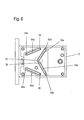
- These channels 50, 52 pass through the fluid body 12 and terminate in the in FIG. 6 shown bottom. There, they pass into channel sections 50a, 52a, which in turn terminate at channels 50b, 52b, which pass through the fluid body 12 and lead to one of the two valves 18, 22 on the opposite main side of the fluid body 12.
- Of the valves 18, 22 lead two further fluid channels 54, 56 transversely through the fluid body 12 and go into channel sections 54 a and 56 a on the opposite major surface of the fluid body 12 over.
- These channel sections 54a, 56a terminate at fluid channels 54b, 56b leading to the terminals of the flange plate 14 and threaded plate 14a, respectively.
- the dosing unit is completely symmetrical and can therefore be operated in two opposite flow directions.
- the two fluidic connections on the flange plate 14 or threaded plate 14a can be operated both as an inlet and as an outlet.
- the direction of flow is determined by the sequence of actuation of the valves 18, 22.
- the pump stroke of the diaphragm pump is adjusted.
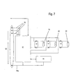
- FIG. 7 is very schematically shown the control electronics of the dosing.
- the electronics package 32 which may include a microcontroller and associated control software, has ports 70, 72 for the two valves 18, 22 and a port 74 for the pump 20.
- Sensors 76 may also be connected to the electronics package 32.
- the three contacts of the connector 16 correspond to three control lines 78, which are connected to inputs of the electronic assembly 32.
- the reference potential is supplied to the electronics assembly 32 and the sensors 76 via another line 78a. Between the line 78a and each of the lines 78, the operating voltage U is further supplied.
- the dosing unit is preferably operated in single or sequential pumping cycles, all of which are the same.
- a pumping cycle is, for example, in FIG. 8 shown.
- solid line is in FIG. 8 the application of the operating voltage U to one of the control lines 78 from time T A to T E shown as a solid line.
- dash-dotted is in FIG. 8 the switch-on function of the output-side valve in FIG. 8 shown. It opens at time T 4 .
- the pump has completed its ejection stroke.
- the output side valve closes at time T 6 . It can therefore be seen that the opening times of the valves overlap with the function of the pump.
- the third of the control lines 78 can be used to hold both valves open by applying the operating voltage U and lift the membrane of the diaphragm pump from the pump chamber, so that the entire dosing unit can be flushed through.
- the preferred method is to set the volume delivered with each individual pump stroke by means of the adjusting screw 30 to a desired value.
- a certain number of pump cycles are performed, for example, one hundred.
- the measured total volume is then divided by the number of pump cycles.
- the volume measurement can be done by weight determination.
- the volume delivered per pump cycle is optionally adjusted stepwise to the desired value, for example 5 ⁇ l.
- Another method is to determine the number of pump cycles needed to deliver a given volume, which may be measured again by weight. The volume is then divided by the number of pump cycles needed and gives the volume delivered per pump cycle.
- the dosing unit is preferably controlled by software.
- the dosing unit can be coupled with various sensors to detect operating variables.
- the electronic module can be equipped with an interface via which a parameterization of all control functions of the dosing unit can take place.
- the drives of the valves and pump can be over-excited for a short time. In combination with it or separately, the drives can be operated with reduced power to save energy.
Landscapes
- Engineering & Computer Science (AREA)
- Mechanical Engineering (AREA)
- General Engineering & Computer Science (AREA)
- Physics & Mathematics (AREA)
- Fluid Mechanics (AREA)
- General Physics & Mathematics (AREA)
- Reciprocating Pumps (AREA)
Applications Claiming Priority (1)
| Application Number | Priority Date | Filing Date | Title |
|---|---|---|---|
| DE102009038492A DE102009038492A1 (de) | 2009-08-21 | 2009-08-21 | Dosiereinheit |
Publications (2)
| Publication Number | Publication Date |
|---|---|
| EP2287468A1 true EP2287468A1 (fr) | 2011-02-23 |
| EP2287468B1 EP2287468B1 (fr) | 2017-03-01 |
Family
ID=42813490
Family Applications (1)
| Application Number | Title | Priority Date | Filing Date |
|---|---|---|---|
| EP10007505.0A Active EP2287468B1 (fr) | 2009-08-21 | 2010-07-20 | Unité de dosage |
Country Status (3)
| Country | Link |
|---|---|
| US (1) | US8556597B2 (fr) |
| EP (1) | EP2287468B1 (fr) |
| DE (1) | DE102009038492A1 (fr) |
Cited By (1)
| Publication number | Priority date | Publication date | Assignee | Title |
|---|---|---|---|---|
| DE202013105592U1 (de) | 2013-12-09 | 2014-01-14 | Bürkert Werke GmbH | Dosiereinheit |
Citations (4)
| Publication number | Priority date | Publication date | Assignee | Title |
|---|---|---|---|---|
| US4047844A (en) * | 1975-12-08 | 1977-09-13 | Searle Cardio-Pulmonary Systems Inc. | Blood pumping system |
| WO2004090334A1 (fr) * | 2003-04-10 | 2004-10-21 | Bayer Industry Services Gmbh & | Pompe a membrane |
| DE102008042071A1 (de) * | 2007-09-12 | 2009-03-19 | Gernot Heuser | Mikrodosierpumpe |
| WO2009059664A1 (fr) * | 2007-11-05 | 2009-05-14 | Bartels Mikrotechnik Gmbh | Procédé pour la circulation d'un fluide, et micropompe utilisée à cet effet |
Family Cites Families (11)
| Publication number | Priority date | Publication date | Assignee | Title |
|---|---|---|---|---|
| JPS5749747B2 (fr) * | 1975-03-20 | 1982-10-23 | ||
| DE20009234U1 (de) * | 2000-05-23 | 2000-08-24 | Bürkert Werke GmbH & Co., 74653 Ingelfingen | Fluidisches Anschlusssystem |
| US6550496B2 (en) * | 2001-01-16 | 2003-04-22 | General Electric Company | Rotary doser valve |
| WO2005070816A1 (fr) * | 2004-01-21 | 2005-08-04 | Imi Vision Limited | Distributeur de boissons |
| US8449267B2 (en) * | 2004-09-29 | 2013-05-28 | Shurflo, Llc | Pump assembly and fluid metering unit |
| US7717682B2 (en) * | 2005-07-13 | 2010-05-18 | Purity Solutions Llc | Double diaphragm pump and related methods |
| DE102005058080B4 (de) * | 2005-12-06 | 2008-01-03 | Albert-Ludwigs-Universität Freiburg | Überwachungseinheit zur Fluiddosierung und Mikrodosieranordnung |
| JP2007291857A (ja) * | 2006-04-20 | 2007-11-08 | Nidec Sankyo Corp | 定量ポンプ装置 |
| EP1909077A1 (fr) * | 2006-10-02 | 2008-04-09 | Syngeta Participations AG | Appareil de dosage pour liquides |
| DE202007003999U1 (de) * | 2007-03-14 | 2008-07-17 | ECOLAB, INC., St. Paul | Mehrfach-Dosiereinrichtung |
| DE202007007927U1 (de) * | 2007-06-05 | 2007-08-23 | Bürkert Werke GmbH & Co. KG | Hybrides Universalverteilersystem mit elektrischen, fluidischen und Kommunikationsfunktionen |
-
2009
- 2009-08-21 DE DE102009038492A patent/DE102009038492A1/de not_active Withdrawn
-
2010
- 2010-07-20 EP EP10007505.0A patent/EP2287468B1/fr active Active
- 2010-08-18 US US12/858,450 patent/US8556597B2/en active Active
Patent Citations (4)
| Publication number | Priority date | Publication date | Assignee | Title |
|---|---|---|---|---|
| US4047844A (en) * | 1975-12-08 | 1977-09-13 | Searle Cardio-Pulmonary Systems Inc. | Blood pumping system |
| WO2004090334A1 (fr) * | 2003-04-10 | 2004-10-21 | Bayer Industry Services Gmbh & | Pompe a membrane |
| DE102008042071A1 (de) * | 2007-09-12 | 2009-03-19 | Gernot Heuser | Mikrodosierpumpe |
| WO2009059664A1 (fr) * | 2007-11-05 | 2009-05-14 | Bartels Mikrotechnik Gmbh | Procédé pour la circulation d'un fluide, et micropompe utilisée à cet effet |
Non-Patent Citations (1)
| Title |
|---|
| "Micro-Dosiereinheit Typ 7616", 5 June 2009 (2009-06-05), XP002613036, Retrieved from the Internet <URL:http://www.buerkert.com/products_data/manuals/MA7616-Dosingunit-EU-ML.pdf> [retrieved on 20101207] * |
Cited By (2)
| Publication number | Priority date | Publication date | Assignee | Title |
|---|---|---|---|---|
| DE202013105592U1 (de) | 2013-12-09 | 2014-01-14 | Bürkert Werke GmbH | Dosiereinheit |
| DE102014118218A1 (de) | 2013-12-09 | 2015-06-11 | Bürkert Werke GmbH | Dosiereinheit |
Also Published As
| Publication number | Publication date |
|---|---|
| US20110041936A1 (en) | 2011-02-24 |
| DE102009038492A1 (de) | 2011-02-24 |
| EP2287468B1 (fr) | 2017-03-01 |
| US8556597B2 (en) | 2013-10-15 |
Similar Documents
| Publication | Publication Date | Title |
|---|---|---|
| EP2222959B1 (fr) | Procédé pour la circulation d'un fluide, et micropompe utilisée à cet effet | |
| EP0484278B1 (fr) | Appareil de préparation d'échantillons liquides pour l'analyse chimique | |
| DE102017125761A1 (de) | Elektromagnetisches Ventil | |
| DE112010005186B4 (de) | Fluidsteuervorrichtung und Volumenstromregelungseinrichtung | |
| DE10239597B4 (de) | Einwegkassette | |
| DE102008045524A1 (de) | Verfahren zur autonomen Steuerung eines Chemikalien-Einspritzsystems für Öl- und Gas-Bohrlöcher | |
| EP2470915B1 (fr) | Système d'analyse modulaire par injection en flux continu | |
| DE3722763C2 (fr) | ||
| DE112019000772T5 (de) | Elektronisches ventil, sphygmomanometer und gerät | |
| DE102006019997B4 (de) | Saug- und Saugabschalt-Verbundventil | |
| EP2287468B1 (fr) | Unité de dosage | |
| EP2191135A1 (fr) | Système de microdosage | |
| DE102018200680B4 (de) | Drucküberwachungsvorrichtung und damit ausgestattete Ventilanordnung | |
| DE112015001329T5 (de) | Mehrwege-Dosierpumpenanordnung und zugehörige Verfahren | |
| DE10316395B4 (de) | Membranpumpe | |
| DE60125193T2 (de) | Modulare anordnung von zweiwegerückschlagventil | |
| WO1998025110A1 (fr) | Dispositif de reduction d'ecoulement produit selon un procede micromecanique | |
| DE19650116C1 (de) | Mikromechanisch gefertigte Flußrestriktionsvorrichtung | |
| EP3714822B1 (fr) | Dispositif de commande de fluide pour un appareil médical | |
| DE102023119300A1 (de) | Fluidgerät | |
| DE19545021A1 (de) | Elektromagnetisch betätigtes Wegeventil | |
| DE3421082A1 (de) | Piezoelektrisches foerder- und dosiergeraet | |
| WO1997012150A1 (fr) | Distributeur a actionnement electromagnetique | |
| WO2010118808A1 (fr) | Dispositif à soupapes | |
| DE10134199C1 (de) | Stromregelventilanordnung |
Legal Events
| Date | Code | Title | Description |
|---|---|---|---|
| PUAI | Public reference made under article 153(3) epc to a published international application that has entered the european phase |
Free format text: ORIGINAL CODE: 0009012 |
|
| AK | Designated contracting states |
Kind code of ref document: A1 Designated state(s): AL AT BE BG CH CY CZ DE DK EE ES FI FR GB GR HR HU IE IS IT LI LT LU LV MC MK MT NL NO PL PT RO SE SI SK SM TR |
|
| AX | Request for extension of the european patent |
Extension state: BA ME RS |
|
| 17P | Request for examination filed |
Effective date: 20110822 |
|
| REG | Reference to a national code |
Ref country code: DE Ref legal event code: R079 Ref document number: 502010013220 Country of ref document: DE Free format text: PREVIOUS MAIN CLASS: F04B0043000000 Ipc: F04B0019000000 |
|
| RIC1 | Information provided on ipc code assigned before grant |
Ipc: F04B 43/04 20060101ALI20160711BHEP Ipc: G01F 11/08 20060101ALI20160711BHEP Ipc: F04B 19/00 20060101AFI20160711BHEP |
|
| GRAP | Despatch of communication of intention to grant a patent |
Free format text: ORIGINAL CODE: EPIDOSNIGR1 |
|
| INTG | Intention to grant announced |
Effective date: 20160916 |
|
| GRAS | Grant fee paid |
Free format text: ORIGINAL CODE: EPIDOSNIGR3 |
|
| GRAA | (expected) grant |
Free format text: ORIGINAL CODE: 0009210 |
|
| AK | Designated contracting states |
Kind code of ref document: B1 Designated state(s): AL AT BE BG CH CY CZ DE DK EE ES FI FR GB GR HR HU IE IS IT LI LT LU LV MC MK MT NL NO PL PT RO SE SI SK SM TR |
|
| REG | Reference to a national code |
Ref country code: GB Ref legal event code: FG4D Free format text: NOT ENGLISH |
|
| REG | Reference to a national code |
Ref country code: CH Ref legal event code: EP Ref country code: AT Ref legal event code: REF Ref document number: 871702 Country of ref document: AT Kind code of ref document: T Effective date: 20170315 |
|
| REG | Reference to a national code |
Ref country code: IE Ref legal event code: FG4D Free format text: LANGUAGE OF EP DOCUMENT: GERMAN |
|
| REG | Reference to a national code |
Ref country code: DE Ref legal event code: R096 Ref document number: 502010013220 Country of ref document: DE |
|
| REG | Reference to a national code |
Ref country code: NL Ref legal event code: MP Effective date: 20170301 |
|
| REG | Reference to a national code |
Ref country code: LT Ref legal event code: MG4D |
|
| PG25 | Lapsed in a contracting state [announced via postgrant information from national office to epo] |
Ref country code: LT Free format text: LAPSE BECAUSE OF FAILURE TO SUBMIT A TRANSLATION OF THE DESCRIPTION OR TO PAY THE FEE WITHIN THE PRESCRIBED TIME-LIMIT Effective date: 20170301 Ref country code: HR Free format text: LAPSE BECAUSE OF FAILURE TO SUBMIT A TRANSLATION OF THE DESCRIPTION OR TO PAY THE FEE WITHIN THE PRESCRIBED TIME-LIMIT Effective date: 20170301 Ref country code: GR Free format text: LAPSE BECAUSE OF FAILURE TO SUBMIT A TRANSLATION OF THE DESCRIPTION OR TO PAY THE FEE WITHIN THE PRESCRIBED TIME-LIMIT Effective date: 20170602 Ref country code: FI Free format text: LAPSE BECAUSE OF FAILURE TO SUBMIT A TRANSLATION OF THE DESCRIPTION OR TO PAY THE FEE WITHIN THE PRESCRIBED TIME-LIMIT Effective date: 20170301 Ref country code: NO Free format text: LAPSE BECAUSE OF FAILURE TO SUBMIT A TRANSLATION OF THE DESCRIPTION OR TO PAY THE FEE WITHIN THE PRESCRIBED TIME-LIMIT Effective date: 20170601 |
|
| PG25 | Lapsed in a contracting state [announced via postgrant information from national office to epo] |
Ref country code: ES Free format text: LAPSE BECAUSE OF FAILURE TO SUBMIT A TRANSLATION OF THE DESCRIPTION OR TO PAY THE FEE WITHIN THE PRESCRIBED TIME-LIMIT Effective date: 20170301 Ref country code: BG Free format text: LAPSE BECAUSE OF FAILURE TO SUBMIT A TRANSLATION OF THE DESCRIPTION OR TO PAY THE FEE WITHIN THE PRESCRIBED TIME-LIMIT Effective date: 20170601 Ref country code: LV Free format text: LAPSE BECAUSE OF FAILURE TO SUBMIT A TRANSLATION OF THE DESCRIPTION OR TO PAY THE FEE WITHIN THE PRESCRIBED TIME-LIMIT Effective date: 20170301 Ref country code: SE Free format text: LAPSE BECAUSE OF FAILURE TO SUBMIT A TRANSLATION OF THE DESCRIPTION OR TO PAY THE FEE WITHIN THE PRESCRIBED TIME-LIMIT Effective date: 20170301 |
|
| PG25 | Lapsed in a contracting state [announced via postgrant information from national office to epo] |
Ref country code: NL Free format text: LAPSE BECAUSE OF FAILURE TO SUBMIT A TRANSLATION OF THE DESCRIPTION OR TO PAY THE FEE WITHIN THE PRESCRIBED TIME-LIMIT Effective date: 20170301 |
|
| PG25 | Lapsed in a contracting state [announced via postgrant information from national office to epo] |
Ref country code: RO Free format text: LAPSE BECAUSE OF FAILURE TO SUBMIT A TRANSLATION OF THE DESCRIPTION OR TO PAY THE FEE WITHIN THE PRESCRIBED TIME-LIMIT Effective date: 20170301 Ref country code: CZ Free format text: LAPSE BECAUSE OF FAILURE TO SUBMIT A TRANSLATION OF THE DESCRIPTION OR TO PAY THE FEE WITHIN THE PRESCRIBED TIME-LIMIT Effective date: 20170301 Ref country code: IT Free format text: LAPSE BECAUSE OF FAILURE TO SUBMIT A TRANSLATION OF THE DESCRIPTION OR TO PAY THE FEE WITHIN THE PRESCRIBED TIME-LIMIT Effective date: 20170301 Ref country code: SK Free format text: LAPSE BECAUSE OF FAILURE TO SUBMIT A TRANSLATION OF THE DESCRIPTION OR TO PAY THE FEE WITHIN THE PRESCRIBED TIME-LIMIT Effective date: 20170301 Ref country code: EE Free format text: LAPSE BECAUSE OF FAILURE TO SUBMIT A TRANSLATION OF THE DESCRIPTION OR TO PAY THE FEE WITHIN THE PRESCRIBED TIME-LIMIT Effective date: 20170301 |
|
| PG25 | Lapsed in a contracting state [announced via postgrant information from national office to epo] |
Ref country code: PL Free format text: LAPSE BECAUSE OF FAILURE TO SUBMIT A TRANSLATION OF THE DESCRIPTION OR TO PAY THE FEE WITHIN THE PRESCRIBED TIME-LIMIT Effective date: 20170301 Ref country code: IS Free format text: LAPSE BECAUSE OF FAILURE TO SUBMIT A TRANSLATION OF THE DESCRIPTION OR TO PAY THE FEE WITHIN THE PRESCRIBED TIME-LIMIT Effective date: 20170701 Ref country code: PT Free format text: LAPSE BECAUSE OF FAILURE TO SUBMIT A TRANSLATION OF THE DESCRIPTION OR TO PAY THE FEE WITHIN THE PRESCRIBED TIME-LIMIT Effective date: 20170703 Ref country code: SM Free format text: LAPSE BECAUSE OF FAILURE TO SUBMIT A TRANSLATION OF THE DESCRIPTION OR TO PAY THE FEE WITHIN THE PRESCRIBED TIME-LIMIT Effective date: 20170301 |
|
| REG | Reference to a national code |
Ref country code: DE Ref legal event code: R097 Ref document number: 502010013220 Country of ref document: DE |
|
| PLBE | No opposition filed within time limit |
Free format text: ORIGINAL CODE: 0009261 |
|
| STAA | Information on the status of an ep patent application or granted ep patent |
Free format text: STATUS: NO OPPOSITION FILED WITHIN TIME LIMIT |
|
| PG25 | Lapsed in a contracting state [announced via postgrant information from national office to epo] |
Ref country code: DK Free format text: LAPSE BECAUSE OF FAILURE TO SUBMIT A TRANSLATION OF THE DESCRIPTION OR TO PAY THE FEE WITHIN THE PRESCRIBED TIME-LIMIT Effective date: 20170301 |
|
| 26N | No opposition filed |
Effective date: 20171204 |
|
| PG25 | Lapsed in a contracting state [announced via postgrant information from national office to epo] |
Ref country code: SI Free format text: LAPSE BECAUSE OF FAILURE TO SUBMIT A TRANSLATION OF THE DESCRIPTION OR TO PAY THE FEE WITHIN THE PRESCRIBED TIME-LIMIT Effective date: 20170301 |
|
| REG | Reference to a national code |
Ref country code: CH Ref legal event code: PL |
|
| GBPC | Gb: european patent ceased through non-payment of renewal fee |
Effective date: 20170720 |
|
| REG | Reference to a national code |
Ref country code: IE Ref legal event code: MM4A |
|
| REG | Reference to a national code |
Ref country code: FR Ref legal event code: ST Effective date: 20180330 |
|
| PG25 | Lapsed in a contracting state [announced via postgrant information from national office to epo] |
Ref country code: IE Free format text: LAPSE BECAUSE OF NON-PAYMENT OF DUE FEES Effective date: 20170720 Ref country code: GB Free format text: LAPSE BECAUSE OF NON-PAYMENT OF DUE FEES Effective date: 20170720 Ref country code: CH Free format text: LAPSE BECAUSE OF NON-PAYMENT OF DUE FEES Effective date: 20170731 Ref country code: LI Free format text: LAPSE BECAUSE OF NON-PAYMENT OF DUE FEES Effective date: 20170731 |
|
| PG25 | Lapsed in a contracting state [announced via postgrant information from national office to epo] |
Ref country code: FR Free format text: LAPSE BECAUSE OF NON-PAYMENT OF DUE FEES Effective date: 20170731 |
|
| REG | Reference to a national code |
Ref country code: BE Ref legal event code: MM Effective date: 20170731 |
|
| PG25 | Lapsed in a contracting state [announced via postgrant information from national office to epo] |
Ref country code: LU Free format text: LAPSE BECAUSE OF NON-PAYMENT OF DUE FEES Effective date: 20170720 |
|
| PG25 | Lapsed in a contracting state [announced via postgrant information from national office to epo] |
Ref country code: BE Free format text: LAPSE BECAUSE OF NON-PAYMENT OF DUE FEES Effective date: 20170731 |
|
| REG | Reference to a national code |
Ref country code: AT Ref legal event code: MM01 Ref document number: 871702 Country of ref document: AT Kind code of ref document: T Effective date: 20170720 |
|
| PG25 | Lapsed in a contracting state [announced via postgrant information from national office to epo] |
Ref country code: MT Free format text: LAPSE BECAUSE OF FAILURE TO SUBMIT A TRANSLATION OF THE DESCRIPTION OR TO PAY THE FEE WITHIN THE PRESCRIBED TIME-LIMIT Effective date: 20170301 |
|
| PG25 | Lapsed in a contracting state [announced via postgrant information from national office to epo] |
Ref country code: AT Free format text: LAPSE BECAUSE OF NON-PAYMENT OF DUE FEES Effective date: 20170720 |
|
| PG25 | Lapsed in a contracting state [announced via postgrant information from national office to epo] |
Ref country code: HU Free format text: LAPSE BECAUSE OF FAILURE TO SUBMIT A TRANSLATION OF THE DESCRIPTION OR TO PAY THE FEE WITHIN THE PRESCRIBED TIME-LIMIT; INVALID AB INITIO Effective date: 20100720 Ref country code: MC Free format text: LAPSE BECAUSE OF FAILURE TO SUBMIT A TRANSLATION OF THE DESCRIPTION OR TO PAY THE FEE WITHIN THE PRESCRIBED TIME-LIMIT Effective date: 20170301 |
|
| PG25 | Lapsed in a contracting state [announced via postgrant information from national office to epo] |
Ref country code: CY Free format text: LAPSE BECAUSE OF NON-PAYMENT OF DUE FEES Effective date: 20170301 |
|
| PG25 | Lapsed in a contracting state [announced via postgrant information from national office to epo] |
Ref country code: MK Free format text: LAPSE BECAUSE OF FAILURE TO SUBMIT A TRANSLATION OF THE DESCRIPTION OR TO PAY THE FEE WITHIN THE PRESCRIBED TIME-LIMIT Effective date: 20170301 |
|
| PG25 | Lapsed in a contracting state [announced via postgrant information from national office to epo] |
Ref country code: TR Free format text: LAPSE BECAUSE OF FAILURE TO SUBMIT A TRANSLATION OF THE DESCRIPTION OR TO PAY THE FEE WITHIN THE PRESCRIBED TIME-LIMIT Effective date: 20170301 |
|
| PG25 | Lapsed in a contracting state [announced via postgrant information from national office to epo] |
Ref country code: AL Free format text: LAPSE BECAUSE OF FAILURE TO SUBMIT A TRANSLATION OF THE DESCRIPTION OR TO PAY THE FEE WITHIN THE PRESCRIBED TIME-LIMIT Effective date: 20170301 |
|
| P01 | Opt-out of the competence of the unified patent court (upc) registered |
Effective date: 20230523 |
|
| PGFP | Annual fee paid to national office [announced via postgrant information from national office to epo] |
Ref country code: DE Payment date: 20250724 Year of fee payment: 16 |