EP2287504A2 - Système et procédé pour bloquer la rétention de composants de valve - Google Patents
Système et procédé pour bloquer la rétention de composants de valve Download PDFInfo
- Publication number
- EP2287504A2 EP2287504A2 EP10251345A EP10251345A EP2287504A2 EP 2287504 A2 EP2287504 A2 EP 2287504A2 EP 10251345 A EP10251345 A EP 10251345A EP 10251345 A EP10251345 A EP 10251345A EP 2287504 A2 EP2287504 A2 EP 2287504A2
- Authority
- EP
- European Patent Office
- Prior art keywords
- valve body
- main spring
- end portion
- hold
- down sleeve
- Prior art date
- Legal status (The legal status is an assumption and is not a legal conclusion. Google has not performed a legal analysis and makes no representation as to the accuracy of the status listed.)
- Granted
Links
Images



Classifications
-
- F—MECHANICAL ENGINEERING; LIGHTING; HEATING; WEAPONS; BLASTING
- F16—ENGINEERING ELEMENTS AND UNITS; GENERAL MEASURES FOR PRODUCING AND MAINTAINING EFFECTIVE FUNCTIONING OF MACHINES OR INSTALLATIONS; THERMAL INSULATION IN GENERAL
- F16K—VALVES; TAPS; COCKS; ACTUATING-FLOATS; DEVICES FOR VENTING OR AERATING
- F16K17/00—Safety valves; Equalising valves, e.g. pressure relief valves
- F16K17/02—Safety valves; Equalising valves, e.g. pressure relief valves opening on surplus pressure on one side; closing on insufficient pressure on one side
- F16K17/04—Safety valves; Equalising valves, e.g. pressure relief valves opening on surplus pressure on one side; closing on insufficient pressure on one side spring-loaded
- F16K17/044—Safety valves; Equalising valves, e.g. pressure relief valves opening on surplus pressure on one side; closing on insufficient pressure on one side spring-loaded with more than one spring
-
- F—MECHANICAL ENGINEERING; LIGHTING; HEATING; WEAPONS; BLASTING
- F02—COMBUSTION ENGINES; HOT-GAS OR COMBUSTION-PRODUCT ENGINE PLANTS
- F02C—GAS-TURBINE PLANTS; AIR INTAKES FOR JET-PROPULSION PLANTS; CONTROLLING FUEL SUPPLY IN AIR-BREATHING JET-PROPULSION PLANTS
- F02C7/00—Features, components parts, details or accessories, not provided for in, or of interest apart form groups F02C1/00 - F02C6/00; Air intakes for jet-propulsion plants
- F02C7/22—Fuel supply systems
- F02C7/232—Fuel valves; Draining valves or systems
-
- F—MECHANICAL ENGINEERING; LIGHTING; HEATING; WEAPONS; BLASTING
- F02—COMBUSTION ENGINES; HOT-GAS OR COMBUSTION-PRODUCT ENGINE PLANTS
- F02C—GAS-TURBINE PLANTS; AIR INTAKES FOR JET-PROPULSION PLANTS; CONTROLLING FUEL SUPPLY IN AIR-BREATHING JET-PROPULSION PLANTS
- F02C9/00—Controlling gas-turbine plants; Controlling fuel supply in air- breathing jet-propulsion plants
- F02C9/26—Control of fuel supply
- F02C9/263—Control of fuel supply by means of fuel metering valves
-
- F—MECHANICAL ENGINEERING; LIGHTING; HEATING; WEAPONS; BLASTING
- F16—ENGINEERING ELEMENTS AND UNITS; GENERAL MEASURES FOR PRODUCING AND MAINTAINING EFFECTIVE FUNCTIONING OF MACHINES OR INSTALLATIONS; THERMAL INSULATION IN GENERAL
- F16K—VALVES; TAPS; COCKS; ACTUATING-FLOATS; DEVICES FOR VENTING OR AERATING
- F16K17/00—Safety valves; Equalising valves, e.g. pressure relief valves
- F16K17/02—Safety valves; Equalising valves, e.g. pressure relief valves opening on surplus pressure on one side; closing on insufficient pressure on one side
- F16K17/04—Safety valves; Equalising valves, e.g. pressure relief valves opening on surplus pressure on one side; closing on insufficient pressure on one side spring-loaded
- F16K17/06—Safety valves; Equalising valves, e.g. pressure relief valves opening on surplus pressure on one side; closing on insufficient pressure on one side spring-loaded with special arrangements for adjusting the opening pressure
-
- Y—GENERAL TAGGING OF NEW TECHNOLOGICAL DEVELOPMENTS; GENERAL TAGGING OF CROSS-SECTIONAL TECHNOLOGIES SPANNING OVER SEVERAL SECTIONS OF THE IPC; TECHNICAL SUBJECTS COVERED BY FORMER USPC CROSS-REFERENCE ART COLLECTIONS [XRACs] AND DIGESTS
- Y10—TECHNICAL SUBJECTS COVERED BY FORMER USPC
- Y10T—TECHNICAL SUBJECTS COVERED BY FORMER US CLASSIFICATION
- Y10T29/00—Metal working
- Y10T29/49—Method of mechanical manufacture
- Y10T29/49826—Assembling or joining
Definitions
- the present invention relates to fluid control valves, and more particularly to pressure actuated valves for fuel injectors employed with gas turbine engines.
- Pressure actuated valves are well known in the art, and one example is a valve assembly used in a fuel system to provide specific flow rates as a function of pressure.
- One particular application of such valves is in fuel injector systems of gas turbine engines.
- Valves have been constructed in which the functions of check valve and metering valve are combined into a single multi-port valve assembly. Typical valves of this type have relied on combinations of separate metering valves and check valves, resulting in relatively large part counts and weights. Other valves have incorporated pressure actuated designs having a combined, multi-port valve assembly that is more compact, requires fewer parts and is lighter in weight than the conventional combined valves.
- Imprecise assembly can result in significant deviations between actual valve performance and desired valve performance. For example, if valve parts are welded or brazed during assembly, thermal expansion or other distortions arising during the welding process can render precision features designed into the valve assembly inoperative.
- the subject invention is directed to a new and useful pressure actuated valve assembly.
- the valve assembly includes a valve body defining a longitudinal axis and having opposed upstream and downstream end portions.
- the valve body includes a valve member mounted therein for axial movement along the longitudinal axis between a closed condition and an open condition.
- the valve assembly also includes a main spring having opposed upstream and downstream end portions. The downstream end portion of the main spring is engaged with the downstream end portion of the valve body with the main spring axially aligned with the valve body.
- a main spring guide is engaged with the upstream end portion of the main spring proximate the upstream end portion of the valve body. The main spring guide is mounted for movement toward the downstream end portion of the valve body by compression of the main spring.
- a hold-down sleeve is engaged with the downstream end portion of the valve body and includes a stop structure proximate the main spring guide.
- the stop structure is configured to engage the main spring guide to maintain a predetermined minimum clearance between the main spring guide and the valve member with the valve body in the closed condition.
- the hold-down sleeve includes a longitudinal wall that has a plurality of fluid openings configured to provide fluid communication between an area exterior to the hold-down sleeve and an area interior thereto. It is also contemplated that the hold-down sleeve can include a plurality of axial slots defined through a downstream portion of the longitudinal wall of the hold-down sleeve with a flexible finger defined in the longitudinal wall circumferentially between each pair of adjacent axial slots. Each finger can include a portion of an inward protruding cleat defined on a downstream portion thereof. It is contemplated that one axial slot can originate at each of the fluid openings and can terminate at a downstream end of the hold-down sleeve.
- the hold-down sleeve includes an inward protruding cleat defined on a downstream portion thereof.
- the downstream end portion of the valve body can include a circumferential groove with the cleat of the hold-down sleeve engaged with the circumferential groove of the valve body.
- a housing can be engaged outboard of the hold-down sleeve, the housing being configured to maintain engagement of the cleat of the hold-down sleeve in the circumferential groove of the valve body by preventing movement of the cleat radially outward from the circumferential groove.
- the stop structure of the hold-down sleeve can engage the main spring guide and can compress the main spring to maintain the predetermined minimum clearance between the main spring guide and the valve member of the valve body with the valve body in the closed condition.
- the invention also provides a fuel injector for a gas turbine engine.
- the fuel injector includes a fuel inlet section, a feed arm extending from the fuel inlet section, and a nozzle body extending from the fuel feed arm and in fluid communication with the fuel inlet section.
- An inlet housing is provided within the fuel inlet section and defines a longitudinal axis.
- a hold-down sleeve inboard of the inlet housing has opposed upstream and downstream end portions with a stop structure defined in the upstream end portion.
- a valve body is provided having opposed upstream and downstream end portions. The downstream end portion of the valve body is engaged with the downstream end portion of the hold-down sleeve.
- the valve body includes a valve member mounted therein to regulate flow through the inlet housing by movement along the longitudinal axis between a closed condition and an open condition.
- a main spring has opposed upstream and downstream end portions with the downstream end portion of the main spring being engaged with the downstream end portion of valve body.
- the main spring is axially aligned with the inlet housing.
- a main spring guide is engaged with the upstream end portion of the main spring proximate the upstream end portion of the valve body.
- the main spring guide is mounted for movement toward the downstream end portion of the valve body by compression of the main spring.
- the main spring guide is configured and adapted to engage the stop structure of the hold-down sleeve to maintain a predetermined minimum clearance between the main spring guide and the valve member of the valve body with the valve body in the closed condition.
- the invention also provides a method of assembling a pressure actuated valve assembly.
- the method includes steps of providing a valve assembly and providing a hold-down sleeve.
- the valve assembly includes a valve body defining a longitudinal axis and having opposed upstream and downstream end portions with a circumferential groove defined in the downstream end portion thereof.
- a main spring has a downstream end portion engaged with the downstream end portion of valve body and has an upstream end portion opposite its downstream end portion.
- a main spring guide is engaged with the upstream end portion of the main spring proximate the upstream end portion of the valve body. The main spring guide is mounted for movement toward the downstream end portion of the valve body by compression of the main spring.
- the hold-down sleeve includes a downstream end portion defining an opening with an inward protruding cleat defined therein and an upstream end portion defining a stop structure therein.
- the stop structure is configured and adapted to engage the main spring guide to maintain a predetermined minimum clearance between the main spring guide and the upstream end portion of the valve body in a closed condition.
- the method includes steps of radially expanding the opening of the hold-down sleeve over the main spring guide, moving the upstream end portion of the valve assembly into the hold-down sleeve to bring the cleat of the hold-down sleeve into proximity with the circumferential groove of the valve body, and engaging the cleat of the hold-down sleeve into the circumferential groove of the valve body.
- the method includes the steps of providing a valve housing.
- the cleat of the hold-down sleeve can be locked in position within the circumferential groove of the valve body radially by engaging the hold-down sleeve and valve assembly into the valve housing.
- FIG. 1 a partial view of an exemplary embodiment of a valve assembly constructed in accordance with the invention is shown in Fig. 1 and is designated generally by reference character 100.
- the systems and methods of the invention can be used to improve precision and performance of valve assemblies, including for example, valve assemblies used in fuel injectors for gas turbine engines.
- Injector 10 constructed in accordance with the present invention is shown.
- Injector 10 includes an inlet section 12 that includes fuel inlet 14 and valve assembly 100.
- a mounting flange 16 is provided for attaching injector 10 within a gas turbine engine.
- Injector 10 includes a feed arm 18 extending from inlet section 12 and a nozzle body 20 extending from feed arm 18.
- Nozzle body 20 is in fluid communication with inlet section 12 via a fuel conduit 22 extending through feed arm 18.
- Fuel can be supplied from a fuel tank or other reservoir to the combustor of a gas turbine engine by passing into inlet 14, through valve assembly 100 into conduit 22 and out through nozzle body 20.
- Valve assembly 100 includes a pressure actuated valve.
- valve body 102 blocks flow from inlet 14 to conduit 22 when pressure at inlet 14 is relatively low, such as when the engine is not running.
- valve member 104 of valve body 102 moves axially toward nozzle body 20, opening a fuel path between the stationary portion of valve body 102 and valve member 104 through which fuel can flow to nozzle body 20.
- the extent to which valve member 104 moves within valve body 102 depends on the pressure supplied at inlet 14.
- Pressure actuated valves are described in detail in commonly assigned U.S. Patent No. 5,732,730 to Shoemaker et al , which is incorporated by reference herein in its entirety.
- valve assembly 100 includes two coiled/helical biasing springs, namely main spring 106 and inner spring 108. Downstream end portions of each of springs 106 and 108 are attached by mechanical joining techniques to a downstream end portion of valve body 102, as shown in Fig. 1 .
- the upstream end portion of main spring 106 is attached to main spring guide 110, as shown in Fig. 2 .
- the upstream end portion of inner spring 108 is attached to upstream end portion 112 of valve body 102, which is mounted for movement along with valve member 104 as described above.
- valve member 104 moves downward (with reference to the orientation of the view in Fig. 2 ) and compresses inner spring 108.
- Main spring 106 is not compressed initially by the movement of valve member 104, because there is a spatial clearance that is indicated in the drawings as annular gap 114, between main spring guide 110 and upstream end portions 112 of valve body 102. Only after pressure has increased enough to move valve member 104 a sufficient distance to close gap 114 does main spring 106 engage. A transition in the flow rate as a function of input pressure occurs when spring 106 engages to allow for proper metering or scheduling of fuel flow at higher power levels.
- valve member 104 compresses both springs 106 and 108 as it continues to further advance toward a fully open condition and thus increase flow to nozzle body 20.
- spring constants or characteristics of springs 106 and 108 as well as the dimensions of gap 114 can be varied to provide appropriate pressure versus flow rate characteristics for specific applications.
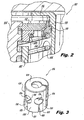
- hold-down sleeve 116 includes a stop structure 118 that engages a corresponding structure on main spring guide 110, as indicated in Fig. 2 . Stop structure 118 prevents main spring 106 from pushing main spring guide 110 beyond a predetermined location with respect to gap 114, regardless of whether main spring 106 is relaxed or partially compressed when valve body 102 is in the closed condition. Thus, a precise predetermined minimum width of gap 114 can be maintained with valve assembly 100 in the closed or no-flow condition.
- hold-down sleeve 116 includes an upstream end portion 120, a downstream end portion 122, and a longitudinally running lateral wall 124 extending therebetween.
- Lateral wall 124 includes six circumferentially spaced apart fuel ports 126 each with an associated elongate slot 128 extending to downstream end portion 122.
- Fuel ports 126 facilitate fluid flow within the bore of inlet section 12 from a space exterior to hold-down sleeve 116 to a space interior thereto.
- fuel ports 126 and slots 128 provide flexibility to six deflectable fingers 130 defined circumferentially between each adjacent pair of slots 128. The flexibility of fingers 130 provides for radial expansion of main opening 132 during construction of valve assembly 100, as will be described in greater detail below.
- Downstream end portion 122 includes a radially inwardly extending cleat 134, a portion of which is defined at the end of each finger 130. Cleat 134 engages valve body 102, as is described below with respect to Figs. 7 and 10-12 .
- Hold-down sleeve 116 can be constructed of high strength, corrosive resistant metallic materials, such as stainless steel, the like, or any other material suitable for a given application.
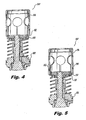
- FIG. 4 illustrates hold-down sleeve 116 with its main opening 132 advanced over main spring guide 110.
- the flexibility of fingers 130 of hold-down sleeve 116 allows main opening 132 to expand radially as needed to advance over the wide portion of main spring guide 110. This flexibility also allows main opening 132 to expand as needed to advance over a wide portion of valve body 102 just prior to cleat 134 engaging circumferential groove 136 defined in the downstream end portion of valve body 102, as shown in Fig. 6 .
- cleat 134 is fully engaged in groove 136 of the downstream end portion of valve body 102 for locking retention of the valve components.
- Cleat 134 and groove 136 prevent movement of hold-down sleeve 116 with respect to the stationary portion of valve body 102. This immobility of hold-down sleeve 116 ensures stop structure 118 will properly engage main spring guide 110 as described above.
- the dimensions and materials used for the various components of the valve assembly may cause fingers 130 of hold-down sleeve 116 to undergo plastic deformation.
- Plastic deformation of fingers 130 can occur, for example, during the radial expansion of main opening 132 while passing over valve body 102, main spring guide 110, and/or other components. Such plastic deformation can leave main opening 132 partially expanded, preventing cleat 134 from fully engaging groove 136 as shown in Fig. 8 .
- Figs. 9-12 show how this incomplete engagement can be overcome.
- injector 10 includes a valve housing 138 within inlet section 12.
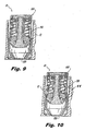
- An initial stage of seating of valve assembly 100 into valve housing 138 is shown in Fig. 9 .
- Distended fingers 130 can be forced into a position to fully engage cleat 134 within groove 136 as valve assembly 100 is advanced into valve housing 138, as shown in Fig. 10 .
- Fig. 11 shows an enlarged view of valve housing 138 and cleat 134.
- the radially outer portion of cleat 134 includes a chamfer 140 and the radially inner edge of valve housing 138 includes a corresponding chamfer 142.
- chamfers 140 and 142 slide along one another pushing cleat 134 into full engagement with groove 136.
- hold-down sleeve 116 and valve housing 138 include chamfers
- any other suitable chamfer configuration can be used to facilitate engagement of a valve housing outboard of a hold-down sleeve without departing from the spirit and scope of the invention.
- white cleat 134 is shown and described as being part of hold down sleeve 116
- groove 136 is shown and described as being defined in valve body 102
- a cleat can be defined in the valve body with a corresponding grove or other suitable recess defined in a hold down sleeve without departing from the spirit and scope of the invention.
- any other suitable type of engagement between a hold down sleeve and valve body can be used without departing from the spirit and scope of the invention.
- Fig. 12 shows injector 10 with valve assembly 100 fully seated in valve housing 138.
- cleat 134 is prevented from radially outward movement, which could otherwise disengage cleat 134 from groove 136, by the engagement of valve housing 138 outboard of fingers 130.
- the engagement of hold-down sleeve 116 with valve body 102 is reinforced by the limit on radial expansion against valve housing 138. This provides a redundant locking mechanism that is difficult to disrupt by outside forces, for example.
- valve assembly 100 is independent of being altered by any welding processes within in injector 10, is not directly connected to nozzle body 20, and is shielded form any negative effects of the welding process.
- valve assembly 100 is shielded by not being in direct contact with the outer casing of injector 10. While welding the outer cap of a conventional injector, for example, extreme heat can transfer from component to component in injectors with direct contact among components.
- valve assembly 100 is not in direct contact with the outer casing of injector 10, there is a physical fluid space between the outside casing of injector 10 and valve assembly 100, insulating valve assembly 100 from the negative effects of welding and engine heating described above. Another advantage of the configurations described above is that valve assembly 100 is self-contained, which allows for easier subassembly into injector 10 or into any other components.
Landscapes
- Engineering & Computer Science (AREA)
- General Engineering & Computer Science (AREA)
- Chemical & Material Sciences (AREA)
- Combustion & Propulsion (AREA)
- Mechanical Engineering (AREA)
- Fuel-Injection Apparatus (AREA)
- Safety Valves (AREA)
Applications Claiming Priority (1)
| Application Number | Priority Date | Filing Date | Title |
|---|---|---|---|
| US12/544,265 US8636263B2 (en) | 2009-08-20 | 2009-08-20 | System and method for locking retention of valve components |
Publications (3)
| Publication Number | Publication Date |
|---|---|
| EP2287504A2 true EP2287504A2 (fr) | 2011-02-23 |
| EP2287504A3 EP2287504A3 (fr) | 2012-02-22 |
| EP2287504B1 EP2287504B1 (fr) | 2013-04-03 |
Family
ID=42830738
Family Applications (1)
| Application Number | Title | Priority Date | Filing Date |
|---|---|---|---|
| EP10251345A Not-in-force EP2287504B1 (fr) | 2009-08-20 | 2010-07-29 | Système et procédé pour bloquer la rétention de composants de valve |
Country Status (2)
| Country | Link |
|---|---|
| US (1) | US8636263B2 (fr) |
| EP (1) | EP2287504B1 (fr) |
Cited By (1)
| Publication number | Priority date | Publication date | Assignee | Title |
|---|---|---|---|---|
| EP3460334A1 (fr) * | 2017-09-25 | 2019-03-27 | Delavan, Inc. | Contrôle électronique de carburant pour moteurs à turbine à gaz |
Families Citing this family (8)
| Publication number | Priority date | Publication date | Assignee | Title |
|---|---|---|---|---|
| FR3011619B1 (fr) * | 2013-10-08 | 2018-03-02 | Safran Aircraft Engines | Injecteur de carburant pour une turbomachine |
| US9581121B2 (en) | 2014-10-24 | 2017-02-28 | Delavan Inc. | Retention feature for fuel injector nozzle |
| US10364751B2 (en) | 2015-08-03 | 2019-07-30 | Delavan Inc | Fuel staging |
| US10487957B2 (en) | 2015-08-13 | 2019-11-26 | Delavan Inc. | Fluid valves |
| FR3051844B1 (fr) * | 2016-05-31 | 2020-03-27 | Safran Aircraft Engines | Chambre entre un embout d'entree et un obturateur, pour injecteur de turbomachine |
| CN107023401A (zh) * | 2017-05-28 | 2017-08-08 | 西安成立航空制造有限公司 | 一种航空发动机燃油喷嘴用预燃级副油路活门及其使用方法 |
| US11466859B2 (en) * | 2020-12-18 | 2022-10-11 | Pratt & Whitney Canada Corp. | Gap filler for a fuel system gallery |
| CN114033559A (zh) * | 2021-10-29 | 2022-02-11 | 中国航发贵州红林航空动力控制科技有限公司 | 一种带自锁功能的调节器 |
Citations (1)
| Publication number | Priority date | Publication date | Assignee | Title |
|---|---|---|---|---|
| US5732730A (en) | 1995-09-11 | 1998-03-31 | Delavan Inc | Combined check valve and metering valve assembly |
Family Cites Families (11)
| Publication number | Priority date | Publication date | Assignee | Title |
|---|---|---|---|---|
| US2586147A (en) * | 1947-08-07 | 1952-02-19 | Caserta Michele | Reaction type valve |
| US2969925A (en) * | 1958-02-03 | 1961-01-31 | Delavan Mfg Company | Multiple variable area orifice injector |
| US3157191A (en) * | 1961-04-21 | 1964-11-17 | Diexell Dev And Mfg Company | Rotating cylinder guided check-valve assembly |
| US3662959A (en) * | 1970-08-07 | 1972-05-16 | Parker Hannifin Corp | Fuel injection nozzle |
| US4570668A (en) | 1984-01-16 | 1986-02-18 | Parker-Hannifin Corporation | Flow dividing valve |
| US4726396A (en) * | 1986-10-22 | 1988-02-23 | Ex-Cell-O Corporation | Fluid valve assembly |
| US5417054A (en) * | 1992-05-19 | 1995-05-23 | Fuel Systems Textron, Inc. | Fuel purging fuel injector |
| US5809771A (en) * | 1996-01-19 | 1998-09-22 | Woodward Governor Company | Aircraft engine fuel system |
| DE19907348A1 (de) * | 1999-02-20 | 2000-08-24 | Bosch Gmbh Robert | Kraftstoffeinspritzventil |
| FR2832457B1 (fr) | 2001-11-20 | 2004-07-23 | Snecma Moteurs | Dispositif doseur de combustible pour injecteur de turbomachine |
| US7506663B2 (en) * | 2006-07-20 | 2009-03-24 | Fleetguard, Inc. | Magnetic check valve |
-
2009
- 2009-08-20 US US12/544,265 patent/US8636263B2/en not_active Expired - Fee Related
-
2010
- 2010-07-29 EP EP10251345A patent/EP2287504B1/fr not_active Not-in-force
Patent Citations (1)
| Publication number | Priority date | Publication date | Assignee | Title |
|---|---|---|---|---|
| US5732730A (en) | 1995-09-11 | 1998-03-31 | Delavan Inc | Combined check valve and metering valve assembly |
Cited By (2)
| Publication number | Priority date | Publication date | Assignee | Title |
|---|---|---|---|---|
| EP3460334A1 (fr) * | 2017-09-25 | 2019-03-27 | Delavan, Inc. | Contrôle électronique de carburant pour moteurs à turbine à gaz |
| US11053862B2 (en) | 2017-09-25 | 2021-07-06 | Delavan Inc. | Electronic fuel control for gas turbine engines |
Also Published As
| Publication number | Publication date |
|---|---|
| US8636263B2 (en) | 2014-01-28 |
| EP2287504A3 (fr) | 2012-02-22 |
| EP2287504B1 (fr) | 2013-04-03 |
| US20110041805A1 (en) | 2011-02-24 |
Similar Documents
| Publication | Publication Date | Title |
|---|---|---|
| EP2287504B1 (fr) | Système et procédé pour bloquer la rétention de composants de valve | |
| US9435218B2 (en) | Systems relating to axial positioning turbine casings and blade tip clearance in gas turbine engines | |
| CA2608287C (fr) | Bride d'injecteur de carburant a transfert de chaleur reduit | |
| CA2904481C (fr) | Dispositif de dosage compact pour injecteur a deux circuits de carburant pour une turbomachine d'aeronef | |
| US9038601B2 (en) | Flow limiter assembly for a fuel system of an internal combustion engine | |
| US9494079B2 (en) | Turbine engine fuel injector with permanent leakage flow | |
| US9488107B2 (en) | Turbine engine fuel injector with leakage flow controlled by position of metering valve | |
| US9453462B2 (en) | Filter bypass valve | |
| US20150096301A1 (en) | Fuel injector for a turbine engine | |
| US20100187451A1 (en) | Pressure regulating valve for aircraft engine | |
| EP2483545B1 (fr) | Buse de carburant à surface variable à logement interne | |
| US11946549B2 (en) | Fuel nozzle with reduced flow tolerance | |
| US9068510B2 (en) | Machined springs for injector applications | |
| US20130283763A1 (en) | Pressure regulating valve | |
| EP2860389B1 (fr) | Ensemble d'injecteur de carburant | |
| US8511330B1 (en) | Servo minimum pressure valve | |
| CN114729590A (zh) | 紧凑型活塞阀 | |
| CN114423928B (zh) | 用于对涡轮机的外壳体进行冷却的装置和设置有这种装置的涡轮机 | |
| CN105142751A (zh) | 球形接触球接头型泄流滑阀 | |
| EP4015909B1 (fr) | Assemblage de buse de carburant avec agent de remplissage | |
| EP3017184B1 (fr) | Système d'injection de carburant | |
| US6722131B1 (en) | Fuel control valve | |
| JP2008008281A (ja) | 燃料噴射弁 | |
| DE102024101441B4 (de) | Gasinjektor für eine Brennkraftmaschine | |
| EP3221642B1 (fr) | Injecteur à lance pour injecter du carburant dans une chambre de combustion d'une turbine à gaz |
Legal Events
| Date | Code | Title | Description |
|---|---|---|---|
| PUAI | Public reference made under article 153(3) epc to a published international application that has entered the european phase |
Free format text: ORIGINAL CODE: 0009012 |
|
| 17P | Request for examination filed |
Effective date: 20100820 |
|
| AK | Designated contracting states |
Kind code of ref document: A2 Designated state(s): AL AT BE BG CH CY CZ DE DK EE ES FI FR GB GR HR HU IE IS IT LI LT LU LV MC MK MT NL NO PL PT RO SE SI SK SM TR |
|
| AX | Request for extension of the european patent |
Extension state: BA ME RS |
|
| REG | Reference to a national code |
Ref country code: DE Ref legal event code: R079 Ref document number: 602010005892 Country of ref document: DE Free format text: PREVIOUS MAIN CLASS: F16K0031122000 Ipc: F16K0017040000 |
|
| PUAL | Search report despatched |
Free format text: ORIGINAL CODE: 0009013 |
|
| AK | Designated contracting states |
Kind code of ref document: A3 Designated state(s): AL AT BE BG CH CY CZ DE DK EE ES FI FR GB GR HR HU IE IS IT LI LT LU LV MC MK MT NL NO PL PT RO SE SI SK SM TR |
|
| AX | Request for extension of the european patent |
Extension state: BA ME RS |
|
| RIC1 | Information provided on ipc code assigned before grant |
Ipc: F02C 9/26 20060101ALI20120113BHEP Ipc: G05D 7/01 20060101ALI20120113BHEP Ipc: F16K 17/06 20060101ALI20120113BHEP Ipc: F16K 17/04 20060101AFI20120113BHEP Ipc: F02C 7/232 20060101ALI20120113BHEP |
|
| GRAP | Despatch of communication of intention to grant a patent |
Free format text: ORIGINAL CODE: EPIDOSNIGR1 |
|
| GRAS | Grant fee paid |
Free format text: ORIGINAL CODE: EPIDOSNIGR3 |
|
| GRAA | (expected) grant |
Free format text: ORIGINAL CODE: 0009210 |
|
| AK | Designated contracting states |
Kind code of ref document: B1 Designated state(s): AL AT BE BG CH CY CZ DE DK EE ES FI FR GB GR HR HU IE IS IT LI LT LU LV MC MK MT NL NO PL PT RO SE SI SK SM TR |
|
| REG | Reference to a national code |
Ref country code: GB Ref legal event code: FG4D |
|
| REG | Reference to a national code |
Ref country code: CH Ref legal event code: EP Ref country code: AT Ref legal event code: REF Ref document number: 604959 Country of ref document: AT Kind code of ref document: T Effective date: 20130415 |
|
| REG | Reference to a national code |
Ref country code: IE Ref legal event code: FG4D |
|
| REG | Reference to a national code |
Ref country code: DE Ref legal event code: R096 Ref document number: 602010005892 Country of ref document: DE Effective date: 20130529 |
|
| REG | Reference to a national code |
Ref country code: AT Ref legal event code: MK05 Ref document number: 604959 Country of ref document: AT Kind code of ref document: T Effective date: 20130403 |
|
| PG25 | Lapsed in a contracting state [announced via postgrant information from national office to epo] |
Ref country code: SI Free format text: LAPSE BECAUSE OF FAILURE TO SUBMIT A TRANSLATION OF THE DESCRIPTION OR TO PAY THE FEE WITHIN THE PRESCRIBED TIME-LIMIT Effective date: 20130403 |
|
| REG | Reference to a national code |
Ref country code: NL Ref legal event code: VDEP Effective date: 20130403 |
|
| REG | Reference to a national code |
Ref country code: LT Ref legal event code: MG4D |
|
| PG25 | Lapsed in a contracting state [announced via postgrant information from national office to epo] |
Ref country code: BE Free format text: LAPSE BECAUSE OF FAILURE TO SUBMIT A TRANSLATION OF THE DESCRIPTION OR TO PAY THE FEE WITHIN THE PRESCRIBED TIME-LIMIT Effective date: 20130403 Ref country code: IS Free format text: LAPSE BECAUSE OF FAILURE TO SUBMIT A TRANSLATION OF THE DESCRIPTION OR TO PAY THE FEE WITHIN THE PRESCRIBED TIME-LIMIT Effective date: 20130803 Ref country code: SE Free format text: LAPSE BECAUSE OF FAILURE TO SUBMIT A TRANSLATION OF THE DESCRIPTION OR TO PAY THE FEE WITHIN THE PRESCRIBED TIME-LIMIT Effective date: 20130403 Ref country code: ES Free format text: LAPSE BECAUSE OF FAILURE TO SUBMIT A TRANSLATION OF THE DESCRIPTION OR TO PAY THE FEE WITHIN THE PRESCRIBED TIME-LIMIT Effective date: 20130714 Ref country code: LT Free format text: LAPSE BECAUSE OF FAILURE TO SUBMIT A TRANSLATION OF THE DESCRIPTION OR TO PAY THE FEE WITHIN THE PRESCRIBED TIME-LIMIT Effective date: 20130403 Ref country code: NO Free format text: LAPSE BECAUSE OF FAILURE TO SUBMIT A TRANSLATION OF THE DESCRIPTION OR TO PAY THE FEE WITHIN THE PRESCRIBED TIME-LIMIT Effective date: 20130703 Ref country code: AT Free format text: LAPSE BECAUSE OF FAILURE TO SUBMIT A TRANSLATION OF THE DESCRIPTION OR TO PAY THE FEE WITHIN THE PRESCRIBED TIME-LIMIT Effective date: 20130403 Ref country code: PT Free format text: LAPSE BECAUSE OF FAILURE TO SUBMIT A TRANSLATION OF THE DESCRIPTION OR TO PAY THE FEE WITHIN THE PRESCRIBED TIME-LIMIT Effective date: 20130805 Ref country code: GR Free format text: LAPSE BECAUSE OF FAILURE TO SUBMIT A TRANSLATION OF THE DESCRIPTION OR TO PAY THE FEE WITHIN THE PRESCRIBED TIME-LIMIT Effective date: 20130704 Ref country code: NL Free format text: LAPSE BECAUSE OF FAILURE TO SUBMIT A TRANSLATION OF THE DESCRIPTION OR TO PAY THE FEE WITHIN THE PRESCRIBED TIME-LIMIT Effective date: 20130403 Ref country code: FI Free format text: LAPSE BECAUSE OF FAILURE TO SUBMIT A TRANSLATION OF THE DESCRIPTION OR TO PAY THE FEE WITHIN THE PRESCRIBED TIME-LIMIT Effective date: 20130403 |
|
| PGFP | Annual fee paid to national office [announced via postgrant information from national office to epo] |
Ref country code: DE Payment date: 20130724 Year of fee payment: 4 |
|
| PG25 | Lapsed in a contracting state [announced via postgrant information from national office to epo] |
Ref country code: LV Free format text: LAPSE BECAUSE OF FAILURE TO SUBMIT A TRANSLATION OF THE DESCRIPTION OR TO PAY THE FEE WITHIN THE PRESCRIBED TIME-LIMIT Effective date: 20130403 Ref country code: CY Free format text: LAPSE BECAUSE OF FAILURE TO SUBMIT A TRANSLATION OF THE DESCRIPTION OR TO PAY THE FEE WITHIN THE PRESCRIBED TIME-LIMIT Effective date: 20130403 Ref country code: HR Free format text: LAPSE BECAUSE OF FAILURE TO SUBMIT A TRANSLATION OF THE DESCRIPTION OR TO PAY THE FEE WITHIN THE PRESCRIBED TIME-LIMIT Effective date: 20130403 Ref country code: PL Free format text: LAPSE BECAUSE OF FAILURE TO SUBMIT A TRANSLATION OF THE DESCRIPTION OR TO PAY THE FEE WITHIN THE PRESCRIBED TIME-LIMIT Effective date: 20130403 Ref country code: BG Free format text: LAPSE BECAUSE OF FAILURE TO SUBMIT A TRANSLATION OF THE DESCRIPTION OR TO PAY THE FEE WITHIN THE PRESCRIBED TIME-LIMIT Effective date: 20130703 |
|
| PGFP | Annual fee paid to national office [announced via postgrant information from national office to epo] |
Ref country code: FR Payment date: 20130724 Year of fee payment: 4 |
|
| PG25 | Lapsed in a contracting state [announced via postgrant information from national office to epo] |
Ref country code: CZ Free format text: LAPSE BECAUSE OF FAILURE TO SUBMIT A TRANSLATION OF THE DESCRIPTION OR TO PAY THE FEE WITHIN THE PRESCRIBED TIME-LIMIT Effective date: 20130403 Ref country code: SK Free format text: LAPSE BECAUSE OF FAILURE TO SUBMIT A TRANSLATION OF THE DESCRIPTION OR TO PAY THE FEE WITHIN THE PRESCRIBED TIME-LIMIT Effective date: 20130403 Ref country code: EE Free format text: LAPSE BECAUSE OF FAILURE TO SUBMIT A TRANSLATION OF THE DESCRIPTION OR TO PAY THE FEE WITHIN THE PRESCRIBED TIME-LIMIT Effective date: 20130403 Ref country code: DK Free format text: LAPSE BECAUSE OF FAILURE TO SUBMIT A TRANSLATION OF THE DESCRIPTION OR TO PAY THE FEE WITHIN THE PRESCRIBED TIME-LIMIT Effective date: 20130403 |
|
| PLBE | No opposition filed within time limit |
Free format text: ORIGINAL CODE: 0009261 |
|
| STAA | Information on the status of an ep patent application or granted ep patent |
Free format text: STATUS: NO OPPOSITION FILED WITHIN TIME LIMIT |
|
| PG25 | Lapsed in a contracting state [announced via postgrant information from national office to epo] |
Ref country code: MC Free format text: LAPSE BECAUSE OF FAILURE TO SUBMIT A TRANSLATION OF THE DESCRIPTION OR TO PAY THE FEE WITHIN THE PRESCRIBED TIME-LIMIT Effective date: 20130403 Ref country code: IT Free format text: LAPSE BECAUSE OF FAILURE TO SUBMIT A TRANSLATION OF THE DESCRIPTION OR TO PAY THE FEE WITHIN THE PRESCRIBED TIME-LIMIT Effective date: 20130403 Ref country code: RO Free format text: LAPSE BECAUSE OF FAILURE TO SUBMIT A TRANSLATION OF THE DESCRIPTION OR TO PAY THE FEE WITHIN THE PRESCRIBED TIME-LIMIT Effective date: 20130403 |
|
| 26N | No opposition filed |
Effective date: 20140106 |
|
| REG | Reference to a national code |
Ref country code: DE Ref legal event code: R097 Ref document number: 602010005892 Country of ref document: DE Effective date: 20140106 |
|
| REG | Reference to a national code |
Ref country code: IE Ref legal event code: MM4A |
|
| PG25 | Lapsed in a contracting state [announced via postgrant information from national office to epo] |
Ref country code: IE Free format text: LAPSE BECAUSE OF NON-PAYMENT OF DUE FEES Effective date: 20130729 |
|
| REG | Reference to a national code |
Ref country code: DE Ref legal event code: R119 Ref document number: 602010005892 Country of ref document: DE |
|
| REG | Reference to a national code |
Ref country code: CH Ref legal event code: PL |
|
| REG | Reference to a national code |
Ref country code: FR Ref legal event code: ST Effective date: 20150331 |
|
| PG25 | Lapsed in a contracting state [announced via postgrant information from national office to epo] |
Ref country code: LI Free format text: LAPSE BECAUSE OF NON-PAYMENT OF DUE FEES Effective date: 20140731 Ref country code: CH Free format text: LAPSE BECAUSE OF NON-PAYMENT OF DUE FEES Effective date: 20140731 Ref country code: DE Free format text: LAPSE BECAUSE OF NON-PAYMENT OF DUE FEES Effective date: 20150203 |
|
| REG | Reference to a national code |
Ref country code: DE Ref legal event code: R119 Ref document number: 602010005892 Country of ref document: DE Effective date: 20150203 |
|
| PG25 | Lapsed in a contracting state [announced via postgrant information from national office to epo] |
Ref country code: SM Free format text: LAPSE BECAUSE OF FAILURE TO SUBMIT A TRANSLATION OF THE DESCRIPTION OR TO PAY THE FEE WITHIN THE PRESCRIBED TIME-LIMIT Effective date: 20130403 Ref country code: FR Free format text: LAPSE BECAUSE OF NON-PAYMENT OF DUE FEES Effective date: 20140731 |
|
| PG25 | Lapsed in a contracting state [announced via postgrant information from national office to epo] |
Ref country code: MT Free format text: LAPSE BECAUSE OF FAILURE TO SUBMIT A TRANSLATION OF THE DESCRIPTION OR TO PAY THE FEE WITHIN THE PRESCRIBED TIME-LIMIT Effective date: 20130403 Ref country code: TR Free format text: LAPSE BECAUSE OF FAILURE TO SUBMIT A TRANSLATION OF THE DESCRIPTION OR TO PAY THE FEE WITHIN THE PRESCRIBED TIME-LIMIT Effective date: 20130403 |
|
| PG25 | Lapsed in a contracting state [announced via postgrant information from national office to epo] |
Ref country code: HU Free format text: LAPSE BECAUSE OF FAILURE TO SUBMIT A TRANSLATION OF THE DESCRIPTION OR TO PAY THE FEE WITHIN THE PRESCRIBED TIME-LIMIT; INVALID AB INITIO Effective date: 20100729 Ref country code: MK Free format text: LAPSE BECAUSE OF FAILURE TO SUBMIT A TRANSLATION OF THE DESCRIPTION OR TO PAY THE FEE WITHIN THE PRESCRIBED TIME-LIMIT Effective date: 20130403 Ref country code: LU Free format text: LAPSE BECAUSE OF NON-PAYMENT OF DUE FEES Effective date: 20130729 |
|
| PG25 | Lapsed in a contracting state [announced via postgrant information from national office to epo] |
Ref country code: AL Free format text: LAPSE BECAUSE OF FAILURE TO SUBMIT A TRANSLATION OF THE DESCRIPTION OR TO PAY THE FEE WITHIN THE PRESCRIBED TIME-LIMIT Effective date: 20130403 |
|
| PGFP | Annual fee paid to national office [announced via postgrant information from national office to epo] |
Ref country code: GB Payment date: 20240620 Year of fee payment: 15 |
|
| GBPC | Gb: european patent ceased through non-payment of renewal fee |
Effective date: 20250729 |
|
| PG25 | Lapsed in a contracting state [announced via postgrant information from national office to epo] |
Ref country code: GB Free format text: LAPSE BECAUSE OF NON-PAYMENT OF DUE FEES Effective date: 20250729 |