EP2287509A1 - Kupplung für einen verstärkten großen Bohrlochschlauch - Google Patents
Kupplung für einen verstärkten großen Bohrlochschlauch Download PDFInfo
- Publication number
- EP2287509A1 EP2287509A1 EP10172986A EP10172986A EP2287509A1 EP 2287509 A1 EP2287509 A1 EP 2287509A1 EP 10172986 A EP10172986 A EP 10172986A EP 10172986 A EP10172986 A EP 10172986A EP 2287509 A1 EP2287509 A1 EP 2287509A1
- Authority
- EP
- European Patent Office
- Prior art keywords
- hose
- carcass
- coupling
- tubular body
- anchor
- Prior art date
- Legal status (The legal status is an assumption and is not a legal conclusion. Google has not performed a legal analysis and makes no representation as to the accuracy of the status listed.)
- Withdrawn
Links
- 230000008878 coupling Effects 0.000 title claims abstract description 93
- 238000010168 coupling process Methods 0.000 title claims abstract description 93
- 238000005859 coupling reaction Methods 0.000 title claims abstract description 93
- 239000011324 bead Substances 0.000 claims abstract description 36
- 230000014759 maintenance of location Effects 0.000 claims abstract description 34
- 239000004744 fabric Substances 0.000 claims description 23
- 230000002787 reinforcement Effects 0.000 claims description 13
- 230000003014 reinforcing effect Effects 0.000 claims description 7
- 239000011800 void material Substances 0.000 claims description 2
- 238000004873 anchoring Methods 0.000 description 26
- 238000007667 floating Methods 0.000 description 21
- 229910000831 Steel Inorganic materials 0.000 description 13
- 239000010959 steel Substances 0.000 description 13
- XLYOFNOQVPJJNP-UHFFFAOYSA-N water Substances O XLYOFNOQVPJJNP-UHFFFAOYSA-N 0.000 description 8
- 229920001971 elastomer Polymers 0.000 description 7
- 239000005060 rubber Substances 0.000 description 7
- 239000006260 foam Substances 0.000 description 5
- 239000010779 crude oil Substances 0.000 description 4
- 239000013535 sea water Substances 0.000 description 4
- 229920000459 Nitrile rubber Polymers 0.000 description 3
- 238000004519 manufacturing process Methods 0.000 description 3
- 239000003921 oil Substances 0.000 description 3
- 229920002943 EPDM rubber Polymers 0.000 description 2
- 238000005452 bending Methods 0.000 description 2
- 230000008901 benefit Effects 0.000 description 2
- 239000004568 cement Substances 0.000 description 2
- 229920001973 fluoroelastomer Polymers 0.000 description 2
- 239000002184 metal Substances 0.000 description 2
- 239000003208 petroleum Substances 0.000 description 2
- 238000003860 storage Methods 0.000 description 2
- 239000000126 substance Substances 0.000 description 2
- 230000000153 supplemental effect Effects 0.000 description 2
- 239000004753 textile Substances 0.000 description 2
- ROGIWVXWXZRRMZ-UHFFFAOYSA-N 2-methylbuta-1,3-diene;styrene Chemical compound CC(=C)C=C.C=CC1=CC=CC=C1 ROGIWVXWXZRRMZ-UHFFFAOYSA-N 0.000 description 1
- 229920002449 FKM Polymers 0.000 description 1
- 244000043261 Hevea brasiliensis Species 0.000 description 1
- 229920000271 Kevlar® Polymers 0.000 description 1
- 239000004677 Nylon Substances 0.000 description 1
- 239000004698 Polyethylene Substances 0.000 description 1
- 229920005830 Polyurethane Foam Polymers 0.000 description 1
- 229920005683 SIBR Polymers 0.000 description 1
- 230000009471 action Effects 0.000 description 1
- 230000002411 adverse Effects 0.000 description 1
- 229920006231 aramid fiber Polymers 0.000 description 1
- 230000009286 beneficial effect Effects 0.000 description 1
- 229920003020 cross-linked polyethylene Polymers 0.000 description 1
- 239000004703 cross-linked polyethylene Substances 0.000 description 1
- 230000007613 environmental effect Effects 0.000 description 1
- 239000012530 fluid Substances 0.000 description 1
- 238000002955 isolation Methods 0.000 description 1
- 229920003049 isoprene rubber Polymers 0.000 description 1
- 239000007788 liquid Substances 0.000 description 1
- 230000007246 mechanism Effects 0.000 description 1
- 239000000203 mixture Substances 0.000 description 1
- 238000012986 modification Methods 0.000 description 1
- 230000004048 modification Effects 0.000 description 1
- 229920003052 natural elastomer Polymers 0.000 description 1
- 229920001194 natural rubber Polymers 0.000 description 1
- 229920001778 nylon Polymers 0.000 description 1
- 230000002085 persistent effect Effects 0.000 description 1
- 229920002857 polybutadiene Polymers 0.000 description 1
- 229920000728 polyester Polymers 0.000 description 1
- -1 polyethylene Polymers 0.000 description 1
- 229920000573 polyethylene Polymers 0.000 description 1
- 239000011527 polyurethane coating Substances 0.000 description 1
- 239000011496 polyurethane foam Substances 0.000 description 1
- 238000000926 separation method Methods 0.000 description 1
- 229920003048 styrene butadiene rubber Polymers 0.000 description 1
- 229920003051 synthetic elastomer Polymers 0.000 description 1
- 229920001169 thermoplastic Polymers 0.000 description 1
- 239000004416 thermosoftening plastic Substances 0.000 description 1
- 238000003466 welding Methods 0.000 description 1
Images


Classifications
-
- F—MECHANICAL ENGINEERING; LIGHTING; HEATING; WEAPONS; BLASTING
- F16—ENGINEERING ELEMENTS AND UNITS; GENERAL MEASURES FOR PRODUCING AND MAINTAINING EFFECTIVE FUNCTIONING OF MACHINES OR INSTALLATIONS; THERMAL INSULATION IN GENERAL
- F16L—PIPES; JOINTS OR FITTINGS FOR PIPES; SUPPORTS FOR PIPES, CABLES OR PROTECTIVE TUBING; MEANS FOR THERMAL INSULATION IN GENERAL
- F16L33/00—Arrangements for connecting hoses to rigid members; Rigid hose-connectors, i.e. single members engaging both hoses
- F16L33/30—Arrangements for connecting hoses to rigid members; Rigid hose-connectors, i.e. single members engaging both hoses comprising parts inside the hoses only
-
- B—PERFORMING OPERATIONS; TRANSPORTING
- B63—SHIPS OR OTHER WATERBORNE VESSELS; RELATED EQUIPMENT
- B63B—SHIPS OR OTHER WATERBORNE VESSELS; EQUIPMENT FOR SHIPPING
- B63B27/00—Arrangement of ship-based loading or unloading equipment for cargo or passengers
- B63B27/30—Arrangement of ship-based loading or unloading equipment for transfer at sea between ships or between ships and off-shore structures
- B63B27/34—Arrangement of ship-based loading or unloading equipment for transfer at sea between ships or between ships and off-shore structures using pipe-lines
-
- F—MECHANICAL ENGINEERING; LIGHTING; HEATING; WEAPONS; BLASTING
- F16—ENGINEERING ELEMENTS AND UNITS; GENERAL MEASURES FOR PRODUCING AND MAINTAINING EFFECTIVE FUNCTIONING OF MACHINES OR INSTALLATIONS; THERMAL INSULATION IN GENERAL
- F16L—PIPES; JOINTS OR FITTINGS FOR PIPES; SUPPORTS FOR PIPES, CABLES OR PROTECTIVE TUBING; MEANS FOR THERMAL INSULATION IN GENERAL
- F16L11/00—Hoses, i.e. flexible pipes
- F16L11/04—Hoses, i.e. flexible pipes made of rubber or flexible plastics
- F16L11/12—Hoses, i.e. flexible pipes made of rubber or flexible plastics with arrangements for particular purposes, e.g. specially profiled, with protecting layer, heated, electrically conducting
- F16L11/133—Hoses, i.e. flexible pipes made of rubber or flexible plastics with arrangements for particular purposes, e.g. specially profiled, with protecting layer, heated, electrically conducting buoyant
-
- F—MECHANICAL ENGINEERING; LIGHTING; HEATING; WEAPONS; BLASTING
- F16—ENGINEERING ELEMENTS AND UNITS; GENERAL MEASURES FOR PRODUCING AND MAINTAINING EFFECTIVE FUNCTIONING OF MACHINES OR INSTALLATIONS; THERMAL INSULATION IN GENERAL
- F16L—PIPES; JOINTS OR FITTINGS FOR PIPES; SUPPORTS FOR PIPES, CABLES OR PROTECTIVE TUBING; MEANS FOR THERMAL INSULATION IN GENERAL
- F16L33/00—Arrangements for connecting hoses to rigid members; Rigid hose-connectors, i.e. single members engaging both hoses
- F16L33/01—Arrangements for connecting hoses to rigid members; Rigid hose-connectors, i.e. single members engaging both hoses specially adapted for hoses having a multi-layer wall
-
- F—MECHANICAL ENGINEERING; LIGHTING; HEATING; WEAPONS; BLASTING
- F16—ENGINEERING ELEMENTS AND UNITS; GENERAL MEASURES FOR PRODUCING AND MAINTAINING EFFECTIVE FUNCTIONING OF MACHINES OR INSTALLATIONS; THERMAL INSULATION IN GENERAL
- F16L—PIPES; JOINTS OR FITTINGS FOR PIPES; SUPPORTS FOR PIPES, CABLES OR PROTECTIVE TUBING; MEANS FOR THERMAL INSULATION IN GENERAL
- F16L35/00—Special arrangements used in connection with end fittings of hoses, e.g. safety or protecting devices
-
- B—PERFORMING OPERATIONS; TRANSPORTING
- B63—SHIPS OR OTHER WATERBORNE VESSELS; RELATED EQUIPMENT
- B63B—SHIPS OR OTHER WATERBORNE VESSELS; EQUIPMENT FOR SHIPPING
- B63B27/00—Arrangement of ship-based loading or unloading equipment for cargo or passengers
- B63B27/24—Arrangement of ship-based loading or unloading equipment for cargo or passengers of pipe-lines
Definitions
- the present invention relates to a coupling according to the preamble of claim 1 and to a hose assembly according to the preamble of claim 10.
- a coupling and such a hose assembly are per se known.
- hose can be utilized in a wide array of applications.
- One important application for large bore reinforced hose that is of growing importance in the world today is in loading and unloading oil tankers and floating production storage and offloading units (FPSOs).
- FPSOs floating production storage and offloading units
- Such hose has an inside diameter of 5 cm or greater and typically has an inside diameter ranging from 20 cm to 80 cm.
- Such hose for offshore applications is also typically designed to include a floatation medium to provide the hose with sufficient buoyancy so that it will float on the surface of water.
- Hose for offshore applications typically has reserve buoyancy when filled with sea water which is within the range of 10% to 40%. A reserve buoyancy of at least 20% is frequently demanded by customers. Because vast reserves of petroleum are located under water in many locations around the world including under the North Sea, the Gulf of Mexico, off the coast of Brazil, and off the coast of California there is a growing demand for large bore reinforced floating hose.
- Floating hoses typically run from the bow and/or the stem of FPSOs to shuttle tankers.
- Modem shuttle tankers may have a bow manifold for charging crude oil, but many conventional shuttle tankers have a charging device consisting of a midship manifold for intake of the oil load. For this reason a relatively long loading hose is needed, from the FPSO-vessel to the midship manifold on the shuttle tanker.
- the separation between the vessels, between the stem of the FPSO and the bow of the shuttle tanker is generally about 50 to 200 meters, and the extension of the floating hose is normally between about 150 and 300 meters.
- the floating hoses When the floating hoses are not being used to transfer petroleum they can be allowed to remain floating on the water after being released from the tankers. However, in such cases where the floating hose is left on the water the floating hose may be damaged by being struck by ships, sea creatures or by the movement from waves in stormy weather. In any case, hose wear occurs due to continual wave action. This can lead to a loss of the buoyancy and/or primary carcass failure and over time the hose can begin sink.
- the floating hose can be hoisted onto the FPSO for storage until it is again needed for offloading crude oil to a shuttle tanker.
- This can be done by using a wench to pull the floating hose onto a reel.
- This protects the hose from exposure to waves and the inherent wear associated therewith. It also eliminates the danger of the floating hose being struck by a ship as it is floating at sea.
- pulling the hose onto a reel puts the couplings that connect different sections of hose under a tremendous amount of stress. At the point where the coupling is being pulled onto the reel it experiences a particularly high level of stress and compressive forces. Over time, these forces can cause the hose to fail at or near the point where it is attached to a coupling. In any case, large bore reinforced hoses are prone to failure at their couplings. This is also the case where large tensile loads are encountered in catenary and deep water submarine applications.
- the objective underlying to the present invention is to provide couplings that fulfill the above identified need.
- a further objective is to provide a hose assembly including reinforced hoses that match the above identified needs.
- the hose couplings of this invention can be used to connect sections of large bore reinforced hose to make them more resistant to damage and to provide longer service life.
- These couplings can be used in conjunction with virtually any reinforced hose and are particularly beneficial when used in conjunction with hose that has a propensity to being damaged by virtue of being subjected to axial and bending forces, such as those encountered while being spooled on a reel. More specifically, hose utilizing the couplings of this invention is not as susceptible to being damaged or destroyed by the forces normally encountered during normal usage. This extends the service life of hoses of this invention which include such couplings.
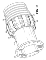
- the present invention more specifically discloses a coupling for a large bore hose, said coupling comprising a tubular body which is adapted for fitting into the end of said large bore hose, said tubular body having a tail end which is adapted to lie inwardly from the end of the hose, said tubular body having an outer end which is adapted to extend beyond an axial end of the hose, and at least one hose carcass anchor which is affixed to the tubular body, wherein the carcass anchor is adapted for the hose carcass and/or load bearing extensions of the carcass to extend through and/or around the carcass anchor.
- the subject invention also reveals a coupling for a large bore hose, said coupling comprising a tubular body which is adapted for fitting into the end of said large bore hose, said tubular body having a tail end which is adapted to lie inwardly from the end of the hose, said tubular body having an outer end which is adapted to extend beyond an axial end of the hose, the outer surface of said tubular body being provided with a plurality of axially spaced retention beads, and at least one hose carcass anchor which is affixed to the tubular body at a point on or outward from the last retention bead toward the outer end of the tubular body, wherein the carcass anchor is adapted for the hose carcass and/or load bearing extensions of the carcass to extend through and around the carcass anchor.
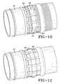
- the subject invention also reveals a hose assembly comprising a reinforced hose having at least one reinforcement layer and a coupling on at least one end of the hose, said coupling comprising a tubular body which is adapted for fitting into the end of said large bore hose, said tubular body having a tail end which is adapted to lie inwardly from the end of the hose, said tubular body having an outer end which is adapted to extend beyond an axial end of the hose, and at least one hose carcass anchor which is affixed to the tubular body, wherein the hose carcass and/or load bearing extensions of the hose carcass extend through and/or around the carcass anchor.
- the subject invention further reveals a hose assembly, sometimes referred to as the "hitching post assembly,” comprising a reinforced hose having at least one reinforcement layer and a coupling on at least one end of the hose, said coupling comprising a tubular body which is adapted for fitting into the end of said large bore hose, said tubular body having a tail end which is adapted to lie inwardly from the end of the hose, said tubular body having an outer end which is adapted to extend beyond an axial end of the hose, the outer surface of said tubular body being provided with a plurality of axially spaced retention beads, and at least one hose carcass anchor which is affixed to the tubular body at a point on or outward from the last retention bead toward the outer end of the tubular body, wherein the hose carcass and/or load bearing extensions of the hose carcass extend through and around the carcass anchor.
- the hitching post assembly comprising a reinforced hose having at least one reinforcement layer and a coupling on at least one
- the couplings of this invention can be beneficially used in conjunctions with hoses of different sizes and that are designed for a wide variety of purposes.
- the couplings of this invention are of particular benefit for use in conjunction with large bore hoses having an inside diameter of at least 5 cm and which typically has an inside diameter ranging from 20 cm to 80 cm and an outside diameter which is within the range of about 40 cm to about 150 cm, such as floating hose that is used in transferring crude oil and other liquids over water (in filling and unloading tanker ships), catenary systems and deep water submarine applications.
- the couplings of this invention can be used in conjunction with floating hose having a carcass with an inside and an outside, a floatation medium surrounding the hose carcass and an outer cover. They may also be used in a single carcass hose that is either designed for floating, submarine applications or as a catenary system.
- This type of floating hose typically has an inside diameter which is within the range of about 30 cm to 80 cm and an outside diameter which is within the range of about 40 cm to about 150 cm. For instance, many commercial floating hoses of this type have an inside diameter of 50 cm (20 inches) and an outside diameter of 95 cm (38 inches).
- the carcass is of a tubular shape and is typically comprised of a base submarine hose complete with end fittings.
- the hose carcass is surrounded by a floatation medium which is typically comprised of several layers of closed cell foam.
- the closed cell foam can be multiple layers of a polymeric foam, such as polyurethane foam or polyethylene foam.
- the floatation medium will have a density and a total volume that is sufficient to provide the floating hose 1 with a reserve buoyancy when filled with sea water which is within the range of 10% to 40%.
- the floating hose will more typically have a reserve buoyancy when filled with sea water which is within the range of 15% to 35%. In most cases the floating hose will have a reserve buoyancy when filled with sea water of about 25%. In fact, many specifications call for a reserve buoyancy of at least 20%.
- the floating hose includes a carcass and can optionally include a second carcass to attain a higher level of safety, performance, and better durability.
- the hose carcass is typically comprised of a cured rubber which can be reinforced with a polymeric fabric, such as nylon or polyester, and/or steel reinforcements.
- the hose carcass can be reinforced with Kevlar® aramid fiber.
- the hose carcass will typically be comprised of a cured rubber, such as natural rubber, synthetic polyisoprene rubber, styrene-butadiene rubber (SBR), polyneoprene rubber, styrene-isoprene rubber, polybutadiene rubber, styrene-isoprene-butadiene rubber, nitrile rubber, carboxylated nitrile rubber, ethylene-propylene-diene monomer rubber (EPDM), or a mixture thereof.
- SBR styrene-butadiene rubber
- the hose carcass will also typically include one or more liners.
- liners will generally be comprised of a nitrile rubber.
- To attain excellent heat resistance, oil resistance, and chemical resistance fluoroelastomers, such as Viton® fluoroelastomer can be used in making the liners as well as thermoplastic liners, such as crosslinked polyethylene.
- the floatation medium can be provided by wrapping multiple layers of closed cell foam around the hose carcass. A thin layer of rubber is preferably laid between the carcass and the floatation medium.
- the floatation medium will normally be about 6 cm to about 18 cm thick. In other words, the floatation medium will extend outwardly from the carcass about 6 cm to about 18 cm.
- the floatation medium will preferably be about 10 cm to about 15 cm thick and will most preferably be about 12 cm to about 14 cm thick.
- the floatation medium is surrounded outwardly with the outer cover of the hose.
- the outer cover is normally comprised of textile breakers with a rubber cover (a textile reinforced rubber cover).
- the outer cover can optionally include a polyurethane coating. In any case, the outer cover is designed to contain and protect the floatation medium from water damage and environmental conditions.
- the key to this invention is providing the coupling with anchors that allow the hose carcass or a load bearing extension of the carcass to extend through and around the anchors. This allows for the stress associated with tensile loading to be delivered directly to the coupling through the carcass anchors rather than through the interface between the hose and the tubular body of the coupling as is the case with the coupling designs of the prior art.
- the carcass anchors will normally extend into the hose no further than the cement line behind the first retention bead. In many cases, the carcass anchors will not extend into the hose as far as the first retention bead.
- the carcass anchor is a plurality of pins that extend radially from the tubular body.
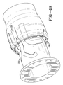
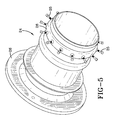
- the carcass anchor is a ring which is affixed to the tubular body through a plurality of rods or plates that extend outwardly from the tubular body to the ring.
- the outer surface of the tubular body is provided with at least one retention bead.
- the outer surface of the tubular body can include two retention beads or a plurality of axially spaced retention beads.
- the carcass anchor is attached to the tubular body at a point on or outward from the retention bead toward the outer end of the tubular body.
- the reinforcing fabric of the hose carcass can extends through and/or around the carcass anchor.
- the carcass anchor is a plurality of pins that extend radially from the tubular body.
- the carcass anchor is a ring which is affixed to the tubular body through a plurality of rods or plates that extend outwardly from the tubular body to the ring.
- the hose will be void of longitudinal supports.
- the carcass wire can be a metal wire or cable, such as a steel wire or cable, which is directly attached to the coupling.
- the outer surface of the tubular body is typically provided with at least one retention bead and can include two retention beads. In some cases, it may be desirable for the outer surface of the tubular body of the coupling to include a plurality of axially spaced retention beads.
- the carcass anchors are normally situated outwardly toward the end of the hose from the first retention bead. For instance, the carcass anchors are situated outwardly toward the end of the hose from the cement line behind the first retention bead. Normally, the carcass anchor is attached to the tubular body at a point on or outward from the last retention bead toward the outer end of the tubular body.
- the carcass anchor is initiated between the outer end of the coupling and the last retention bead on the coupling.
- the last retention bead my be a second retention or a first retention bead.
- a carcass wire is directly attached to the coupling.
Landscapes
- Engineering & Computer Science (AREA)
- General Engineering & Computer Science (AREA)
- Mechanical Engineering (AREA)
- Chemical & Material Sciences (AREA)
- Combustion & Propulsion (AREA)
- Ocean & Marine Engineering (AREA)
- Rigid Pipes And Flexible Pipes (AREA)
Applications Claiming Priority (1)
| Application Number | Priority Date | Filing Date | Title |
|---|---|---|---|
| US23546009P | 2009-08-20 | 2009-08-20 |
Publications (1)
| Publication Number | Publication Date |
|---|---|
| EP2287509A1 true EP2287509A1 (de) | 2011-02-23 |
Family
ID=43127390
Family Applications (1)
| Application Number | Title | Priority Date | Filing Date |
|---|---|---|---|
| EP10172986A Withdrawn EP2287509A1 (de) | 2009-08-20 | 2010-08-17 | Kupplung für einen verstärkten großen Bohrlochschlauch |
Country Status (5)
| Country | Link |
|---|---|
| US (1) | US20110042940A1 (de) |
| EP (1) | EP2287509A1 (de) |
| JP (1) | JP2011043235A (de) |
| CN (1) | CN101994888A (de) |
| BR (1) | BRPI1003068A2 (de) |
Families Citing this family (3)
| Publication number | Priority date | Publication date | Assignee | Title |
|---|---|---|---|---|
| US7992903B1 (en) * | 2008-12-30 | 2011-08-09 | Desimone Frank J | Flex-duct end connector |
| US10295107B2 (en) * | 2016-06-24 | 2019-05-21 | The Boeing Company | Systems and methods for duct protection |
| US10247337B2 (en) | 2017-03-20 | 2019-04-02 | Contitech Usa, Inc. | Hose end construction and fitting |
Citations (3)
| Publication number | Priority date | Publication date | Assignee | Title |
|---|---|---|---|---|
| GB1252804A (de) * | 1968-09-11 | 1971-11-10 | ||
| US4477108A (en) * | 1982-05-17 | 1984-10-16 | Goodall Rubber Company | Flexible hose having an end connection fitting |
| GB2258507A (en) * | 1991-07-24 | 1993-02-10 | Dunlop Ltd | Hose end fitting |
Family Cites Families (1)
| Publication number | Priority date | Publication date | Assignee | Title |
|---|---|---|---|---|
| US7080858B2 (en) * | 2003-11-06 | 2006-07-25 | The Goodyear Tire & Rubber Company | Seawater suction hose and method |
-
2010
- 2010-08-11 US US12/854,257 patent/US20110042940A1/en not_active Abandoned
- 2010-08-13 BR BRPI1003068-9A patent/BRPI1003068A2/pt not_active Application Discontinuation
- 2010-08-17 EP EP10172986A patent/EP2287509A1/de not_active Withdrawn
- 2010-08-19 JP JP2010184095A patent/JP2011043235A/ja not_active Withdrawn
- 2010-08-19 CN CN2010102607256A patent/CN101994888A/zh active Pending
Patent Citations (3)
| Publication number | Priority date | Publication date | Assignee | Title |
|---|---|---|---|---|
| GB1252804A (de) * | 1968-09-11 | 1971-11-10 | ||
| US4477108A (en) * | 1982-05-17 | 1984-10-16 | Goodall Rubber Company | Flexible hose having an end connection fitting |
| GB2258507A (en) * | 1991-07-24 | 1993-02-10 | Dunlop Ltd | Hose end fitting |
Also Published As
| Publication number | Publication date |
|---|---|
| CN101994888A (zh) | 2011-03-30 |
| BRPI1003068A2 (pt) | 2012-04-24 |
| JP2011043235A (ja) | 2011-03-03 |
| US20110042940A1 (en) | 2011-02-24 |
Similar Documents
| Publication | Publication Date | Title |
|---|---|---|
| US10247337B2 (en) | Hose end construction and fitting | |
| US4153079A (en) | Flexible hose lines | |
| US4850395A (en) | High pressure flexible pipe | |
| US9458950B2 (en) | Lining of pipelines to offshore installations | |
| EP2161485A2 (de) | Druckbeständiger schwimmender Schlauch für Aufwickelanwendungen | |
| AU672655B2 (en) | Improvements in and relating to floatable flexible hose | |
| EA014463B1 (ru) | Усовершенствованный шланг | |
| EP2524162B1 (de) | Verbesserungen im zusammenhang mit der ausserbetriebnahme und wiederherstellung von rohrleitungen | |
| HU215806B (hu) | Flexibilis tömlő | |
| CN102245853B (zh) | 软管 | |
| EP2287509A1 (de) | Kupplung für einen verstärkten großen Bohrlochschlauch | |
| JP2021527767A (ja) | 水中係留索 | |
| GB1585914A (en) | Hose | |
| USRE32508E (en) | Hose structure | |
| CN102072367A (zh) | 漂浮式输油软管 | |
| CN201982820U (zh) | 漂浮式输油软管 | |
| JP2001278400A (ja) | 船舶用荷役ホースおよび荷役方法 | |
| US4506622A (en) | Hawser line flotation | |
| JP2000085684A (ja) | 原油等の海中輸送装置 | |
| JP5740933B2 (ja) | フローティングタイプのマリンホースの修理部材及び修理方法 | |
| CN116462152A (zh) | 一种新型的单点系泊水下柔性储液系统 | |
| CN112879662A (zh) | 一种适用于海底管道登陆拖拉浮筒的制作工艺及安装方法 | |
| JP4008637B2 (ja) | サブマリンホース | |
| JP2007146892A (ja) | マリンホース | |
| EP3464974A1 (de) | Abladungsleitung und verfahren zur installation einer abladungsleitung |
Legal Events
| Date | Code | Title | Description |
|---|---|---|---|
| PUAI | Public reference made under article 153(3) epc to a published international application that has entered the european phase |
Free format text: ORIGINAL CODE: 0009012 |
|
| AK | Designated contracting states |
Kind code of ref document: A1 Designated state(s): AL AT BE BG CH CY CZ DE DK EE ES FI FR GB GR HR HU IE IS IT LI LT LU LV MC MK MT NL NO PL PT RO SE SI SK SM TR |
|
| AX | Request for extension of the european patent |
Extension state: BA ME RS |
|
| 17P | Request for examination filed |
Effective date: 20110812 |
|
| STAA | Information on the status of an ep patent application or granted ep patent |
Free format text: STATUS: THE APPLICATION HAS BEEN WITHDRAWN |
|
| 18W | Application withdrawn |
Effective date: 20121009 |