EP2287519A2 - Module DEL, son procédé de fabrication et dispositif d'éclairage à DEL - Google Patents
Module DEL, son procédé de fabrication et dispositif d'éclairage à DEL Download PDFInfo
- Publication number
- EP2287519A2 EP2287519A2 EP10008609A EP10008609A EP2287519A2 EP 2287519 A2 EP2287519 A2 EP 2287519A2 EP 10008609 A EP10008609 A EP 10008609A EP 10008609 A EP10008609 A EP 10008609A EP 2287519 A2 EP2287519 A2 EP 2287519A2
- Authority
- EP
- European Patent Office
- Prior art keywords
- led
- circuit board
- voltage
- led module
- printed circuit
- Prior art date
- Legal status (The legal status is an assumption and is not a legal conclusion. Google has not performed a legal analysis and makes no representation as to the accuracy of the status listed.)
- Withdrawn
Links
- 238000004519 manufacturing process Methods 0.000 title claims abstract description 8
- 239000003990 capacitor Substances 0.000 claims description 9
- 238000003825 pressing Methods 0.000 claims description 6
- 230000008878 coupling Effects 0.000 claims description 4
- 238000010168 coupling process Methods 0.000 claims description 4
- 238000005859 coupling reaction Methods 0.000 claims description 4
- 238000002560 therapeutic procedure Methods 0.000 claims description 2
- 238000005476 soldering Methods 0.000 claims 2
- 238000000034 method Methods 0.000 abstract description 5
- 238000001816 cooling Methods 0.000 description 12
- 230000017525 heat dissipation Effects 0.000 description 6
- 239000004020 conductor Substances 0.000 description 4
- 238000005265 energy consumption Methods 0.000 description 4
- 238000010586 diagram Methods 0.000 description 3
- OAICVXFJPJFONN-UHFFFAOYSA-N Phosphorus Chemical compound [P] OAICVXFJPJFONN-UHFFFAOYSA-N 0.000 description 2
- 239000000919 ceramic Substances 0.000 description 2
- 230000000694 effects Effects 0.000 description 2
- 229910052698 phosphorus Inorganic materials 0.000 description 2
- 239000011574 phosphorus Substances 0.000 description 2
- 238000009877 rendering Methods 0.000 description 2
- 229910000679 solder Inorganic materials 0.000 description 2
- 239000000758 substrate Substances 0.000 description 2
- 241000238631 Hexapoda Species 0.000 description 1
- 239000000853 adhesive Substances 0.000 description 1
- 230000001070 adhesive effect Effects 0.000 description 1
- 229910052782 aluminium Inorganic materials 0.000 description 1
- XAGFODPZIPBFFR-UHFFFAOYSA-N aluminium Chemical compound [Al] XAGFODPZIPBFFR-UHFFFAOYSA-N 0.000 description 1
- 238000006243 chemical reaction Methods 0.000 description 1
- 230000001276 controlling effect Effects 0.000 description 1
- 230000006378 damage Effects 0.000 description 1
- 238000001035 drying Methods 0.000 description 1
- 239000003792 electrolyte Substances 0.000 description 1
- 238000005516 engineering process Methods 0.000 description 1
- 230000007613 environmental effect Effects 0.000 description 1
- 238000001125 extrusion Methods 0.000 description 1
- 230000001771 impaired effect Effects 0.000 description 1
- 238000007373 indentation Methods 0.000 description 1
- 239000010985 leather Substances 0.000 description 1
- 239000000463 material Substances 0.000 description 1
- 229910052751 metal Inorganic materials 0.000 description 1
- 239000002184 metal Substances 0.000 description 1
- 238000001126 phototherapy Methods 0.000 description 1
- 229920000728 polyester Polymers 0.000 description 1
- 230000001105 regulatory effect Effects 0.000 description 1
- 238000001228 spectrum Methods 0.000 description 1
- 230000001225 therapeutic effect Effects 0.000 description 1
- 238000011144 upstream manufacturing Methods 0.000 description 1
Images


Classifications
-
- F—MECHANICAL ENGINEERING; LIGHTING; HEATING; WEAPONS; BLASTING
- F21—LIGHTING
- F21V—FUNCTIONAL FEATURES OR DETAILS OF LIGHTING DEVICES OR SYSTEMS THEREOF; STRUCTURAL COMBINATIONS OF LIGHTING DEVICES WITH OTHER ARTICLES, NOT OTHERWISE PROVIDED FOR
- F21V23/00—Arrangement of electric circuit elements in or on lighting devices
-
- F—MECHANICAL ENGINEERING; LIGHTING; HEATING; WEAPONS; BLASTING
- F21—LIGHTING
- F21K—NON-ELECTRIC LIGHT SOURCES USING LUMINESCENCE; LIGHT SOURCES USING ELECTROCHEMILUMINESCENCE; LIGHT SOURCES USING CHARGES OF COMBUSTIBLE MATERIAL; LIGHT SOURCES USING SEMICONDUCTOR DEVICES AS LIGHT-GENERATING ELEMENTS; LIGHT SOURCES NOT OTHERWISE PROVIDED FOR
- F21K9/00—Light sources using semiconductor devices as light-generating elements, e.g. using light-emitting diodes [LED] or lasers
-
- F—MECHANICAL ENGINEERING; LIGHTING; HEATING; WEAPONS; BLASTING
- F21—LIGHTING
- F21V—FUNCTIONAL FEATURES OR DETAILS OF LIGHTING DEVICES OR SYSTEMS THEREOF; STRUCTURAL COMBINATIONS OF LIGHTING DEVICES WITH OTHER ARTICLES, NOT OTHERWISE PROVIDED FOR
- F21V23/00—Arrangement of electric circuit elements in or on lighting devices
- F21V23/003—Arrangement of electric circuit elements in or on lighting devices the elements being electronics drivers or controllers for operating the light source, e.g. for a LED array
- F21V23/004—Arrangement of electric circuit elements in or on lighting devices the elements being electronics drivers or controllers for operating the light source, e.g. for a LED array arranged on a substrate, e.g. a printed circuit board
- F21V23/006—Arrangement of electric circuit elements in or on lighting devices the elements being electronics drivers or controllers for operating the light source, e.g. for a LED array arranged on a substrate, e.g. a printed circuit board the substrate being distinct from the light source holder
-
- F—MECHANICAL ENGINEERING; LIGHTING; HEATING; WEAPONS; BLASTING
- F21—LIGHTING
- F21V—FUNCTIONAL FEATURES OR DETAILS OF LIGHTING DEVICES OR SYSTEMS THEREOF; STRUCTURAL COMBINATIONS OF LIGHTING DEVICES WITH OTHER ARTICLES, NOT OTHERWISE PROVIDED FOR
- F21V29/00—Protecting lighting devices from thermal damage; Cooling or heating arrangements specially adapted for lighting devices or systems
- F21V29/50—Cooling arrangements
- F21V29/70—Cooling arrangements characterised by passive heat-dissipating elements, e.g. heat-sinks
- F21V29/74—Cooling arrangements characterised by passive heat-dissipating elements, e.g. heat-sinks with fins or blades
- F21V29/76—Cooling arrangements characterised by passive heat-dissipating elements, e.g. heat-sinks with fins or blades with essentially identical parallel planar fins or blades, e.g. with comb-like cross-section
- F21V29/763—Cooling arrangements characterised by passive heat-dissipating elements, e.g. heat-sinks with fins or blades with essentially identical parallel planar fins or blades, e.g. with comb-like cross-section the planes containing the fins or blades having the direction of the light emitting axis
-
- H—ELECTRICITY
- H05—ELECTRIC TECHNIQUES NOT OTHERWISE PROVIDED FOR
- H05B—ELECTRIC HEATING; ELECTRIC LIGHT SOURCES NOT OTHERWISE PROVIDED FOR; CIRCUIT ARRANGEMENTS FOR ELECTRIC LIGHT SOURCES, IN GENERAL
- H05B45/00—Circuit arrangements for operating light-emitting diodes [LED]
- H05B45/30—Driver circuits
- H05B45/37—Converter circuits
-
- H—ELECTRICITY
- H05—ELECTRIC TECHNIQUES NOT OTHERWISE PROVIDED FOR
- H05B—ELECTRIC HEATING; ELECTRIC LIGHT SOURCES NOT OTHERWISE PROVIDED FOR; CIRCUIT ARRANGEMENTS FOR ELECTRIC LIGHT SOURCES, IN GENERAL
- H05B45/00—Circuit arrangements for operating light-emitting diodes [LED]
- H05B45/30—Driver circuits
- H05B45/395—Linear regulators
-
- F—MECHANICAL ENGINEERING; LIGHTING; HEATING; WEAPONS; BLASTING
- F21—LIGHTING
- F21S—NON-PORTABLE LIGHTING DEVICES; SYSTEMS THEREOF; VEHICLE LIGHTING DEVICES SPECIALLY ADAPTED FOR VEHICLE EXTERIORS
- F21S2/00—Systems of lighting devices, not provided for in main groups F21S4/00 - F21S10/00 or F21S19/00, e.g. of modular construction
- F21S2/005—Systems of lighting devices, not provided for in main groups F21S4/00 - F21S10/00 or F21S19/00, e.g. of modular construction of modular construction
-
- F—MECHANICAL ENGINEERING; LIGHTING; HEATING; WEAPONS; BLASTING
- F21—LIGHTING
- F21V—FUNCTIONAL FEATURES OR DETAILS OF LIGHTING DEVICES OR SYSTEMS THEREOF; STRUCTURAL COMBINATIONS OF LIGHTING DEVICES WITH OTHER ARTICLES, NOT OTHERWISE PROVIDED FOR
- F21V23/00—Arrangement of electric circuit elements in or on lighting devices
- F21V23/06—Arrangement of electric circuit elements in or on lighting devices the elements being coupling devices, e.g. connectors
-
- F—MECHANICAL ENGINEERING; LIGHTING; HEATING; WEAPONS; BLASTING
- F21—LIGHTING
- F21W—INDEXING SCHEME ASSOCIATED WITH SUBCLASSES F21K, F21L, F21S and F21V, RELATING TO USES OR APPLICATIONS OF LIGHTING DEVICES OR SYSTEMS
- F21W2111/00—Use or application of lighting devices or systems for signalling, marking or indicating, not provided for in codes F21W2102/00 – F21W2107/00
- F21W2111/02—Use or application of lighting devices or systems for signalling, marking or indicating, not provided for in codes F21W2102/00 – F21W2107/00 for roads, paths or the like
-
- F—MECHANICAL ENGINEERING; LIGHTING; HEATING; WEAPONS; BLASTING
- F21—LIGHTING
- F21W—INDEXING SCHEME ASSOCIATED WITH SUBCLASSES F21K, F21L, F21S and F21V, RELATING TO USES OR APPLICATIONS OF LIGHTING DEVICES OR SYSTEMS
- F21W2131/00—Use or application of lighting devices or systems not provided for in codes F21W2102/00-F21W2121/00
- F21W2131/10—Outdoor lighting
- F21W2131/103—Outdoor lighting of streets or roads
-
- F—MECHANICAL ENGINEERING; LIGHTING; HEATING; WEAPONS; BLASTING
- F21—LIGHTING
- F21W—INDEXING SCHEME ASSOCIATED WITH SUBCLASSES F21K, F21L, F21S and F21V, RELATING TO USES OR APPLICATIONS OF LIGHTING DEVICES OR SYSTEMS
- F21W2131/00—Use or application of lighting devices or systems not provided for in codes F21W2102/00-F21W2121/00
- F21W2131/20—Lighting for medical use
-
- F—MECHANICAL ENGINEERING; LIGHTING; HEATING; WEAPONS; BLASTING
- F21—LIGHTING
- F21Y—INDEXING SCHEME ASSOCIATED WITH SUBCLASSES F21K, F21L, F21S and F21V, RELATING TO THE FORM OR THE KIND OF THE LIGHT SOURCES OR OF THE COLOUR OF THE LIGHT EMITTED
- F21Y2115/00—Light-generating elements of semiconductor light sources
- F21Y2115/10—Light-emitting diodes [LED]
-
- Y—GENERAL TAGGING OF NEW TECHNOLOGICAL DEVELOPMENTS; GENERAL TAGGING OF CROSS-SECTIONAL TECHNOLOGIES SPANNING OVER SEVERAL SECTIONS OF THE IPC; TECHNICAL SUBJECTS COVERED BY FORMER USPC CROSS-REFERENCE ART COLLECTIONS [XRACs] AND DIGESTS
- Y02—TECHNOLOGIES OR APPLICATIONS FOR MITIGATION OR ADAPTATION AGAINST CLIMATE CHANGE
- Y02B—CLIMATE CHANGE MITIGATION TECHNOLOGIES RELATED TO BUILDINGS, e.g. HOUSING, HOUSE APPLIANCES OR RELATED END-USER APPLICATIONS
- Y02B20/00—Energy efficient lighting technologies, e.g. halogen lamps or gas discharge lamps
- Y02B20/30—Semiconductor lamps, e.g. solid state lamps [SSL] light emitting diodes [LED] or organic LED [OLED]
Definitions
- the present invention relates to a controlled LED module and also to its manufacture.
- the LED module is adapted to be received in an LED lighting device. Further, the invention relates to a variety of uses for the LED lighting device,
- LED lighting devices or LED bulbs and LED modules are known from the prior art. That's how it describes DE 20 2007 008 258 U1 an LED bulb that can be used as a "LED light bulb". In this case, the bulb is to produce white light with a satisfactory color rendering index of at least 80 Ra in order to provide a warm white light.
- the LED illuminant disclosed therein therefore has at least one monochromatic LED with color conversion layer as white LED and at least one monochromatic LED on a base with mains connections. Thus, the light emitted from the LED illuminant gives a color temperature of at most 6,500 Kelvin and a color rendering index of at least 80 Ra.
- a plurality of LEDs may be arranged on the chip-on-board technology on an LED module, which may be made of ceramic or metal, to have a thermal conductivity.
- the LED lighting means may comprise cooling fins for heat dissipation, which may preferably be arranged around the LED driver, which represents the electronics for the controlled and regulated power supply of the LEDs. A homogeneous light beam is to be achieved by a close arrangement of the LEDs.
- the 10 2007 043 355 A1 discloses an LED module, LED bulbs and an LED light for the energy-efficient reproduction of white light.
- the LED module disclosed therein consists of an arrangement of differently classified LEDs, of which at least one LED containing phosphorus is so classified with respect to the phosphorus concentration, that their photometric efficiency is a maximum or not more than 20% below the maximum, depending on the CIE x coordinate.
- white light with a color temperature between 2,500 and 8,000 Kelvin should be steplessly controllable or adjustable.
- the LED module disclosed there is intended to be used in a standard illuminant.
- a controlled LED module having the features of claim 1 provides the desired device.
- the object is to provide an LED lighting device which is suitable to provide using alternating or direct current homogeneous white light, which is able to provide per watt a luminous intensity of 100 to 150 lumens controllable.
- the further object is to provide a suitable method for creating the LED modules according to the invention.
- a first embodiment of the controlled LED module according to the invention comprises a plurality of LED elements with an LED, which has an LED sheath, in which about a reflector can be arranged.
- An anode leg and a cathode leg extending from the underside of the LED element are soldered onto the circuit board to form a series circuit with the conductor sections there, with the anode leg and the cathode leg of each LED passing over the corresponding conductor section to the downstream , or the upstream next LED are electronically connected.
- the series is electronically coupled to the controller via a corresponding terminal which may extend downwardly from the circuit board, which is further provided by the module, and which is coupleable to a power source.
- the printed circuit board is connected to a printed circuit board heat sink for dissipating the generated heat by being arranged thereon.
- the printed circuit board often referred to as the substrate, has at each point at which an LED element is positioned a recess in the printed circuit board material, in which the underside of the LED element is received.
- the underside of the LED element the leather plate heatsink contacted over its entire surface heat dissipating.
- the LED element may advantageously comprise a separate LED heat sink, which is arranged on the underside of the LED sheath, wherein the contact of the underside of the LED element is provided with the PCB KOhl stresses on the LED heat sink. This ensures that the two heat sinks, namely the heat sink directly associated with the LED and the printed circuit board heat sink, contact each other directly and thus the heat dissipation is optimized.
- a current-voltage characteristic of a width provided that allows the tracking of the current and thus allows to create only a controllable and thus dimmable module.
- the electronic control device has an input to a current / voltage source, and a capacitor, a supply voltage regulator and a DC chopper.
- the DC chopper is advantageously a DC-DC LED driver via which the electronic control device is operatively connected to the series connection of the LED module.
- the DC-DC converter which is present in the control device, can advantageously have a device with which the input voltage level can be detected automatically.
- the DC-DC converter is connected to the supply voltage regulator via one, advantageously via two or more resistors and thus leads to the DC-DC converter to a stable voltage node.
- one of the resistors could be a varistor, or another element that allows the resistors to produce a desired dimming of the light created by the LED module.
- the electronic control device is electronically connected to the series connection of the LED module.
- current / voltage sources providing voltages of a frequency in a range of 0 Hz to 150,000 Hz can be used.
- the current / voltage source may provide a DC voltage, square-wave voltage, sinusoidal voltage, or a triangular voltage that is processed by the controller. If alternating voltage is present at the input, this is rectified and with the help of the capacitor also the harmonic can be smoothed.
- the circuit according to the invention which provides a broadened current / voltage characteristic which describes the dependence of the LED current on the applied voltage, which in turn depends on the number of LEDs to be controlled, it is possible to use a module, which advantageously has at least twelve LEDs to provide a continuously dimmable device. Due to the widened current / voltage characteristic, for example in the DC voltage range between 0 and 24 V, there is virtually no disadvantageous reactive power. Accordingly, the current can also be adjusted in this voltage range.
- the LED module according to the invention with the described control is advantageously suitable for providing a white light source which generates a light intensity in the range of 100 to 150 lumens per watt.
- control module as a voltage-controlled device:
- known controls of this type which are current-controlled, does not result in a failure of an LED row or chain in the lighting device that the Current through the remaining LEDs rises uncontrollably and leads to the destruction of further LEDs; Rather, according to the invention, a current increase due to the voltage control is prevented and there is a corresponding tracking that protects the LED series that has gone broken in parallel, further LED rows.
- the controlled LED module according to the invention is constructed without electrolyte condensate and / or ceramic chip capacitors.
- the controlled LED module according to the invention can be coupled via the control supply with a current / voltage source, which can be both a battery, a rechargeable battery, a public or a household power network or an alternative power supply.
- a current / voltage source can be both a battery, a rechargeable battery, a public or a household power network or an alternative power supply.
- Alternative power supplies can be provided by solar cells.
- the person skilled in the art knows whether the current / voltage source has to be coupled to the device directly or via an inverter. Because of its widened I / U characteristic, the controlled LED module according to the invention can also be operated as a battery or rechargeable battery charger in order to charge batteries or rechargeable batteries via a solar panel. For charging, the LEDs are switched off and the accumulator to be charged is switched on instead of the LEDs. This can save a costly special charger,
- Another object of the invention relates to an LED lighting device comprising a plurality of the inventive controlled LED modules, which are arranged in a common housing.
- a humidifying device which, according to its embodiment, is capable of providing white light with a color temperature of about 5,500 Kelvin, so that the lighting device can be used in the field of therapeutic lighting as well as street lighting or home lighting.
- a street or garden light that insects are not attracted by the white light, so that this results in a further aspect, in addition to the low energy consumption of the device, the environmental friendliness.
- the LED lighting device according to the invention or each individual one of the controlled LED modules, with a large number of different current / voltage sources, from the battery to the accumulator, to the solar cell and to the power grid.
- each LED module may be coupled to a single control device, it is also possible that a totality of the LED modules, which are arranged in the lighting device, is controlled for a common electronic control device.
- a circuit board must be provided in which the recesses are to be made at the desired locations in which the LED elements are to be accommodated.
- an LED per se can basically be understood to mean an LED element, it can also be an LED with its own LED heat sink arranged thereon.
- the LED elements are arranged in a known manner on the circuit board, so that the desired series connection is provided on the circuit board.
- Those skilled in the art know how to solder on the anode and cathode legs.
- solder joints are made, and further provided the corresponding wires for connection of the LED module with the control device and down through also previously provided holes through the circuit board, have been performed in the direction of heat sink, a special pressing device is placed over the LEDs:
- the device has corresponding recesses in the places in which the sheath of the LED is to be protected, and that the pressing takes place at an outermost edge of the LEDs and upper the anode or cathode legs, which when pressing the LED elements in give the recesses down and get it a kind of kink.
- this does not prove to be disadvantageous in the subsequent use.
- the LED heatsinks are now inserted so deeply into the printed circuit board that the desired full surface contact of the two different Kohl stressesart is produced in the subsequent arranging and securing the circuit board on the circuit board heat sink, whereby the desired cooling performance is achieved.
- the electronic coupling can be made via the connecting wires with the control device.
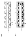
- Fig. 1a a plan view of a printed circuit board with recesses according to the invention
- Fig. 1b a plan view of the circuit board Fig. 1a , with soldered LEDs, arranged over a heat sink,
- Fig. 1c a side view of the LED module according to the invention
- FIG. 2 a side sectional view of a first manufacturing stage of the LED module according to the invention, with LEDs soldered directly over the recesses, FIG.
- Fig. 1e a side sectional view as a snapshot during the impressions of the LEDs as a consequence of the situation in Fig. 1d shown item
- Fig. 1f a side sectional view of the finished LED module after the in Fig. 1e shown production situation
- Fig. 2 a circuit diagram of a lighting device according to the invention, which manages five LED modules with the common control
- Fig. 3 a circuit diagram of a lighting device according to the invention, which manages five LED modules according to the invention with individual controls, wherein the Einzelsteu tions via two alternative current / voltage sources are operable,
- Fig. 4 a circuit diagram of a control device according to the invention Steue, which is operatively coupled to an LED module.
- the device according to the invention relates to a controlled LED module which has an electronic control device which can be coupled to a current / voltage source.
- the LED module has a printed circuit board on which a plurality of LED elements with an LED comprising at least one LED sheath and one each extending from the bottom of the LED element extending anode leg and a cathode leg in a series circuit on the circuit board, which is electronically coupled to the control device, are mounted on the circuit board by the anode and cathode legs are soldered to the LED on the circuit board, so that electronic contact is made to the adjacent LEDs.
- a printed circuit board heat sink is arranged below the printed circuit board.
- a recess is provided which is adapted to receive the underside of the LED mold so that it rests on the printed circuit board heat sink over its entire surface and dissipates heat.
- the LED element itself is designed so that it includes not only the LED but a separate LED heat sink. This is arranged on the underside of the LED sheath, so that the contact of the underside of the LED element is made with the conductor heat sink via the LED heat sink.
- Such an LED element is in Fig. 1c
- the printed circuit board 3 is arranged above the printed circuit board heat sink 6 with cooling fins 6 '.
- the circuit board 3 is screwed by means of screws 8 to the heat sink 6.
- the heat sink 6 has at its boundary a recess, which allows to accommodate the controller 10 in the heat sink 6.
- six LEDs soldered in series with sheath 2 are shown, the anode legs 2 'and cathode legs 2 "via corresponding Connections are soldered to the circuit board 3 and form a series connection.
- a durable and robust LED module is thereby created, since the cooling in the device is improved.
- the improved cooling of the device results from the fact that the circuit board 3 has a recess at each point at which a LED element with sheath is positioned.
- Fig. 1a This is going out Fig. 1a can be seen:
- the circuit board 3 can be seen in a prepared structure. It has the recesses 4 and also the holes 8 'for the later receiving the screws 8 for mounting the circuit board 3 on the cooling element 6, see Fig. 1b , up. There, all necessary lines for providing the series connection are prepared, as they are known in the art.
- the intended LED heat sink 5, such as in Fig. 1f and 1c can be seen, with its underside over the entire surface of the heat sink 6, which is only possible by the fact that the circuit board 3 has the corresponding recesses 4.
- the method of manufacturing the LED modules is carried out as follows:
- the LEDs with sheath 2 heatsink 5 directly contact the heat sink 6, which is designed with cooling fins 6 'for ideal convective warm air discharge.
- This contact is made by first placing the printed circuit board as shown in Fig. 1a shown is prepared. That is, the recesses 4 are created on the otherwise prepared circuit board 3. Then, the LED elements are soldered onto the circuit board, so that their anode leg 2 'and its cathode leg 2 "contact already provided on the circuit board 3 conductor sections, and therefore results in the desired electrical coupling to provide the series connection.
- Fig. 1d shows a section of the subject to this process step:
- the heat sink 5 of the LED 2 are significantly spaced from a base on which the circuit board is located.
- Fig. 1e shows, is now exerted in the direction of an arrow a pressure on the festgelöteten LEDs, so that they are all pressed simultaneously into the recesses 4.
- the respective anode legs 2 'and cathodes 2 "give way, they receive, as Fig. 1e and f show a slight kink.
- the heatsink are pressed into the circuit board 3.
- the printed circuit board can be arranged over the printed circuit board cooling body 6 and fastened by means of the screws 8. It should be provided in advance that also the connecting wires 9, which ultimately establish the connection to the controller 10, see Fig. 1c , soldered at the appropriate place and through the circuit board down in the direction of the control, which also finds room in the heat sink 6, are performed. Now, the electronic connections of the connecting wires 9 between the circuit board 3 and the optimally positioned thereon LEDs 2 with heat sinks 5 and the controller 10 can be made.
- the electronic control device 10 used for controlling the LED modules 1, as described in US Pat Fig. 4 2, shown in the dashed box, includes an input 18 to a power source, a switchable capacitor 12, a supply voltage regulator 13, two resistors 14, and a DC chopper 16, here configured as a DC-DC LED driver 16.
- the supply voltage regulator 13 is connected via the two resistors 14 to the DC-DC converter 16 and forms a stable voltage node 15 at the input to the DC-DC converter 16.
- the electronic control device 10 is electronically coupled to the LED module 1 via the connecting wires 9.
- Fig. 4 shown embodiment of the control are four fast Schottky diodes 11 in a bridge circuit.
- the capacitor which, if present at the input AC voltage smoothes the harmonic, this results in a universally usable current / voltage input 18.
- the applied voltage can therefore both a DC voltage and a square, a sine, a triangle - or be an AC voltage.
- the supply voltage regulator 13 operates precisely and forms a very stable voltage node with the resistors 14, of which the second is a varistor in the present case and provides a dimming function the DC-DC LED driver 16. This serves as a kind of converter.
- the current-voltage characteristic curve obtained in its operation leads, due to its width, to a current-voltage characteristic control of the device.
- the circuit can be operated with 24 volts DC or AC voltage and, since it is voltage-controlled, lead to a continuously adjustable light intensity of the white light emitting LED module.
- an efficient and economical power supply of the LED module is achieved and by the provided white light, which, unlike white light in fluorescent tubes does not flicker, it can be used in many ways.
- the improved cooling results in a longer life of the LEDs with very little energy consumption.
- Fig. 2 and 3 show, it is possible to control a number of LED modules, which was arbitrarily selected at five, via a common electronic controller 10 '.
- a mains voltage of 230 volts is provided via a mains supply 2 'and a mains dimmer 40 is in contact with the common control unit 10', which activates the five LED modules 1.
- the alternative embodiment which is in Fig. 3 shown, shows two alternative energy sources: First, the connection to a power grid 20 ', in the dashed box represents done with the fed 230 volts through the power dimmer 40 and the transformer 30th Finally, as a DC or AC voltage of 24 to 36 volts in the provided with the individual controls 10 modules 1 are passed. Another power source is the accumulator 20, which can be switched on alternatively.
- the external potentiometer 40 respectively by the power dimmer 40, the electronic with the individual controls whose voltage nodes are connected to the DC-DC LED driver, an external dimming can be done.
- the energy obtained by means of a solar panel can be temporarily fed into lighting devices, such as can be used as street lights, in the subway, in hospitals or as therapy lighting.
- each individual LED module can be operated separately, resulting in a special user-friendliness, since the light intensity is selectable
- the pleasant white continuous light does not flicker and is therefore much more pleasant than the light of fluorescent or energy-saving bulbs; It is also infinitely dimmable.
- the total energy consumption is very low.
- the color temperature of the light with about 5,000 to 5,500 Kelvin corresponds to a quality of light, as the sun has. This creates a pleasant white light.
Landscapes
- Engineering & Computer Science (AREA)
- General Engineering & Computer Science (AREA)
- Microelectronics & Electronic Packaging (AREA)
- Physics & Mathematics (AREA)
- Optics & Photonics (AREA)
- Arrangement Of Elements, Cooling, Sealing, Or The Like Of Lighting Devices (AREA)
Applications Claiming Priority (1)
| Application Number | Priority Date | Filing Date | Title |
|---|---|---|---|
| DE102009037919A DE102009037919A1 (de) | 2009-08-19 | 2009-08-19 | LED-Modul, Verfahren zu dessen Herstellung und LED-Beleuchtungsvorrichtung |
Publications (2)
| Publication Number | Publication Date |
|---|---|
| EP2287519A2 true EP2287519A2 (fr) | 2011-02-23 |
| EP2287519A3 EP2287519A3 (fr) | 2011-11-09 |
Family
ID=43216384
Family Applications (1)
| Application Number | Title | Priority Date | Filing Date |
|---|---|---|---|
| EP10008609A Withdrawn EP2287519A3 (fr) | 2009-08-19 | 2010-08-18 | Module DEL, son procédé de fabrication et dispositif d'éclairage à DEL |
Country Status (2)
| Country | Link |
|---|---|
| EP (1) | EP2287519A3 (fr) |
| DE (1) | DE102009037919A1 (fr) |
Cited By (5)
| Publication number | Priority date | Publication date | Assignee | Title |
|---|---|---|---|---|
| CN103499079A (zh) * | 2013-10-10 | 2014-01-08 | 昆山纯柏精密五金有限公司 | 一种led模块散热器加工方法 |
| DE102016104342A1 (de) * | 2016-03-09 | 2017-09-14 | Süd Solar GmbH | Beleuchtungsmodul, Lampe und Straßen- oder Wegleuchte |
| DE102016221522A1 (de) * | 2016-11-03 | 2018-05-03 | Jenoptik Polymer Systems Gmbh | LED-Leuchte |
| US10859215B2 (en) | 2017-02-27 | 2020-12-08 | Robert Bentley Chelf | Low voltage LED filament array lighting |
| USD913570S1 (en) | 2017-04-24 | 2021-03-16 | Robert Bentley Chelf | Filament-style LED array light |
Families Citing this family (2)
| Publication number | Priority date | Publication date | Assignee | Title |
|---|---|---|---|---|
| DE202012009365U1 (de) | 2012-09-28 | 2014-01-07 | Daycar Consulting Ag | LED-Leuchte |
| DE102014220656A1 (de) * | 2014-03-27 | 2015-10-01 | Tridonic Gmbh & Co Kg | LED-Modul mit integrierter Stromsteuerung |
Citations (3)
| Publication number | Priority date | Publication date | Assignee | Title |
|---|---|---|---|---|
| DE202007008258U1 (de) | 2007-04-30 | 2007-10-31 | Lumitech Produktion Und Entwicklung Gmbh | LED-Leuchtmittel |
| DE102007043355A1 (de) | 2007-09-12 | 2009-03-19 | Lumitech Produktion Und Entwicklung Gmbh | LED-Modul, LED-Leuchtmittel und LED Leuchte für die energie-effiziente Wiedergabe von weißem Licht |
| DE202008017219U1 (de) | 2008-08-05 | 2009-04-16 | Pyroswift Holding Co., Ltd., Wanchai | Leuchtdioden-Lichtaggregat |
Family Cites Families (7)
| Publication number | Priority date | Publication date | Assignee | Title |
|---|---|---|---|---|
| US20050001562A1 (en) * | 2003-07-02 | 2005-01-06 | 911Ep, Inc. | LED compensation circuit |
| TWI333576B (en) * | 2005-08-17 | 2010-11-21 | Au Optronics Corp | Bottom lighting module |
| CN100464411C (zh) * | 2005-10-20 | 2009-02-25 | 富准精密工业(深圳)有限公司 | 发光二极管封装结构及封装方法 |
| TWI326131B (en) * | 2006-07-05 | 2010-06-11 | Neobulb Technologies Inc | Illuminating equipment of high-power and clustered light-emitting diodes coupled to high efficiency heat-spreading and heat-dissipating module |
| CN101296564B (zh) * | 2007-04-27 | 2010-11-10 | 富士迈半导体精密工业(上海)有限公司 | 具良好散热性能的光源模组 |
| KR101555894B1 (ko) * | 2007-05-04 | 2015-09-30 | 코닌클리케 필립스 엔.브이. | 열 관리를 위한 led 기반 설비들 및 관련 방법들 |
| WO2008137460A2 (fr) * | 2007-05-07 | 2008-11-13 | Koninklijke Philips Electronics N V | Appareil d'éclairage à del à haut facteur de puissance et procédés associés |
-
2009
- 2009-08-19 DE DE102009037919A patent/DE102009037919A1/de not_active Ceased
-
2010
- 2010-08-18 EP EP10008609A patent/EP2287519A3/fr not_active Withdrawn
Patent Citations (3)
| Publication number | Priority date | Publication date | Assignee | Title |
|---|---|---|---|---|
| DE202007008258U1 (de) | 2007-04-30 | 2007-10-31 | Lumitech Produktion Und Entwicklung Gmbh | LED-Leuchtmittel |
| DE102007043355A1 (de) | 2007-09-12 | 2009-03-19 | Lumitech Produktion Und Entwicklung Gmbh | LED-Modul, LED-Leuchtmittel und LED Leuchte für die energie-effiziente Wiedergabe von weißem Licht |
| DE202008017219U1 (de) | 2008-08-05 | 2009-04-16 | Pyroswift Holding Co., Ltd., Wanchai | Leuchtdioden-Lichtaggregat |
Cited By (11)
| Publication number | Priority date | Publication date | Assignee | Title |
|---|---|---|---|---|
| CN103499079A (zh) * | 2013-10-10 | 2014-01-08 | 昆山纯柏精密五金有限公司 | 一种led模块散热器加工方法 |
| DE102016104342A1 (de) * | 2016-03-09 | 2017-09-14 | Süd Solar GmbH | Beleuchtungsmodul, Lampe und Straßen- oder Wegleuchte |
| DE102016104342B4 (de) | 2016-03-09 | 2019-04-18 | SLB GmbH | Beleuchtungsmodul und Straßen- oder Wegleuchte |
| DE102016221522A1 (de) * | 2016-11-03 | 2018-05-03 | Jenoptik Polymer Systems Gmbh | LED-Leuchte |
| WO2018082999A1 (fr) | 2016-11-03 | 2018-05-11 | Jenoptik Polymer Systems Gmbh | Éclairage à led |
| DE102016221522B4 (de) | 2016-11-03 | 2019-04-25 | Jenoptik Polymer Systems Gmbh | LED-Leuchte |
| US10859215B2 (en) | 2017-02-27 | 2020-12-08 | Robert Bentley Chelf | Low voltage LED filament array lighting |
| US11732846B2 (en) | 2017-02-27 | 2023-08-22 | Robert Bentley Chelf | Low voltage LED filament array lighting |
| US12140277B2 (en) | 2017-02-27 | 2024-11-12 | Robert Bentley Chelf | Low voltage LED filament array lighting |
| USD913570S1 (en) | 2017-04-24 | 2021-03-16 | Robert Bentley Chelf | Filament-style LED array light |
| USD1016371S1 (en) | 2017-04-24 | 2024-02-27 | Robert Bentley Chelf | Filament-style LED array light |
Also Published As
| Publication number | Publication date |
|---|---|
| DE102009037919A1 (de) | 2011-02-24 |
| EP2287519A3 (fr) | 2011-11-09 |
Similar Documents
| Publication | Publication Date | Title |
|---|---|---|
| DE102010008876B4 (de) | Lichtquelle mit Array-LEDs zum direkten Betrieb am Wechselspannungsnetz und Herstellungsverfahren hierfür | |
| EP2287519A2 (fr) | Module DEL, son procédé de fabrication et dispositif d'éclairage à DEL | |
| DE102010030639B4 (de) | Leuchtvorrichtung mit beweglichem Konverterelement | |
| EP2198196B1 (fr) | Lampe | |
| WO2009021695A1 (fr) | Lampe à del | |
| DE202010001128U1 (de) | LED-Leuchtvorrichtung mit größerem Leuchtwinkel | |
| DE112012003338T5 (de) | Wechselstrom-Gleichstrom-LED-Beleuchtungsvorrichtungen, -Systeme und -Verfahren | |
| DE202009017522U1 (de) | LED-Einbauleuchte mit Kühlkörper | |
| DE102008036020A1 (de) | Optoelektronisches Modul und Beleuchtungsvorrichtung | |
| DE112013001316T5 (de) | LED-Anordnung für den Ersatz von Leuchtstoffröhren | |
| DE202009016457U1 (de) | LED-Einbauleuchte mit Wärmeableitung | |
| DE10230103B4 (de) | Stromversorgung für Lumineszenzdioden | |
| DE112009001774B4 (de) | Leuchtmittel mit LED, Notwegbeleuchtung und Verfahren zum gleichmäßigen Ausleuchten einer Fläche | |
| EP2541139B1 (fr) | Module d' éclairage à DEL | |
| WO2010115395A1 (fr) | Unité d'éclairage | |
| DE102009009520A1 (de) | Steckmodul für ein modular aufgebautes Leuchtmittel, Leuchtmodul für das Leuchtmittel sowie modular aufgebautes Leuchtmittel | |
| DE212013000310U1 (de) | LED-Photovoltaik-Modul | |
| WO2009115063A1 (fr) | Agencement de lampe et procédés d'émission de lumière | |
| DE102017114525B4 (de) | Beleuchtungsvorrichtung, beleuchtungskörper, beleuchtungssystem und programm | |
| DE202016107013U1 (de) | Leuchteinheit, insbesondere für eine Schirmleuchte, und Leuchte, insbesondere Schirmleuchte, mit einer Leuchteinheit | |
| DE102016104342B4 (de) | Beleuchtungsmodul und Straßen- oder Wegleuchte | |
| DE10262387B3 (de) | Stromversorgung für Lumineszenzdioden | |
| DE202009016460U1 (de) | LED-Leuchtvorrichtung | |
| DE202008009372U1 (de) | Hochleistungs-LED-Lampe | |
| WO2014063975A1 (fr) | Dispositif d'éclairage pourvu d'un corps de refroidissement et au moins d'une source lumineuse semi-conductrice |
Legal Events
| Date | Code | Title | Description |
|---|---|---|---|
| PUAI | Public reference made under article 153(3) epc to a published international application that has entered the european phase |
Free format text: ORIGINAL CODE: 0009012 |
|
| AK | Designated contracting states |
Kind code of ref document: A2 Designated state(s): AL AT BE BG CH CY CZ DE DK EE ES FI FR GB GR HR HU IE IS IT LI LT LU LV MC MK MT NL NO PL PT RO SE SI SK SM TR |
|
| AX | Request for extension of the european patent |
Extension state: BA ME RS |
|
| PUAL | Search report despatched |
Free format text: ORIGINAL CODE: 0009013 |
|
| AK | Designated contracting states |
Kind code of ref document: A3 Designated state(s): AL AT BE BG CH CY CZ DE DK EE ES FI FR GB GR HR HU IE IS IT LI LT LU LV MC MK MT NL NO PL PT RO SE SI SK SM TR |
|
| AX | Request for extension of the european patent |
Extension state: BA ME RS |
|
| RIC1 | Information provided on ipc code assigned before grant |
Ipc: F21V 23/00 20060101ALN20110930BHEP Ipc: F21S 2/00 20060101ALN20110930BHEP Ipc: F21W 131/00 20060101ALN20110930BHEP Ipc: F21W 111/02 20060101ALN20110930BHEP Ipc: F21Y 101/02 20060101ALN20110930BHEP Ipc: F21W 131/103 20060101ALN20110930BHEP Ipc: F21W 131/20 20060101ALN20110930BHEP Ipc: F21V 29/00 20060101ALN20110930BHEP Ipc: F21K 99/00 20100101AFI20110930BHEP |
|
| 17P | Request for examination filed |
Effective date: 20120307 |
|
| RIC1 | Information provided on ipc code assigned before grant |
Ipc: F21W 111/02 20060101ALN20131021BHEP Ipc: F21V 23/00 20060101ALN20131021BHEP Ipc: F21Y 101/02 20060101ALN20131021BHEP Ipc: F21S 2/00 20060101ALN20131021BHEP Ipc: F21V 29/00 20060101ALN20131021BHEP Ipc: F21W 131/00 20060101ALN20131021BHEP Ipc: F21W 131/20 20060101ALN20131021BHEP Ipc: F21K 99/00 20100101AFI20131021BHEP Ipc: F21W 131/103 20060101ALN20131021BHEP |
|
| RIC1 | Information provided on ipc code assigned before grant |
Ipc: F21V 23/00 20060101ALN20140211BHEP Ipc: F21W 131/103 20060101ALN20140211BHEP Ipc: F21W 131/00 20060101ALN20140211BHEP Ipc: F21V 29/00 20060101ALN20140211BHEP Ipc: F21W 111/02 20060101ALN20140211BHEP Ipc: F21K 99/00 20100101AFI20140211BHEP Ipc: F21S 2/00 20060101ALN20140211BHEP Ipc: F21W 131/20 20060101ALN20140211BHEP Ipc: F21Y 101/02 20060101ALN20140211BHEP |
|
| RIC1 | Information provided on ipc code assigned before grant |
Ipc: F21V 23/00 20060101ALN20140224BHEP Ipc: F21S 2/00 20060101ALN20140224BHEP Ipc: F21W 131/103 20060101ALN20140224BHEP Ipc: F21W 131/20 20060101ALN20140224BHEP Ipc: F21V 29/00 20060101ALN20140224BHEP Ipc: F21W 111/02 20060101ALN20140224BHEP Ipc: F21W 131/00 20060101ALN20140224BHEP Ipc: F21Y 101/02 20060101ALN20140224BHEP Ipc: F21K 99/00 20100101AFI20140224BHEP |
|
| 17Q | First examination report despatched |
Effective date: 20140317 |
|
| RIC1 | Information provided on ipc code assigned before grant |
Ipc: F21W 131/00 20060101ALN20140414BHEP Ipc: F21W 131/20 20060101ALN20140414BHEP Ipc: F21W 131/103 20060101ALN20140414BHEP Ipc: F21K 99/00 20100101AFI20140414BHEP Ipc: F21Y 101/02 20060101ALN20140414BHEP Ipc: F21V 29/00 20060101ALN20140414BHEP Ipc: F21V 23/00 20060101ALN20140414BHEP Ipc: F21W 111/02 20060101ALN20140414BHEP Ipc: F21S 2/00 20060101ALN20140414BHEP |
|
| RIC1 | Information provided on ipc code assigned before grant |
Ipc: F21W 131/103 20060101ALN20140514BHEP Ipc: F21K 99/00 20100101AFI20140514BHEP Ipc: F21Y 101/02 20060101ALN20140514BHEP Ipc: F21V 29/00 20060101ALN20140514BHEP Ipc: F21W 131/00 20060101ALN20140514BHEP Ipc: F21S 2/00 20060101ALN20140514BHEP Ipc: F21W 131/20 20060101ALN20140514BHEP Ipc: F21V 23/00 20060101ALN20140514BHEP Ipc: F21W 111/02 20060101ALN20140514BHEP |
|
| GRAP | Despatch of communication of intention to grant a patent |
Free format text: ORIGINAL CODE: EPIDOSNIGR1 |
|
| INTG | Intention to grant announced |
Effective date: 20140620 |
|
| RIC1 | Information provided on ipc code assigned before grant |
Ipc: F21V 29/00 20060101ALN20140611BHEP Ipc: F21S 2/00 20060101ALN20140611BHEP Ipc: F21W 131/103 20060101ALN20140611BHEP Ipc: F21K 99/00 20100101AFI20140611BHEP Ipc: F21W 131/20 20060101ALN20140611BHEP Ipc: F21W 111/02 20060101ALN20140611BHEP Ipc: F21V 23/00 20060101ALN20140611BHEP Ipc: F21W 131/00 20060101ALN20140611BHEP Ipc: F21Y 101/02 20060101ALN20140611BHEP |
|
| GRAS | Grant fee paid |
Free format text: ORIGINAL CODE: EPIDOSNIGR3 |
|
| STAA | Information on the status of an ep patent application or granted ep patent |
Free format text: STATUS: THE APPLICATION IS DEEMED TO BE WITHDRAWN |
|
| 18D | Application deemed to be withdrawn |
Effective date: 20141031 |