EP2287524A1 - Appareil d'éclairage et son procédé de fabrication - Google Patents
Appareil d'éclairage et son procédé de fabrication Download PDFInfo
- Publication number
- EP2287524A1 EP2287524A1 EP10251460A EP10251460A EP2287524A1 EP 2287524 A1 EP2287524 A1 EP 2287524A1 EP 10251460 A EP10251460 A EP 10251460A EP 10251460 A EP10251460 A EP 10251460A EP 2287524 A1 EP2287524 A1 EP 2287524A1
- Authority
- EP
- European Patent Office
- Prior art keywords
- thermally conductive
- casing
- led
- lighting apparatus
- devices
- Prior art date
- Legal status (The legal status is an assumption and is not a legal conclusion. Google has not performed a legal analysis and makes no representation as to the accuracy of the status listed.)
- Withdrawn
Links
Images


Classifications
-
- F—MECHANICAL ENGINEERING; LIGHTING; HEATING; WEAPONS; BLASTING
- F21—LIGHTING
- F21S—NON-PORTABLE LIGHTING DEVICES; SYSTEMS THEREOF; VEHICLE LIGHTING DEVICES SPECIALLY ADAPTED FOR VEHICLE EXTERIORS
- F21S8/00—Lighting devices intended for fixed installation
- F21S8/03—Lighting devices intended for fixed installation of surface-mounted type
- F21S8/033—Lighting devices intended for fixed installation of surface-mounted type the surface being a wall or like vertical structure, e.g. building facade
-
- F—MECHANICAL ENGINEERING; LIGHTING; HEATING; WEAPONS; BLASTING
- F21—LIGHTING
- F21V—FUNCTIONAL FEATURES OR DETAILS OF LIGHTING DEVICES OR SYSTEMS THEREOF; STRUCTURAL COMBINATIONS OF LIGHTING DEVICES WITH OTHER ARTICLES, NOT OTHERWISE PROVIDED FOR
- F21V19/00—Fastening of light sources or lamp holders
- F21V19/001—Fastening of light sources or lamp holders the light sources being semiconductors devices, e.g. LEDs
-
- F—MECHANICAL ENGINEERING; LIGHTING; HEATING; WEAPONS; BLASTING
- F21—LIGHTING
- F21V—FUNCTIONAL FEATURES OR DETAILS OF LIGHTING DEVICES OR SYSTEMS THEREOF; STRUCTURAL COMBINATIONS OF LIGHTING DEVICES WITH OTHER ARTICLES, NOT OTHERWISE PROVIDED FOR
- F21V15/00—Protecting lighting devices from damage
- F21V15/01—Housings, e.g. material or assembling of housing parts
-
- F—MECHANICAL ENGINEERING; LIGHTING; HEATING; WEAPONS; BLASTING
- F21—LIGHTING
- F21V—FUNCTIONAL FEATURES OR DETAILS OF LIGHTING DEVICES OR SYSTEMS THEREOF; STRUCTURAL COMBINATIONS OF LIGHTING DEVICES WITH OTHER ARTICLES, NOT OTHERWISE PROVIDED FOR
- F21V19/00—Fastening of light sources or lamp holders
- F21V19/001—Fastening of light sources or lamp holders the light sources being semiconductors devices, e.g. LEDs
- F21V19/003—Fastening of light source holders, e.g. of circuit boards or substrates holding light sources
- F21V19/0055—Fastening of light source holders, e.g. of circuit boards or substrates holding light sources by screwing
-
- F—MECHANICAL ENGINEERING; LIGHTING; HEATING; WEAPONS; BLASTING
- F21—LIGHTING
- F21V—FUNCTIONAL FEATURES OR DETAILS OF LIGHTING DEVICES OR SYSTEMS THEREOF; STRUCTURAL COMBINATIONS OF LIGHTING DEVICES WITH OTHER ARTICLES, NOT OTHERWISE PROVIDED FOR
- F21V19/00—Fastening of light sources or lamp holders
- F21V19/04—Fastening of light sources or lamp holders with provision for changing light source, e.g. turret
-
- F—MECHANICAL ENGINEERING; LIGHTING; HEATING; WEAPONS; BLASTING
- F21—LIGHTING
- F21V—FUNCTIONAL FEATURES OR DETAILS OF LIGHTING DEVICES OR SYSTEMS THEREOF; STRUCTURAL COMBINATIONS OF LIGHTING DEVICES WITH OTHER ARTICLES, NOT OTHERWISE PROVIDED FOR
- F21V19/00—Fastening of light sources or lamp holders
- F21V19/04—Fastening of light sources or lamp holders with provision for changing light source, e.g. turret
- F21V19/047—Fastening of light sources or lamp holders with provision for changing light source, e.g. turret by using spare light sources comprised in or attached to the lighting device and being intended to replace a defect light source by manual mounting
-
- F—MECHANICAL ENGINEERING; LIGHTING; HEATING; WEAPONS; BLASTING
- F21—LIGHTING
- F21V—FUNCTIONAL FEATURES OR DETAILS OF LIGHTING DEVICES OR SYSTEMS THEREOF; STRUCTURAL COMBINATIONS OF LIGHTING DEVICES WITH OTHER ARTICLES, NOT OTHERWISE PROVIDED FOR
- F21V21/00—Supporting, suspending, or attaching arrangements for lighting devices; Hand grips
- F21V21/005—Supporting, suspending, or attaching arrangements for lighting devices; Hand grips for several lighting devices in an end-to-end arrangement, i.e. light tracks
-
- F—MECHANICAL ENGINEERING; LIGHTING; HEATING; WEAPONS; BLASTING
- F21—LIGHTING
- F21V—FUNCTIONAL FEATURES OR DETAILS OF LIGHTING DEVICES OR SYSTEMS THEREOF; STRUCTURAL COMBINATIONS OF LIGHTING DEVICES WITH OTHER ARTICLES, NOT OTHERWISE PROVIDED FOR
- F21V29/00—Protecting lighting devices from thermal damage; Cooling or heating arrangements specially adapted for lighting devices or systems
- F21V29/50—Cooling arrangements
- F21V29/502—Cooling arrangements characterised by the adaptation for cooling of specific components
- F21V29/507—Cooling arrangements characterised by the adaptation for cooling of specific components of means for protecting lighting devices from damage, e.g. housings
-
- F—MECHANICAL ENGINEERING; LIGHTING; HEATING; WEAPONS; BLASTING
- F21—LIGHTING
- F21V—FUNCTIONAL FEATURES OR DETAILS OF LIGHTING DEVICES OR SYSTEMS THEREOF; STRUCTURAL COMBINATIONS OF LIGHTING DEVICES WITH OTHER ARTICLES, NOT OTHERWISE PROVIDED FOR
- F21V29/00—Protecting lighting devices from thermal damage; Cooling or heating arrangements specially adapted for lighting devices or systems
- F21V29/50—Cooling arrangements
- F21V29/70—Cooling arrangements characterised by passive heat-dissipating elements, e.g. heat-sinks
-
- F—MECHANICAL ENGINEERING; LIGHTING; HEATING; WEAPONS; BLASTING
- F21—LIGHTING
- F21V—FUNCTIONAL FEATURES OR DETAILS OF LIGHTING DEVICES OR SYSTEMS THEREOF; STRUCTURAL COMBINATIONS OF LIGHTING DEVICES WITH OTHER ARTICLES, NOT OTHERWISE PROVIDED FOR
- F21V29/00—Protecting lighting devices from thermal damage; Cooling or heating arrangements specially adapted for lighting devices or systems
- F21V29/50—Cooling arrangements
- F21V29/70—Cooling arrangements characterised by passive heat-dissipating elements, e.g. heat-sinks
- F21V29/74—Cooling arrangements characterised by passive heat-dissipating elements, e.g. heat-sinks with fins or blades
- F21V29/76—Cooling arrangements characterised by passive heat-dissipating elements, e.g. heat-sinks with fins or blades with essentially identical parallel planar fins or blades, e.g. with comb-like cross-section
- F21V29/763—Cooling arrangements characterised by passive heat-dissipating elements, e.g. heat-sinks with fins or blades with essentially identical parallel planar fins or blades, e.g. with comb-like cross-section the planes containing the fins or blades having the direction of the light emitting axis
-
- F—MECHANICAL ENGINEERING; LIGHTING; HEATING; WEAPONS; BLASTING
- F21—LIGHTING
- F21V—FUNCTIONAL FEATURES OR DETAILS OF LIGHTING DEVICES OR SYSTEMS THEREOF; STRUCTURAL COMBINATIONS OF LIGHTING DEVICES WITH OTHER ARTICLES, NOT OTHERWISE PROVIDED FOR
- F21V29/00—Protecting lighting devices from thermal damage; Cooling or heating arrangements specially adapted for lighting devices or systems
- F21V29/85—Protecting lighting devices from thermal damage; Cooling or heating arrangements specially adapted for lighting devices or systems characterised by the material
- F21V29/87—Organic material, e.g. filled polymer composites; Thermo-conductive additives or coatings therefor
-
- F—MECHANICAL ENGINEERING; LIGHTING; HEATING; WEAPONS; BLASTING
- F21—LIGHTING
- F21V—FUNCTIONAL FEATURES OR DETAILS OF LIGHTING DEVICES OR SYSTEMS THEREOF; STRUCTURAL COMBINATIONS OF LIGHTING DEVICES WITH OTHER ARTICLES, NOT OTHERWISE PROVIDED FOR
- F21V29/00—Protecting lighting devices from thermal damage; Cooling or heating arrangements specially adapted for lighting devices or systems
- F21V29/85—Protecting lighting devices from thermal damage; Cooling or heating arrangements specially adapted for lighting devices or systems characterised by the material
- F21V29/89—Metals
-
- H—ELECTRICITY
- H10—SEMICONDUCTOR DEVICES; ELECTRIC SOLID-STATE DEVICES NOT OTHERWISE PROVIDED FOR
- H10H—INORGANIC LIGHT-EMITTING SEMICONDUCTOR DEVICES HAVING POTENTIAL BARRIERS
- H10H20/00—Individual inorganic light-emitting semiconductor devices having potential barriers, e.g. light-emitting diodes [LED]
- H10H20/80—Constructional details
- H10H20/85—Packages
- H10H20/857—Interconnections, e.g. lead-frames, bond wires or solder balls
-
- F—MECHANICAL ENGINEERING; LIGHTING; HEATING; WEAPONS; BLASTING
- F21—LIGHTING
- F21W—INDEXING SCHEME ASSOCIATED WITH SUBCLASSES F21K, F21L, F21S and F21V, RELATING TO USES OR APPLICATIONS OF LIGHTING DEVICES OR SYSTEMS
- F21W2131/00—Use or application of lighting devices or systems not provided for in codes F21W2102/00-F21W2121/00
- F21W2131/10—Outdoor lighting
- F21W2131/105—Outdoor lighting of arenas or the like
-
- F—MECHANICAL ENGINEERING; LIGHTING; HEATING; WEAPONS; BLASTING
- F21—LIGHTING
- F21Y—INDEXING SCHEME ASSOCIATED WITH SUBCLASSES F21K, F21L, F21S and F21V, RELATING TO THE FORM OR THE KIND OF THE LIGHT SOURCES OR OF THE COLOUR OF THE LIGHT EMITTED
- F21Y2105/00—Planar light sources
- F21Y2105/10—Planar light sources comprising a two-dimensional [2D] array of point-like light-generating elements
- F21Y2105/14—Planar light sources comprising a two-dimensional [2D] array of point-like light-generating elements characterised by the overall shape of the two-dimensional [2D] array
- F21Y2105/16—Planar light sources comprising a two-dimensional [2D] array of point-like light-generating elements characterised by the overall shape of the two-dimensional [2D] array square or rectangular, e.g. for light panels
-
- F—MECHANICAL ENGINEERING; LIGHTING; HEATING; WEAPONS; BLASTING
- F21—LIGHTING
- F21Y—INDEXING SCHEME ASSOCIATED WITH SUBCLASSES F21K, F21L, F21S and F21V, RELATING TO THE FORM OR THE KIND OF THE LIGHT SOURCES OR OF THE COLOUR OF THE LIGHT EMITTED
- F21Y2115/00—Light-generating elements of semiconductor light sources
- F21Y2115/10—Light-emitting diodes [LED]
Definitions
- the present invention relates to lighting apparatus, of the type having a plurality of light emitting diode (LED) devices configured to emit light in response to receiving electrical power.
- LED light emitting diode
- lighting apparatus of the aforesaid type, characterised by: a casing moulded from an electrically isolating and thermally conductive plastics material; and a plurality of metallic assemblies, wherein each on eof said metallic assemblies provides electrical power to a respective one of said LED devices, conducts heat from its respective LED device to said casing and is directly supported by said casing.
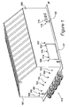
- FIG. 1 An external area illuminated by an embodiment of the present invention is illustrated in Figure 1 .
- the environment illustrates a warehouse 101 in which a first set of security cameras 102, 103 and 104 are mounted on a first wall. On a second wall 105 a second set of security cameras 106 and 107 are provided.
- Lighting apparatus embodying the present invention are attached to the first wall at locations 108, 109, 110, 111 and 112.
- Lighting apparatus 108 to 112 illuminate an area 113 where vehicles are parked, although it is possible this may not have been known initially when the lights 108 to 112 and cameras 102 to 104 were installed.
- there is clearer evidence as to which vehicles are parked in area 113.
- Lighting apparatus 114, 115 and 116 co-operate with video cameras 106 and 107 on the second wall 105. Vehicles enter the warehouse via door 117 but personal would be aware of the exact nature of the vehicles so using the warehouse in this way, therefore the video record is not so important. Consequently, a different type of illumination may be deployed for lighting systems 114 to 116, compared to lighting systems 108 to 112.
- Lighting 118 and 119 effectively providing illumination above a door 120.
- Lighting 118 and 119 is not provided for security purposes, there is no camera deployed with these lights, but the lighting is provided for safety reasons. Thus, the actual colour of the lighting is not so important provided that sufficient illumination is provided in the region of door 120.
- the requirements for the lighting systems shown in Figure 1 may change over a period of time.
- infrared lighting which is visible to the video cameras but does not create unnecessary light pollution.
- the actual colour of the emitted light is of little importance provided that the lighting is sufficiently bright.
- emphasis may be placed on lighting efficiency.
- white light will be required to ensure that the colour information is correctly recorded.
- the present invention facilitates the changing of individual LED devices within the lighting apparatus thereby allowing a change to be made to the type of light emitted relatively quickly and easily should the requirement for illumination in the space under consideration to change.
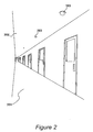
- FIG. 2 An internal area accessible to people of the type where an embodiment of the invention may be deployed, is illustrated in Figure 2 .
- a corridor 201 is shown providing access through a large building.
- the building is open to public access during part of the day, while being restricted at other times.
- lighting is provided by conventional lighting devices, possibly housed within a suspended ceiling 202.
- this conventional lighting would be considered excessive during times when access to the area is restricted but the absence of any lighting at all could create security related problems.
- the corridor 201 is fitted with security surveillance video cameras 203 which, although not requiring large amounts of light in order to be operational, do require a degree of lighting. The environment would therefore benefit from the inclusion of security lighting which would then operate in co-operation with video recording devices, including cameras 203.
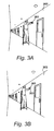
- An embodiment of the present invention is wall mounted so as to facilitate installation, repair and access. During the installation process, a mounting bracket 301 is secured firmly to a wall 302.
- lighting apparatus 303 is located upon bracket 201 such that its orientation may be adjusted and the lighting apparatus as a whole may be replaced.
- the lighting apparatus 301 includes a plurality of light emitting diode (LED) devices configured to emit light in response to receiving electrical power.
- the LED devices use substantially less electrical power than conventional incandescent lighting and typically operate between 12 volt and 24 volt.
- the lighting devices themselves may receive electrical power that is at this voltage or alternatively they may be supplied with mains electricity (110 volt to 240 volt) with circuitry being provided at the devices themselves to perform the necessary transformation to the lower voltage.
- circuitry is included for adjusting the degree of power supplied to each of the LED devices, often by a process of pulse width modulation as is well known in the art.
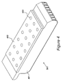
- Lighting apparatus 301 is shown in Figure 4 .
- the apparatus includes a casing 401 that is moulded from an electrically isolating and thermally conductive plastics material.
- Suitable examples for the plastics material are E2 thermally conductive liquid crystalline polymer; E3603 thermally conductive polyamide 4, 6; E3605 thermally conductive polyamide 4, 6; E4501 thermally conductive polycarbonate; E405 thermally conductive polycarbonate and E4507 thermally conductive polycarbonate.
- E2 thermally conductive liquid crystalline polymer E3603 thermally conductive polyamide 4, 6; E3605 thermally conductive polyamide 4, 6; E4501 thermally conductive polycarbonate; E405 thermally conductive polycarbonate and E4507 thermally conductive polycarbonate.
- E2 thermally conductive liquid crystalline polymer E3603 thermally conductive polyamide 4, 6; E3605 thermally conductive polyamide 4, 6; E4501 thermally conductive polycarbonate; E405 thermally conductive polycarbonate and E
- the apparatus is provided with a transparent cover plate 402 beneath which is arranged a matrix of light emitting diode devices, each of which may have an associated lens diffuser within the transparent cover plate 402.
- a plurality of metallic assemblies are restrained by the moulding so as to provide mechanical support for the LED devices, electrical connectivity and thermal heats transmission.
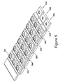
- the metallic assemblies are detailed in Figure 5 .
- a plurality of metallic assemblies are illustrated in Figure 5 , each one providing electrical power to a respective one of the LED devices.
- these metallic assemblies conduct heat away from their respective LED device such that this heat may be dissipated to atmosphere through the thermally conductive casing 401.
- Each assembly is directly supported by the casing 301 and the provision of these metallic assemblies allows each LED device to be individually replaced.
- LED replacement may occur due to degradation or alternatively LED replacement may be required if an alternative wavelength is required.
- the light emitting diodes may emit in the infra red spectrum, the visible spectrum, a portion of the visible spectrum (i.e. colored) and the ultra violet spectrum.
- the plurality of metallic assemblies shown in Figure 5 define a matrix of three groups with six assemblies within each group. Thus, there are a total of eighteen LED wafers 501 within the lighting apparatus. However, it should be appreciated that many alternative configurations could be deployed.
- Group 502 includes a first assembly 503, a second assembly 504, a third assembly 505, a fourth assembly 506, a fifth assembly 507 and a sixth assembly 508. This configuration is then repeated for a second group 509 and a third group 510.
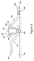
- each of the metallic assemblies includes an inclined bracket 601 having a based portion 602, an inclined portion 603 and a raised portion 604.
- the raised portion supports an LED subassembly 605.
- a first attached inclined bracket 508 is next to a second inclined bracket 509.
- the raised portion 604 of the second inclined bracket 509 is above the base portion 602 of the first inclined bracket 508.
- the base portion 602 of the first inclined bracket 508 lies between the raised portion 604 of the second inclined bracket 509 and the moulded casing.
- the base portion 602 includes a lower threaded hole 606.
- the raised portion 604 includes an upper non-threaded hole 607.
- the LED subassembly 605 is detailed in Figure 7 .
- the LED subassembly 605 includes an inner conductive element 701 which has an LED wafer 702 mounted thereon to provide thermal conduction of heat away from the LED wafer thereby allowing the LED wafer to operate at higher power ratings.
- a first electrical connection 703 is made between the LED wafer 702 and the inner electrically conductive element 701.
- the LED subassembly 605 also includes a coaxial insulating element 704 that may be constructed from substantially similar material to that of the moulded casing.
- the coaxial insulating element 704 is electrically insulating while being thermally conductive.
- the LED subassembly 605 also includes a coaxial outer conductive element 705 electrically insulated from the inner conducting elements 701. Furthermore, an electrical connection 706 is made between the LED wafer 702 and the coaxial outer conductive element 705.
- the coaxial insulating element 704 extends below the coaxial outer conductive element.
- the coaxial outer conductive element 704 is received within an upper hole 607 of an aligned pair and may be held firmly within this upper hole by the provision of an interference fit.
- the inner conductive element 701 extends below the coaxial insulating element 704 and includes a threaded portion 707. Threaded portion 707 engages with tapped hole 606 so as to secure each LED subassembly within the matrix of inclined brackets.
- the inclined metallic brackets shown in Figure 5 are arranged within a mould.
- a casing as shown in Figure 4 , is moulded around the inclined metallic brackets so as to support these inclined metallic brackets.
- the casing is moulded from an electrically insulating and thermally conductive plastics material.
- Individually supported light emitting diodes are then located within each of a respective one of the inclined metallic brackets.
- FIG 8 illustrates how electrical power is supplied to each of the plurality of light emitting diode devices contained within the lighting apparatus.
- a plurality of inclined metallic brackets are arranged in a matrix and for the purposes of this illustration, a first inclined bracket 801 is shown co-operating with a second inclined bracket 802 and an LED assembly 803.
- each inclined metallic bracket includes a base portion 602, an inclined portion 603 and a raised portion 604.
- the base portion 602 includes a tapped lower hole 606 and the raised portion 604 includes an upper hole 607 that has a larger diameter than the lower hole.
- a casing 401 is moulded around the inclined metallic brackets which then defines one or more groups.
- three groups 502, 509 and 510 are established.
- the brackets are serially connected, such that power is applied across the ends of each group and a plurality of groups are connected in parallel.
- the lower hole 606 of the first bracket 801 is located directly below the upper hole 607 of the second bracket 802, thereby defining a matrix of aligned holes.
- the moulded casing In production; the moulded casing is then removed from its mould, and, when so removed, the casing supports the brackets thereby electrically isolating them but providing thermal conductivity so as to dissipate heat generated by the LED devices.
- the moulded casing thereby provides a mechanical support for the devices and a heat sink for the devices.
- LED subassemblies 803 are inserted through respective aligned holes, with each of the LED subassemblies including an inner conductive element 701, a coaxial insulating element 704 and a coaxial outer conductive element 705.
- An LED wafer 702 is mechanically and electrically connected to the inner conductive element 701 to facilitate electrical transmission and heat transmission. As previously described, an electrical connection is also made between the outer conductive element 705 and the LED wafer 702.
- An electrical path is provided between a first end 806 of the group and a second end 807 of the group.
- a current path is provided along inclined bracket 802 which is in mechanical contact with the outer conducting element 705 and the coaxial insulating element 704.
- a secure mechanical interference fit is provided between the insulating element 704 and the outer conductor 705 but the presence of the insulating element 704 presents a direct electrical path between inclined bracket 802 and the inner conductor 701.
- the inner conductive element is terminated by a point 808 so as to embed the inner element within the plastic moulding 401, again enhancing thermal conductivity.
- Figure 5 shows three groups of six LED devices. However, it should be appreciated that other arrangements may be adopted in which elements are connected in series to define a group and groups are then connected in parallel.
- electrical power is received from a mains supply such that during deployment, as shown in Figure 3 , it is necessary for each lighting apparatus to be connected to this mains supply.
- the apparatus itself in an embodiment, includes procedures for rectifying the mains supply and controlling power input by a process of pulse width modulation.
Landscapes
- Engineering & Computer Science (AREA)
- General Engineering & Computer Science (AREA)
- Architecture (AREA)
- Non-Portable Lighting Devices Or Systems Thereof (AREA)
- Arrangement Of Elements, Cooling, Sealing, Or The Like Of Lighting Devices (AREA)
- Led Device Packages (AREA)
- Fastening Of Light Sources Or Lamp Holders (AREA)
Applications Claiming Priority (1)
| Application Number | Priority Date | Filing Date | Title |
|---|---|---|---|
| GB0914582.2A GB2472833B (en) | 2009-08-20 | 2009-08-20 | Mounting For A Light Emitting Diode |
Publications (1)
| Publication Number | Publication Date |
|---|---|
| EP2287524A1 true EP2287524A1 (fr) | 2011-02-23 |
Family
ID=41171682
Family Applications (1)
| Application Number | Title | Priority Date | Filing Date |
|---|---|---|---|
| EP10251460A Withdrawn EP2287524A1 (fr) | 2009-08-20 | 2010-08-18 | Appareil d'éclairage et son procédé de fabrication |
Country Status (4)
| Country | Link |
|---|---|
| US (1) | US8366296B2 (fr) |
| EP (1) | EP2287524A1 (fr) |
| CA (1) | CA2713574A1 (fr) |
| GB (2) | GB2472833B (fr) |
Cited By (7)
| Publication number | Priority date | Publication date | Assignee | Title |
|---|---|---|---|---|
| GB2500727A (en) * | 2012-03-31 | 2013-10-02 | Graviton Lite Ltd | Lighting apparatus |
| GB2500726A (en) * | 2012-03-31 | 2013-10-02 | Graviton Lite Ltd | Security light |
| WO2014121960A1 (fr) * | 2013-02-05 | 2014-08-14 | Richard Wolf Gmbh | Module d'éclairage à led |
| US10180248B2 (en) | 2015-09-02 | 2019-01-15 | ProPhotonix Limited | LED lamp with sensing capabilities |
| CN109442229A (zh) * | 2016-07-17 | 2019-03-08 | 管伟 | 具有led灯串的半导体照明装置 |
| CN109798455A (zh) * | 2019-01-24 | 2019-05-24 | 谱迪设计顾问(深圳)有限公司 | Led照明灯及组装方法 |
| FR3107944A1 (fr) * | 2020-03-05 | 2021-09-10 | Jacques Bordes | Système LED sans dissipateur thermique |
Families Citing this family (5)
| Publication number | Priority date | Publication date | Assignee | Title |
|---|---|---|---|---|
| US9217563B2 (en) * | 2011-07-26 | 2015-12-22 | Jabil Circuit, Inc. | LED lighting assembly having electrically conductive heat sink for providing power directly to an LED light source |
| DE102011084814A1 (de) * | 2011-10-19 | 2013-04-25 | Osram Opto Semiconductors Gmbh | Halterungselement zum halten mindestens einer flachen flächenlichtlampe, satz aus einer mehrzahl von fassungen und einer mehrzahl von langgestreckten haltekörpern und leuchte |
| US20150204489A1 (en) * | 2014-01-21 | 2015-07-23 | Orlando Baello | Electronic moulding trim |
| US12372219B2 (en) * | 2014-05-30 | 2025-07-29 | Cree Lighting Usa Llc | LED luminaire with a cavity, finned interior, and a curved outer wall extending from a surface on which the light source is mounted |
| WO2021209492A1 (fr) * | 2020-04-15 | 2021-10-21 | CommScope Connectivity Belgium BV | Dispositif et procédé de scellement de câbles dans des enceintes de télécommunications |
Citations (5)
| Publication number | Priority date | Publication date | Assignee | Title |
|---|---|---|---|---|
| US5807122A (en) * | 1994-06-14 | 1998-09-15 | Rudolf Schadow Gmbh | Adaptor for mounting on a circuit board |
| US20040252502A1 (en) * | 2003-06-11 | 2004-12-16 | Mccullough Kevin | Light-Emitting diode reflector assembly having a heat pipe |
| US20050276053A1 (en) * | 2003-12-11 | 2005-12-15 | Color Kinetics, Incorporated | Thermal management methods and apparatus for lighting devices |
| EP1617131A2 (fr) * | 2004-07-16 | 2006-01-18 | Osram Sylvania Inc. | Lampe à diodes électroluminescentes à émission latérale |
| US20080002399A1 (en) * | 2006-06-29 | 2008-01-03 | Russell George Villard | Modular led lighting fixture |
Family Cites Families (3)
| Publication number | Priority date | Publication date | Assignee | Title |
|---|---|---|---|---|
| US6911731B2 (en) * | 2003-05-14 | 2005-06-28 | Jiahn-Chang Wu | Solderless connection in LED module |
| TWI287882B (en) * | 2005-07-06 | 2007-10-01 | Jiahn-Chang Wu | Light emitting device package with single coaxial lead |
| JP4771135B2 (ja) * | 2006-01-12 | 2011-09-14 | 日立化成工業株式会社 | プリント配線板、それを使用したled装置及びプリント配線板の製造方法 |
-
2009
- 2009-08-20 GB GB0914582.2A patent/GB2472833B/en not_active Expired - Fee Related
- 2009-08-20 GB GB1306084.3A patent/GB2497702B/en not_active Expired - Fee Related
-
2010
- 2010-08-18 EP EP10251460A patent/EP2287524A1/fr not_active Withdrawn
- 2010-08-19 CA CA2713574A patent/CA2713574A1/fr not_active Abandoned
- 2010-08-20 US US12/806,771 patent/US8366296B2/en not_active Expired - Fee Related
Patent Citations (5)
| Publication number | Priority date | Publication date | Assignee | Title |
|---|---|---|---|---|
| US5807122A (en) * | 1994-06-14 | 1998-09-15 | Rudolf Schadow Gmbh | Adaptor for mounting on a circuit board |
| US20040252502A1 (en) * | 2003-06-11 | 2004-12-16 | Mccullough Kevin | Light-Emitting diode reflector assembly having a heat pipe |
| US20050276053A1 (en) * | 2003-12-11 | 2005-12-15 | Color Kinetics, Incorporated | Thermal management methods and apparatus for lighting devices |
| EP1617131A2 (fr) * | 2004-07-16 | 2006-01-18 | Osram Sylvania Inc. | Lampe à diodes électroluminescentes à émission latérale |
| US20080002399A1 (en) * | 2006-06-29 | 2008-01-03 | Russell George Villard | Modular led lighting fixture |
Cited By (14)
| Publication number | Priority date | Publication date | Assignee | Title |
|---|---|---|---|---|
| GB2500727A (en) * | 2012-03-31 | 2013-10-02 | Graviton Lite Ltd | Lighting apparatus |
| GB2500726A (en) * | 2012-03-31 | 2013-10-02 | Graviton Lite Ltd | Security light |
| GB2500727B (en) * | 2012-03-31 | 2014-04-16 | Graviton Lite Ltd | Lighting apparatus and a method of lighting |
| GB2500726B (en) * | 2012-03-31 | 2014-06-11 | Graviton Lite Ltd | Security lighting apparatus |
| US10827916B2 (en) | 2013-02-05 | 2020-11-10 | Richard Wolf Gmbh | LED illumination module |
| WO2014121960A1 (fr) * | 2013-02-05 | 2014-08-14 | Richard Wolf Gmbh | Module d'éclairage à led |
| US10180248B2 (en) | 2015-09-02 | 2019-01-15 | ProPhotonix Limited | LED lamp with sensing capabilities |
| CN109442229A (zh) * | 2016-07-17 | 2019-03-08 | 管伟 | 具有led灯串的半导体照明装置 |
| CN109442229B (zh) * | 2016-07-17 | 2020-07-14 | 乐清市智格电子科技有限公司 | 具有led灯串的半导体照明装置 |
| CN109798455A (zh) * | 2019-01-24 | 2019-05-24 | 谱迪设计顾问(深圳)有限公司 | Led照明灯及组装方法 |
| CN109798455B (zh) * | 2019-01-24 | 2021-03-05 | 谱迪设计顾问(深圳)有限公司 | Led照明灯及组装方法 |
| FR3107944A1 (fr) * | 2020-03-05 | 2021-09-10 | Jacques Bordes | Système LED sans dissipateur thermique |
| WO2021176302A1 (fr) * | 2020-03-05 | 2021-09-10 | Jacques Bordes | Système led sans dissipateur thermique |
| US11732880B2 (en) | 2020-03-05 | 2023-08-22 | Agomoon SRL | LED system without heat sink |
Also Published As
| Publication number | Publication date |
|---|---|
| US20110058373A1 (en) | 2011-03-10 |
| CA2713574A1 (fr) | 2011-02-20 |
| GB2497702B (en) | 2014-02-12 |
| GB2472833B (en) | 2013-12-18 |
| US8366296B2 (en) | 2013-02-05 |
| GB201306084D0 (en) | 2013-05-22 |
| GB0914582D0 (en) | 2009-09-30 |
| GB2497702A (en) | 2013-06-19 |
| GB2472833A (en) | 2011-02-23 |
Similar Documents
| Publication | Publication Date | Title |
|---|---|---|
| US8366296B2 (en) | Lighting apparatus for illuminating accessible areas | |
| US12478010B2 (en) | Integrated ceiling device with mechanical arrangement for a light source | |
| US9206964B2 (en) | Convertible lighting fixture for multiple light sources | |
| US8890414B2 (en) | Lighting module | |
| US10012375B1 (en) | Modular LED lamp | |
| US9068719B2 (en) | Light engines for lighting devices | |
| US9458999B2 (en) | Lighting devices comprising solid state light emitters | |
| EP2480824B1 (fr) | Moteur lumière pour dispositifs d'éclairage | |
| KR20080039847A (ko) | 소켓 체결용 모듈형 led 기반 조명 장치, 이를 포함하는조명 기구, 및 이를 조립, 설치 및 분리하는 방법 | |
| CN102782398A (zh) | 用于传统街道照明系统的高效照明系统 | |
| RU2638821C2 (ru) | Светодиодная лампа для уличного освещения | |
| US20130235598A1 (en) | Led lamp conversion module | |
| CN102537697A (zh) | 照明装置和装配方法 | |
| KR101421011B1 (ko) | 엘이디 조명 장치 | |
| GB2500726A (en) | Security light | |
| GB2500727A (en) | Lighting apparatus | |
| KR20180001492U (ko) | 조명 기구 또는 그에 관한 개선 |
Legal Events
| Date | Code | Title | Description |
|---|---|---|---|
| PUAI | Public reference made under article 153(3) epc to a published international application that has entered the european phase |
Free format text: ORIGINAL CODE: 0009012 |
|
| AK | Designated contracting states |
Kind code of ref document: A1 Designated state(s): AL AT BE BG CH CY CZ DE DK EE ES FI FR GB GR HR HU IE IS IT LI LT LU LV MC MK MT NL NO PL PT RO SE SI SK SM TR |
|
| AX | Request for extension of the european patent |
Extension state: BA ME RS |
|
| 17P | Request for examination filed |
Effective date: 20110819 |
|
| 17Q | First examination report despatched |
Effective date: 20111219 |
|
| RBV | Designated contracting states (corrected) |
Designated state(s): AL AT BE BG CH CY CZ DE DK EE ES FI FR GR HR HU IE IS IT LI LT LU LV MC MK MT NL NO PL PT RO SE SI SK SM TR |
|
| GRAP | Despatch of communication of intention to grant a patent |
Free format text: ORIGINAL CODE: EPIDOSNIGR1 |
|
| RIC1 | Information provided on ipc code assigned before grant |
Ipc: F21V 19/04 20060101ALI20130903BHEP Ipc: F21Y 101/02 20060101ALN20130903BHEP Ipc: F21S 8/10 20060101ALI20130903BHEP Ipc: F21S 8/00 20060101ALI20130903BHEP Ipc: F21V 15/01 20060101AFI20130903BHEP Ipc: F21Y 105/00 20060101ALN20130903BHEP Ipc: F21V 29/00 20060101ALI20130903BHEP Ipc: F21V 19/00 20060101ALI20130903BHEP Ipc: F21W 131/105 20060101ALN20130903BHEP |
|
| INTG | Intention to grant announced |
Effective date: 20130916 |
|
| RIC1 | Information provided on ipc code assigned before grant |
Ipc: F21Y 101/02 20060101ALN20130906BHEP Ipc: F21V 15/01 20060101AFI20130906BHEP Ipc: F21W 131/105 20060101ALN20130906BHEP Ipc: F21V 19/00 20060101ALI20130906BHEP Ipc: F21S 8/00 20060101ALI20130906BHEP Ipc: F21S 8/10 20060101ALI20130906BHEP Ipc: F21Y 105/00 20060101ALN20130906BHEP Ipc: F21V 19/04 20060101ALI20130906BHEP Ipc: F21V 29/00 20060101ALI20130906BHEP |
|
| STAA | Information on the status of an ep patent application or granted ep patent |
Free format text: STATUS: THE APPLICATION IS DEEMED TO BE WITHDRAWN |
|
| 18D | Application deemed to be withdrawn |
Effective date: 20140128 |