EP2287683B1 - Magnetic protection for hairspring in a timepiece - Google Patents
Magnetic protection for hairspring in a timepiece Download PDFInfo
- Publication number
- EP2287683B1 EP2287683B1 EP09168003A EP09168003A EP2287683B1 EP 2287683 B1 EP2287683 B1 EP 2287683B1 EP 09168003 A EP09168003 A EP 09168003A EP 09168003 A EP09168003 A EP 09168003A EP 2287683 B1 EP2287683 B1 EP 2287683B1
- Authority
- EP
- European Patent Office
- Prior art keywords
- disc
- balance spring
- ring
- hairspring
- spiral
- Prior art date
- Legal status (The legal status is an assumption and is not a legal conclusion. Google has not performed a legal analysis and makes no representation as to the accuracy of the status listed.)
- Active
Links
Images




Classifications
-
- G—PHYSICS
- G04—HOROLOGY
- G04B—MECHANICALLY-DRIVEN CLOCKS OR WATCHES; MECHANICAL PARTS OF CLOCKS OR WATCHES IN GENERAL; TIME PIECES USING THE POSITION OF THE SUN, MOON OR STARS
- G04B43/00—Protecting clockworks by shields or other means against external influences, e.g. magnetic fields
- G04B43/007—Antimagnetic alloys
-
- G—PHYSICS
- G04—HOROLOGY
- G04B—MECHANICALLY-DRIVEN CLOCKS OR WATCHES; MECHANICAL PARTS OF CLOCKS OR WATCHES IN GENERAL; TIME PIECES USING THE POSITION OF THE SUN, MOON OR STARS
- G04B17/00—Mechanisms for stabilising frequency
- G04B17/04—Oscillators acting by spring tension
- G04B17/06—Oscillators with hairsprings, e.g. balance
-
- G—PHYSICS
- G04—HOROLOGY
- G04B—MECHANICALLY-DRIVEN CLOCKS OR WATCHES; MECHANICAL PARTS OF CLOCKS OR WATCHES IN GENERAL; TIME PIECES USING THE POSITION OF THE SUN, MOON OR STARS
- G04B17/00—Mechanisms for stabilising frequency
- G04B17/20—Compensation of mechanisms for stabilising frequency
- G04B17/28—Compensation of mechanisms for stabilising frequency for the effect of imbalance of the weights, e.g. tourbillon
- G04B17/285—Tourbillons or carrousels
Definitions
- the present invention relates to a device for protecting a timepiece hairspring against disruptive magnetic fields coming from outside said timepiece.
- the simplest and most radical solution is to completely shield the movement of the timepiece to allow no disturbing line of fields to penetrate.
- This is the case proposed by the document CH 122391 where the movement of the watch is protected by a set of elements formed of a stainless alloy, high permeability and low hysteresis, forming a magnetic screen.
- the elements are a bowl disposed between the movement and the bottom of the watch, a dust cap ring forming a cap disposed between the movement and a casing ring and an intermediate plate disposed between the watch plate and its dial. This way of doing things is extremely cumbersome and expensive. Indeed it requires three additional pieces that not only weigh down the watch but increases its volume.
- the device is constituted by a housing element having a sufficient impermeability to magnetic fields, the housing element being completed by a casing ring of mild steel with which it forms a bowl enveloping the movement and forming a magnetic screen .
- the housing element is formed by the bottom of the housing, this bottom being made of stainless and polishable alloy having a homogeneous ferritic structure.
- the bottom and the casing ring being directly made of materials with high magnetic permeance.
- no screen is disposed between the movement and the dial of the watch, the protective device being limited to a bowl without cover serving as housing the movement of the watch.
- the material of which the hairspring is made is generally made of a metal alloy such as a steel capable of remanent magnetization if it is subjected to an external magnetic field.
- This disadvantage is very largely offset by its excellent mechanical properties (ductility, elasticity, coefficient of thermal expansion, etc.). It is therefore a question of protecting it against these disturbing fields. If the motion is subjected to a field of 4.8kA / m, the walking distance must not exceed 30 seconds per day according to a watch normalization.
- this difference can be significant and reach significant variations, up to several minutes per day, this difference being due mainly to the longitudinal magnetization of the turns of which the hairspring is made, this magnetization producing on the axis of the pendulum to which is linked the spiral a torque that adds up or subtracts from the normal mechanical torque.
- the gap is also influenced, but to a lesser extent, by the phenomenon of magnetostriction tending to lengthen or shorten the ribbon of which the spiral is made when subjected to a magnetic field.
- the document DE19651320 discloses a device for protecting a timepiece hairspring against disruptive magnetic fields coming from outside said part, and comprising a cylindrical cage enclosing the hairspring, one of the bases of this cage being constituted by a disk with high magnetic permeance disposed in a plane parallel to the plane of the hairspring, the disk and the hairspring being also coaxially mounted to one another.
- the schematic and perspective view of the figure 1 is a simplified way of representing the protection device of the invention against disturbing magnetic fields coming from outside the timepiece.
- this device comprises at least one disk 2 with high magnetic permeance disposed in a plane parallel to the plane of the hairspring 1 equipping the timepiece.
- the figure 1 also shows that the disc 2 and the spiral 1 are mounted coaxially to each other about an axis symbolized by the letter Z.
- the figure 2 shows a portion of this spiral 1 which is a very long ribbon wound on itself, this ribbon having a reduced height and a very small thickness. It follows from this that if it is polarized in the direction of the Z or orthogonally height, or in the direction of the thickness R or radially, little or no remanent magnetization will remain. On the other hand a polarization in the direction of the length L is to be avoided because it is the only one, especially on the outer turns of the hairspring, to cause a residual magnetization of the latter producing, as we saw above, an additional couple parasite causing a random variation of the return moment of the spiral affecting the isochronism of the regulating system. To avoid or reduce this longitudinal polarization, the field lines will be oriented in a configuration more or less orthogonal and radial to the plane of the spiral.
- FIGs 3a and 3b are diagrammatic views respectively in section and in plan of this provision which constitutes a first embodiment of the invention.
- the figure 3a shows in section the hairspring 1 and the disk 2.
- the field lines are represented at 6.
- the figure 3b is a view from above and the field lines 6 are those acting at the level of the spiral 1. Note about this figure little radial deflection of these lines.
- This embodiment is the simplest and we already see there the tendency to a vertical deflection of the field lines 6 sensed by the disk 2. Note that if the disk 2 did not exist the field line 6a of the figure 3a , instead of plunging onto the disc 2, would reach the hairspring 1 and magnetize its outer turns in the longitudinal direction L as explained in FIG. figure 2 .
- the first embodiment that has just been described can be completed by a ring 3 surmounting the disc 2 and surrounding the spiral 1.
- This second embodiment is shown on the Figures 4a and 4b which are schematic views respectively in section and in plan of this second mode where the field lines are represented at 6. If the figure 4b still shows little radial deflection of the field lines, the figure 4a
- the hairspring 1, thanks to the presence of the ring 3 is thus better protected against disturbing fields which are deflected in greater numbers in the vertical direction.
- concentration of the field at the periphery of the disc 2 always tends to locally increase this field, hence the need to provide a disc 2 of relatively large diameter relative to the diameter of the spiral 1.
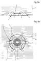
- Figures 5a and 5b are schematic views respectively in section and in plan of a third embodiment of the invention.
- the figures show that the disc 2 is equipped with a plurality of branches 4 made of the same material as the disc and arranged in its plane and its periphery to form a star 5.
- This third mode is completed by the same ring 3 present in the second execution mode.
- the field lines are represented in 6.
- the figure 5b shows that, captured by the branches 4 of the star 5, the field lines 6a tend to be radially (R direction according to the figure 2 )
- This third embodiment has the advantage of a disk 2 significantly reduced thanks to the presence of the branches 4 of the star 5. This leads to a lighter execution, less cumbersome and therefore more airy than that described previously.
- the standard disturbing effect of 4kA / m is reduced by a factor of 6 to 7 thanks to the proposed device.
- the simple disk 2 proposed in the first embodiment requires approximately twice as much material, which increases the mass of the device, therefore the moment of inertia and the energy consumed if this device equips a system. in movement, for example a tourbillon whose construction will be discussed at the end of this description.
- the device of the invention protects the hairspring of the timepiece regardless of the direction of the disturbing field entering said room, this thanks to the fact that the hairspring 1, the disk 2 or the star 5 which resulting and ring 3 are parts of revolution mounted coaxially on each other. We have seen that this is not the case of the device proposed in the document FR 1,408,872 cited above.
- the material with high magnetic permeance used to make the ring 3, the disk 2 or the star 5 is soft iron or, more specifically an iron-nickel alloy of the AFK502 type of the Arcelormittal firm. According to variants, it will typically be possible to use Fer-Nickel-Molybdenum, Iron-Nickel-Copper alloys.
- the figure 6 is a plan view of the third embodiment of the invention applied to a vortex and the figure 7 and a sectional view along the line VII-VII of the figure 6 .
- the tourbillon comprises a conventional set consisting of an escape wheel 10, an anchor 11 and a plate 12 connected to a balance 13 and a spiral 1. These elements are mounted in a rotating cage 14.
- the cage 14 operates as a second mobile and is usually one revolution per minute.
- the cage is secured to a second gear 15 driven by a medium wheel (not shown).
- a medium wheel not shown.
- Inside the cage 14 the role of the exhaust is conventional.
- the force is transmitted from an exhaust pinion 16 which meshes, in the manner of a satellite with a fixed second wheel 17 secured to the plate 18.
- figures 6 and 7 show that a star 5 and a ring 3, objects of the present invention, have been added to protect the hairspring against disturbing magnetic fields.
- the star here comprises six branches.
- this arrangement highlights the mechanism of the vortex which would not be the case if the star was replaced by a large diameter disk that would hide this mechanism.
Landscapes
- Physics & Mathematics (AREA)
- General Physics & Mathematics (AREA)
- Engineering & Computer Science (AREA)
- Metallurgy (AREA)
- Magnetic Treatment Devices (AREA)
- Springs (AREA)
Claims (5)
- Vorrichtung zum Schutz einer Zeitmessgerät-Spirale (1) gegen magnetische Störfelder, die von ausserhalb des Zeitmessgeräts stammen, welche Vorrichtung wenigstens eine Scheibe (2) mit hohem magnetischem Leitwert umfasst, die in einer Ebene angeordnet ist, die parallel zur Ebene der Spirale ist, wobei die Scheibe (2) und die Spirale (1) koaxial zueinander montiert sind und derart beschaffen sind, dass sie die magnetischen Störfelder, welche die Spirale erreichen, gemäss der radialen Richtung und/oder gemäss der Richtung der Höhe der Spirale ausrichten oder ablenken.
- Vorrichtung nach Anspruch 1, dadurch gekennzeichnet, dass die Scheibe von einem Ring (3) mit hohem magnetischem Leitwert überlagert ist, wobei dieser Ring um die Spirale (1) und koaxial zu dieser Letzteren angeordnet ist.
- Vorrichtung nach Anspruch 1, dadurch gekennzeichnet, dass die Scheibe (2) mit einer Vielzahl von Zweigen (4) ausgerüstet ist, die aus einem gleichen Material gefertigt sind, wie die Scheibe, und die in der Ebene und an der Peripherie dieser Letzteren angeordnet sind, um einen Stern (5) zu bilden.
- Vorrichtung nach Anspruch 3, dadurch gekennzeichnet, dass der Stern (5) von einem Ring (3) mit hohem magnetischem Leitwert überlagert ist, wobei dieser Ring um die Spirale (1) und koaxial zu dieser Letzteren angeordnet ist.
- Tourbillon, das eine Vorrichtung nach Anspruch 4 umfasst.
Priority Applications (6)
| Application Number | Priority Date | Filing Date | Title |
|---|---|---|---|
| EP09168003A EP2287683B1 (de) | 2009-08-17 | 2009-08-17 | Magnetic protection for hairspring in a timepiece |
| US12/857,075 US8337078B2 (en) | 2009-08-17 | 2010-08-16 | Magnetic protection for a timepiece balance spring |
| CN201010502900.8A CN101995814B (zh) | 2009-08-17 | 2010-08-17 | 时计游丝的磁保护装置 |
| KR1020100079379A KR20110018279A (ko) | 2009-08-17 | 2010-08-17 | 시계의 밸런스 스프링용 자기 보호장치 |
| JP2010182193A JP5391163B2 (ja) | 2009-08-17 | 2010-08-17 | 時計用テンプ輪スプリングの保護装置 |
| HK11109885.6A HK1155822B (en) | 2009-08-17 | 2011-09-20 | Magnetic protection for a timepiece balance spring |
Applications Claiming Priority (1)
| Application Number | Priority Date | Filing Date | Title |
|---|---|---|---|
| EP09168003A EP2287683B1 (de) | 2009-08-17 | 2009-08-17 | Magnetic protection for hairspring in a timepiece |
Publications (2)
| Publication Number | Publication Date |
|---|---|
| EP2287683A1 EP2287683A1 (de) | 2011-02-23 |
| EP2287683B1 true EP2287683B1 (de) | 2012-10-31 |
Family
ID=41514244
Family Applications (1)
| Application Number | Title | Priority Date | Filing Date |
|---|---|---|---|
| EP09168003A Active EP2287683B1 (de) | 2009-08-17 | 2009-08-17 | Magnetic protection for hairspring in a timepiece |
Country Status (5)
| Country | Link |
|---|---|
| US (1) | US8337078B2 (de) |
| EP (1) | EP2287683B1 (de) |
| JP (1) | JP5391163B2 (de) |
| KR (1) | KR20110018279A (de) |
| CN (1) | CN101995814B (de) |
Families Citing this family (3)
| Publication number | Priority date | Publication date | Assignee | Title |
|---|---|---|---|---|
| EP2466396A1 (de) * | 2010-12-15 | 2012-06-20 | The Swatch Group Research and Development Ltd. | Magnetische Abschirmung für Spiralunruh einer Uhr |
| EP2607969B1 (de) | 2011-12-19 | 2014-09-17 | Nivarox-FAR S.A. | Uhrwerk mit geringer magnetischer Empfindlichkeit |
| CH707503A2 (fr) * | 2013-01-17 | 2014-07-31 | Omega Sa | Axe de pivotement pour mouvement horloger. |
Family Cites Families (14)
| Publication number | Priority date | Publication date | Assignee | Title |
|---|---|---|---|---|
| CH122391A (fr) | 1926-10-22 | 1927-09-16 | Ditisheim Paul | Montre. |
| US2350838A (en) * | 1942-02-04 | 1944-06-06 | Straumann Reinhard | Compensating device for watch balances |
| US2724235A (en) * | 1951-10-11 | 1955-11-22 | Junghans Geb Ag | Magnetic clock movement |
| US3002138A (en) * | 1958-06-24 | 1961-09-26 | Gen Time Corp | Electrically powered oscillatory balance |
| CH348367A (de) * | 1958-07-18 | 1960-08-15 | Junghans Geb Ag | Antimagnetische Uhr |
| FR1405215A (fr) * | 1962-07-10 | 1965-07-09 | Lip Sa | Montre électrique perfectionnée |
| US3335561A (en) * | 1964-05-18 | 1967-08-15 | Seiko Instr & Electronics | Contactless battery timepiece |
| FR1408872A (fr) | 1964-07-08 | 1965-08-20 | Lip Sa | Dispositif de protection des montres contre les champs magnétiques |
| JPS546223B2 (de) * | 1973-10-16 | 1979-03-26 | ||
| US3943701A (en) * | 1975-01-08 | 1976-03-16 | Timex Corporation | Regulator and balance bridge arrangement for a horological device |
| JPS56103886U (de) * | 1980-01-11 | 1981-08-14 | ||
| JPS58129190U (ja) * | 1983-01-20 | 1983-09-01 | セイコーエプソン株式会社 | 電子時計の耐磁板 |
| DE19651320B4 (de) * | 1996-12-11 | 2004-06-03 | Schmidt, Lothar | Schwingsystem |
| DE602005023633D1 (de) * | 2004-10-26 | 2010-10-28 | Tag Heuer Sa | Armbanduhr-regulierungsglied und mechanisches uhrwerk mit einem solchen regulierungsglied |
-
2009
- 2009-08-17 EP EP09168003A patent/EP2287683B1/de active Active
-
2010
- 2010-08-16 US US12/857,075 patent/US8337078B2/en active Active
- 2010-08-17 JP JP2010182193A patent/JP5391163B2/ja active Active
- 2010-08-17 KR KR1020100079379A patent/KR20110018279A/ko not_active Ceased
- 2010-08-17 CN CN201010502900.8A patent/CN101995814B/zh active Active
Also Published As
| Publication number | Publication date |
|---|---|
| JP5391163B2 (ja) | 2014-01-15 |
| CN101995814A (zh) | 2011-03-30 |
| HK1155822A1 (en) | 2012-05-25 |
| US20110038234A1 (en) | 2011-02-17 |
| US8337078B2 (en) | 2012-12-25 |
| JP2011039061A (ja) | 2011-02-24 |
| KR20110018279A (ko) | 2011-02-23 |
| EP2287683A1 (de) | 2011-02-23 |
| CN101995814B (zh) | 2015-02-18 |
Similar Documents
| Publication | Publication Date | Title |
|---|---|---|
| EP2018601B1 (de) | Spiralfeder-spiralrollegesamtheit für ein uhrwerk | |
| EP2102717B1 (de) | Mechanischer oszillator für uhr | |
| EP2496990B1 (de) | Einstellungselement für eine armbanduhr sowie uhr mit einem solchen einstellungselement | |
| EP2463732A1 (de) | Schlagwerkmechanismus einer Armbanduhr oder einer Spieluhr | |
| EP3106933B1 (de) | Magnetischer schwenkeinrichtung einer welle in einem uhrwerk | |
| EP2690506B1 (de) | Antischwingungsspirale für Uhr | |
| WO2014016094A1 (fr) | Balancier-spiral d'horlogerie | |
| EP2206022B1 (de) | Stossdämpfende lagerung für eine uhr | |
| EP2287683A1 (de) | Magnetic protection for hairspring in a timepiece | |
| EP1513029B1 (de) | Spiralrolle für Uhrwerk | |
| EP2652560B1 (de) | Magnetische abschirmung für die spiralfeder einer uhr | |
| EP3185083B1 (de) | Mechanischer uhrmechanismus mit einer ankerhemmung | |
| EP2753985B1 (de) | Uhrwerk mit unruh und spiralfeder | |
| EP3908887A1 (de) | Regulierungsmechanismus für ein uhrwerk | |
| EP3109712A1 (de) | Magnetische vorrichtung zum schwenken einer welle in einem uhrwerk | |
| CH701672A2 (fr) | Protection magnétique d'un spiral de pièce d'horlogerie. | |
| EP2607969B1 (de) | Uhrwerk mit geringer magnetischer Empfindlichkeit | |
| CH704211A2 (fr) | Blindage magnétique pour spiral de pièce d'horlogerie. | |
| CH705584B1 (fr) | Palier amortisseur pour balancier-spiral, balancier-spiral le comportant, et pièce d'horlogerie. | |
| EP2987035B1 (de) | Mechanischer oszillator für ein uhrwerk | |
| CH705906B1 (fr) | Système amortisseur de chocs pour un axe d'un mobile d'une pièce d'horlogerie. | |
| EP2497095A1 (de) | Einstellungselement für eine armbanduhr sowie uhr mit einem solchen einstellungselement | |
| CH720975B1 (fr) | Balancier à inertie variable | |
| CH700606A1 (fr) | Marteau de sonnerie pour mouvement horloger. | |
| CH698753B1 (fr) | Masse de remontage oscillante et pièce d'horlogerie munie d'une telle masse de remontage. |
Legal Events
| Date | Code | Title | Description |
|---|---|---|---|
| PUAI | Public reference made under article 153(3) epc to a published international application that has entered the european phase |
Free format text: ORIGINAL CODE: 0009012 |
|
| AK | Designated contracting states |
Kind code of ref document: A1 Designated state(s): AT BE BG CH CY CZ DE DK EE ES FI FR GB GR HR HU IE IS IT LI LT LU LV MC MK MT NL NO PL PT RO SE SI SK SM TR |
|
| 17P | Request for examination filed |
Effective date: 20110823 |
|
| 17Q | First examination report despatched |
Effective date: 20110919 |
|
| GRAP | Despatch of communication of intention to grant a patent |
Free format text: ORIGINAL CODE: EPIDOSNIGR1 |
|
| GRAS | Grant fee paid |
Free format text: ORIGINAL CODE: EPIDOSNIGR3 |
|
| GRAA | (expected) grant |
Free format text: ORIGINAL CODE: 0009210 |
|
| AK | Designated contracting states |
Kind code of ref document: B1 Designated state(s): AT BE BG CH CY CZ DE DK EE ES FI FR GB GR HR HU IE IS IT LI LT LU LV MC MK MT NL NO PL PT RO SE SI SK SM TR |
|
| REG | Reference to a national code |
Ref country code: GB Ref legal event code: FG4D Free format text: NOT ENGLISH Ref country code: CH Ref legal event code: EP |
|
| REG | Reference to a national code |
Ref country code: AT Ref legal event code: REF Ref document number: 582324 Country of ref document: AT Kind code of ref document: T Effective date: 20121115 |
|
| REG | Reference to a national code |
Ref country code: IE Ref legal event code: FG4D Free format text: LANGUAGE OF EP DOCUMENT: FRENCH |
|
| REG | Reference to a national code |
Ref country code: CH Ref legal event code: NV Representative=s name: ICB INGENIEURS CONSEILS EN BREVETS SA, CH |
|
| REG | Reference to a national code |
Ref country code: DE Ref legal event code: R096 Ref document number: 602009010772 Country of ref document: DE Effective date: 20121227 |
|
| REG | Reference to a national code |
Ref country code: AT Ref legal event code: MK05 Ref document number: 582324 Country of ref document: AT Kind code of ref document: T Effective date: 20121031 |
|
| REG | Reference to a national code |
Ref country code: LT Ref legal event code: MG4D |
|
| REG | Reference to a national code |
Ref country code: NL Ref legal event code: VDEP Effective date: 20121031 |
|
| PG25 | Lapsed in a contracting state [announced via postgrant information from national office to epo] |
Ref country code: SE Free format text: LAPSE BECAUSE OF FAILURE TO SUBMIT A TRANSLATION OF THE DESCRIPTION OR TO PAY THE FEE WITHIN THE PRESCRIBED TIME-LIMIT Effective date: 20121031 Ref country code: NO Free format text: LAPSE BECAUSE OF FAILURE TO SUBMIT A TRANSLATION OF THE DESCRIPTION OR TO PAY THE FEE WITHIN THE PRESCRIBED TIME-LIMIT Effective date: 20130131 Ref country code: FI Free format text: LAPSE BECAUSE OF FAILURE TO SUBMIT A TRANSLATION OF THE DESCRIPTION OR TO PAY THE FEE WITHIN THE PRESCRIBED TIME-LIMIT Effective date: 20121031 Ref country code: ES Free format text: LAPSE BECAUSE OF FAILURE TO SUBMIT A TRANSLATION OF THE DESCRIPTION OR TO PAY THE FEE WITHIN THE PRESCRIBED TIME-LIMIT Effective date: 20130211 Ref country code: HR Free format text: LAPSE BECAUSE OF FAILURE TO SUBMIT A TRANSLATION OF THE DESCRIPTION OR TO PAY THE FEE WITHIN THE PRESCRIBED TIME-LIMIT Effective date: 20121031 Ref country code: IS Free format text: LAPSE BECAUSE OF FAILURE TO SUBMIT A TRANSLATION OF THE DESCRIPTION OR TO PAY THE FEE WITHIN THE PRESCRIBED TIME-LIMIT Effective date: 20130228 Ref country code: NL Free format text: LAPSE BECAUSE OF FAILURE TO SUBMIT A TRANSLATION OF THE DESCRIPTION OR TO PAY THE FEE WITHIN THE PRESCRIBED TIME-LIMIT Effective date: 20121031 Ref country code: LT Free format text: LAPSE BECAUSE OF FAILURE TO SUBMIT A TRANSLATION OF THE DESCRIPTION OR TO PAY THE FEE WITHIN THE PRESCRIBED TIME-LIMIT Effective date: 20121031 |
|
| PG25 | Lapsed in a contracting state [announced via postgrant information from national office to epo] |
Ref country code: GR Free format text: LAPSE BECAUSE OF FAILURE TO SUBMIT A TRANSLATION OF THE DESCRIPTION OR TO PAY THE FEE WITHIN THE PRESCRIBED TIME-LIMIT Effective date: 20130201 Ref country code: PL Free format text: LAPSE BECAUSE OF FAILURE TO SUBMIT A TRANSLATION OF THE DESCRIPTION OR TO PAY THE FEE WITHIN THE PRESCRIBED TIME-LIMIT Effective date: 20121031 Ref country code: SI Free format text: LAPSE BECAUSE OF FAILURE TO SUBMIT A TRANSLATION OF THE DESCRIPTION OR TO PAY THE FEE WITHIN THE PRESCRIBED TIME-LIMIT Effective date: 20121031 Ref country code: PT Free format text: LAPSE BECAUSE OF FAILURE TO SUBMIT A TRANSLATION OF THE DESCRIPTION OR TO PAY THE FEE WITHIN THE PRESCRIBED TIME-LIMIT Effective date: 20130228 Ref country code: LV Free format text: LAPSE BECAUSE OF FAILURE TO SUBMIT A TRANSLATION OF THE DESCRIPTION OR TO PAY THE FEE WITHIN THE PRESCRIBED TIME-LIMIT Effective date: 20121031 |
|
| PG25 | Lapsed in a contracting state [announced via postgrant information from national office to epo] |
Ref country code: AT Free format text: LAPSE BECAUSE OF FAILURE TO SUBMIT A TRANSLATION OF THE DESCRIPTION OR TO PAY THE FEE WITHIN THE PRESCRIBED TIME-LIMIT Effective date: 20121031 |
|
| PG25 | Lapsed in a contracting state [announced via postgrant information from national office to epo] |
Ref country code: BG Free format text: LAPSE BECAUSE OF FAILURE TO SUBMIT A TRANSLATION OF THE DESCRIPTION OR TO PAY THE FEE WITHIN THE PRESCRIBED TIME-LIMIT Effective date: 20130131 Ref country code: EE Free format text: LAPSE BECAUSE OF FAILURE TO SUBMIT A TRANSLATION OF THE DESCRIPTION OR TO PAY THE FEE WITHIN THE PRESCRIBED TIME-LIMIT Effective date: 20121031 Ref country code: CZ Free format text: LAPSE BECAUSE OF FAILURE TO SUBMIT A TRANSLATION OF THE DESCRIPTION OR TO PAY THE FEE WITHIN THE PRESCRIBED TIME-LIMIT Effective date: 20121031 Ref country code: DK Free format text: LAPSE BECAUSE OF FAILURE TO SUBMIT A TRANSLATION OF THE DESCRIPTION OR TO PAY THE FEE WITHIN THE PRESCRIBED TIME-LIMIT Effective date: 20121031 Ref country code: SK Free format text: LAPSE BECAUSE OF FAILURE TO SUBMIT A TRANSLATION OF THE DESCRIPTION OR TO PAY THE FEE WITHIN THE PRESCRIBED TIME-LIMIT Effective date: 20121031 |
|
| PG25 | Lapsed in a contracting state [announced via postgrant information from national office to epo] |
Ref country code: IT Free format text: LAPSE BECAUSE OF FAILURE TO SUBMIT A TRANSLATION OF THE DESCRIPTION OR TO PAY THE FEE WITHIN THE PRESCRIBED TIME-LIMIT Effective date: 20121031 Ref country code: RO Free format text: LAPSE BECAUSE OF FAILURE TO SUBMIT A TRANSLATION OF THE DESCRIPTION OR TO PAY THE FEE WITHIN THE PRESCRIBED TIME-LIMIT Effective date: 20121031 |
|
| PLBE | No opposition filed within time limit |
Free format text: ORIGINAL CODE: 0009261 |
|
| STAA | Information on the status of an ep patent application or granted ep patent |
Free format text: STATUS: NO OPPOSITION FILED WITHIN TIME LIMIT |
|
| 26N | No opposition filed |
Effective date: 20130801 |
|
| REG | Reference to a national code |
Ref country code: DE Ref legal event code: R097 Ref document number: 602009010772 Country of ref document: DE Effective date: 20130801 |
|
| PG25 | Lapsed in a contracting state [announced via postgrant information from national office to epo] |
Ref country code: CY Free format text: LAPSE BECAUSE OF FAILURE TO SUBMIT A TRANSLATION OF THE DESCRIPTION OR TO PAY THE FEE WITHIN THE PRESCRIBED TIME-LIMIT Effective date: 20121031 |
|
| BERE | Be: lapsed |
Owner name: THE SWATCH GROUP RESEARCH AND DEVELOPMENT LTD. Effective date: 20130831 |
|
| PG25 | Lapsed in a contracting state [announced via postgrant information from national office to epo] |
Ref country code: MC Free format text: LAPSE BECAUSE OF FAILURE TO SUBMIT A TRANSLATION OF THE DESCRIPTION OR TO PAY THE FEE WITHIN THE PRESCRIBED TIME-LIMIT Effective date: 20121031 |
|
| REG | Reference to a national code |
Ref country code: IE Ref legal event code: MM4A |
|
| PG25 | Lapsed in a contracting state [announced via postgrant information from national office to epo] |
Ref country code: BE Free format text: LAPSE BECAUSE OF NON-PAYMENT OF DUE FEES Effective date: 20130831 |
|
| PG25 | Lapsed in a contracting state [announced via postgrant information from national office to epo] |
Ref country code: IE Free format text: LAPSE BECAUSE OF NON-PAYMENT OF DUE FEES Effective date: 20130817 |
|
| PG25 | Lapsed in a contracting state [announced via postgrant information from national office to epo] |
Ref country code: SM Free format text: LAPSE BECAUSE OF FAILURE TO SUBMIT A TRANSLATION OF THE DESCRIPTION OR TO PAY THE FEE WITHIN THE PRESCRIBED TIME-LIMIT Effective date: 20121031 |
|
| PG25 | Lapsed in a contracting state [announced via postgrant information from national office to epo] |
Ref country code: TR Free format text: LAPSE BECAUSE OF FAILURE TO SUBMIT A TRANSLATION OF THE DESCRIPTION OR TO PAY THE FEE WITHIN THE PRESCRIBED TIME-LIMIT Effective date: 20121031 Ref country code: MT Free format text: LAPSE BECAUSE OF FAILURE TO SUBMIT A TRANSLATION OF THE DESCRIPTION OR TO PAY THE FEE WITHIN THE PRESCRIBED TIME-LIMIT Effective date: 20121031 |
|
| PG25 | Lapsed in a contracting state [announced via postgrant information from national office to epo] |
Ref country code: HU Free format text: LAPSE BECAUSE OF FAILURE TO SUBMIT A TRANSLATION OF THE DESCRIPTION OR TO PAY THE FEE WITHIN THE PRESCRIBED TIME-LIMIT; INVALID AB INITIO Effective date: 20090817 Ref country code: MK Free format text: LAPSE BECAUSE OF FAILURE TO SUBMIT A TRANSLATION OF THE DESCRIPTION OR TO PAY THE FEE WITHIN THE PRESCRIBED TIME-LIMIT Effective date: 20121031 Ref country code: LU Free format text: LAPSE BECAUSE OF NON-PAYMENT OF DUE FEES Effective date: 20130817 |
|
| REG | Reference to a national code |
Ref country code: FR Ref legal event code: PLFP Year of fee payment: 8 |
|
| REG | Reference to a national code |
Ref country code: FR Ref legal event code: PLFP Year of fee payment: 9 |
|
| REG | Reference to a national code |
Ref country code: FR Ref legal event code: PLFP Year of fee payment: 10 |
|
| P01 | Opt-out of the competence of the unified patent court (upc) registered |
Effective date: 20230615 |
|
| PGFP | Annual fee paid to national office [announced via postgrant information from national office to epo] |
Ref country code: GB Payment date: 20230720 Year of fee payment: 15 |
|
| GBPC | Gb: european patent ceased through non-payment of renewal fee |
Effective date: 20240817 |
|
| PG25 | Lapsed in a contracting state [announced via postgrant information from national office to epo] |
Ref country code: GB Free format text: LAPSE BECAUSE OF NON-PAYMENT OF DUE FEES Effective date: 20240817 |
|
| PGFP | Annual fee paid to national office [announced via postgrant information from national office to epo] |
Ref country code: DE Payment date: 20250724 Year of fee payment: 17 |
|
| PGFP | Annual fee paid to national office [announced via postgrant information from national office to epo] |
Ref country code: FR Payment date: 20250725 Year of fee payment: 17 |
|
| PGFP | Annual fee paid to national office [announced via postgrant information from national office to epo] |
Ref country code: CH Payment date: 20250901 Year of fee payment: 17 |